Close
0%
0%

Pilot-1 CPU (ECM-16/TTL partial build)

This is a proof-of-concept sub-project spun off from my main homebrew CPU project.

Similar projects worth following
This project is a partial build of my ECM-16/TTL computer, and is very limited, though arguably a Turing-complete machine.
It is a sort of Harward architecture, as instructions are held apart from data on which they operate, and the instructions are immutable (they are stored in ROM).
This machine operates on 16-bit words of data, and has 16-bit wide instructions.
The Pilot-1 consists of mainly the Calculating Core (eight 16-bit registers coupled with richly featured 16-bit ALU), the instruction ROM (sixteen 16-bit words that could be set using switch banks) and the Provisional Control Unit, that has clock generation circuitry, as well as partial instruction decoder and flip-flops holding two of ALU status flags.

This is a part of my main project to build a homebrew computer.

I decided to make it its own project as it is already built and is a programmable computer in its own right, just very limited. Also to have info about it in one place and not buried among other posts on main project.

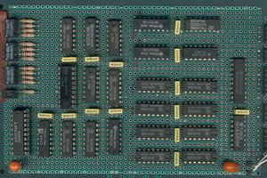
The overall schematic:

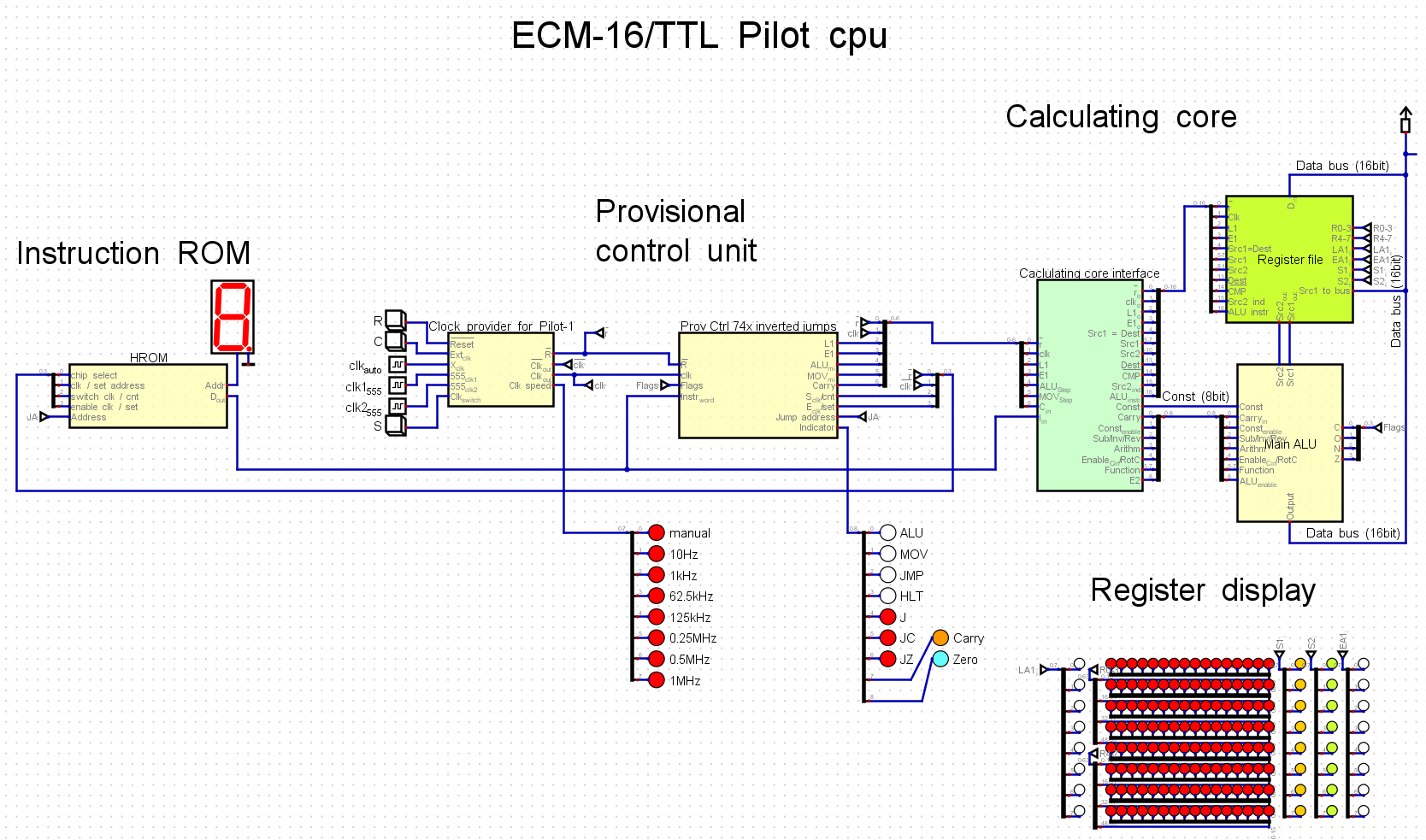
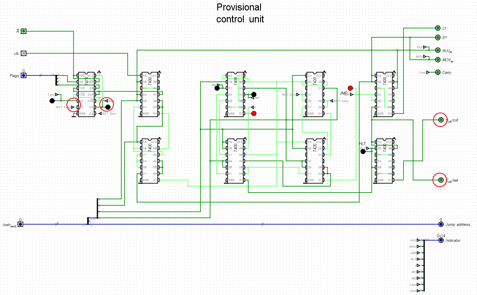
The only part that is specific and dedicated to the Pilot-1 machine is the Provisional Control Unit.

The instruction ROM is a programmable-by-hand switch bank/diode ROM board I built a while ago.

And the Calculating Core, consisting of ALU and Register File, alongside its Register Display is intended to become an integral part of ECM-16/TTL homebrew computer that is now work in progress.

The machine is very limited in how much data it can operate on and how many instructions (max 16) could fit into instruction ROM.

There is no proper RAM, so the only places where data could be held and operated upon are the eight General Purpose Registers.

There is also a lack of I/O capabilities: aside from Reset button and clock adjustments, there are no way to influence the operation at runtime (no inputs). Only way to change behaviour is to reprogram the ROM by hand. As for the output, one can see the contents of registers via the Register Display, and that is all.

Aside from the rich set of ALU instructions, this machine also features an instruction to move data between registers, the unconditional jump, two conditional jumps (on Not Carry and on Not Zero), and Halt instruction, which is kind of jump, but always to its own address.

With these conditional jumps there are many possibilities which can be realized with max of just 16 instructions in a program.

  • Pilot-1 is fully functional!

    Pavel01/23/2022 at 20:06 0 comments

    Previously I had some issues with the working of the setup, and then I was quick to blame the HROM and the Provisional Control boards for what I saw as stuck bits and intermittent resets. As I finally got to debugging, I found out that indeed there were a couple of problems in HROM. But that was not all, and to my surprise, a couple of bugs were found to be residing in the Calculating Core circuitry instead of Provisional control board.

    The problems were:

    - bit 6 was shared between r0 and r1 -- this was caused by malfunction (short) of one of the 74hc151 ICs in Src2 selector board of Register File; swapping in new IC solved the problem.

    - bit 9 was added intermittently when performing ADD operation -- this problem was a bit tricky, as it was fairly rare event that was apparent on high clock speeds. Eventually I traced it to improper solder joint on under one of the 74hc86 chips of Negator circuit on Misc board inside the ALU. The joint looked ok from afar, but closer look revealed that two wires were just touching each other, and this contact was very bad; after soldering on that joint was properly done, the bug was gone. 

    Since then no other bugs shown themselves, and the machine is apparently stable at 1 MHz clock, for several hours in row at least.

    Following is the test program, which sets bit0 of r0 to 1, then moves t across all bits of registers r0-r6, and finally adds it to sum in register r7 (JNC and JNZ are equivalent in this case, as when the single bit rolls off, it is saved to carry, and register itself is zero, using both here just to test both work correctly):

    0:    ADD r0 0x01    ;set bit 0 of register 0 to 1
    1:    ROLC r0 r0     ;rotate r0 left through carry, saving result to r0 
    2:    JNC 0x1        ;if no carry, jump to address 0x1
    3:    RORC r1 r1     ;rotate r1 right through carry, saving result to r1
    4:    JNZ 0x3        ;if not zero, jump to address 0x3
    5:    ROLC r2 r2
    6:    JNC 0x5
    7:    RORC r3 r3
    8:    JNZ 0x7
    9:    ROLC r4 r4
    A:    JNC 0x9
    B:    RORC r5 r5
    C:    JNZ 0xA
    D:    ROLC r6 r6
    E:    JNC 0xD
    F:    ADD r7 0x01    ;when full journey is complete, add 1 to r7

    And here is video of this program executing at different speeds:

  • Small wiring change to the control board

    Pavel01/06/2022 at 16:32 0 comments

    I found out that the choice to use positive conditions for conditional jumps forces me to use additional instructions for creating a loop. As the simplest example, here is a program which shifts a single bit to the left and stops when it falls off:

    0     ADD r0 0x01    ; initialising register r0 with value of 1
    1     ROLC r0 r0     ; rotating word in register r0 through carry 1 bit left
    2     JC [4]         ; jump to address 4 if carry is set
    3     J [1]          ; jump to address 1 to continue rotation
    4     HLT            ; stop execution

     As seen on snippet above, there are two jump instructions in row, and the conditional jump is executed each time, but until the end is just skipped, as condition is false.

    Given that here I can only use 16 words for instruction, this is just dead weight that bloats the code. It would be wiser to use negative condition, Jump If Not Carry, thus needing only 1 jump instruction: 

    0     ADD r0 0x01    ; initialising register r0 with value of 1
    1     ROLC r0 r0     ; rotating word in register r0 through carry 1 bit left
    2     JNC [1]        ; if carry is not set, jump to address 1 to continue rotation
    3     HLT            ; else, stop execution

    To change the positive to negative condition, a simple rewiring is sufficient: as the flag value is stored in 74hc74 d-flip-flop, I just need to use its inverted outputs instead of direct ones, and switch places for couple of outputs:


    As for the whole Pilot-1 contraption, it has at least 1 bug (most probably intermittent short in Fast Adder) which I still haven't fixed yet. This bug shows as stuck bit 9, and is prominent at faster clock speeds, so it is fairly difficult to pinpoint the root cause.

  • First turning on at completion

    Pavel01/06/2022 at 11:03 0 comments

    The details are in this blog entry.

View all 3 project logs

Enjoy this project?

Share

Discussions

Similar Projects

Does this project spark your interest?

Become a member to follow this project and never miss any updates