 Alex Bowen
The computer itself was designed similarly to a modern PC, at least in principal. It has a motherboard with slots for the CPU, RAM, and ROM, the system clock (the good ol' 555 running at 400 Hz), and slots to plug in peripherals. At the time it was submitted for my class, it had one peripheral card, which was an IO controller that interfaced the CPU to the switches and LEDs on the front of the plexiglass case.
The RAM was a 32k SRAM from Cypress, and the ROM was an 8k EEPROM from Samsung. I enabled one or the other with a "North Bridge" that was just a 74139 2-to-4 line decoder that was monitoring the Z80's A15 IORQ lines, to see whether it was looking at the upper or lower half of its address space, and if it was trying to do IO or access system memory.
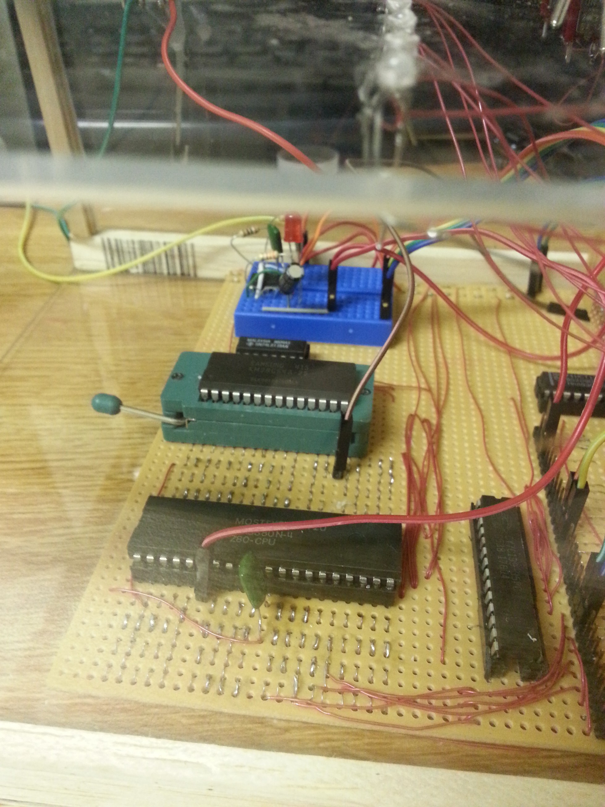
For the IO peripherals, I organized a selection of the CPU lines, along with power and ground, into a 30-column strip of wire on the motherboard where I could solder in rows of male or female pin headers to make peripheral slots. Four of these lines were the lowest four bits of the address bus, and I routed address lines 4 and 5, along with the IORQ line to a 74138 3-to-8 line decoder. This setup would allow me to select between 8 peripheral slots, each capable of supporting 16 ports. The submitted project only ended up with two slots, one row of male headers for debugging and last-minute wiring, and one female slot for the lonely IO card.
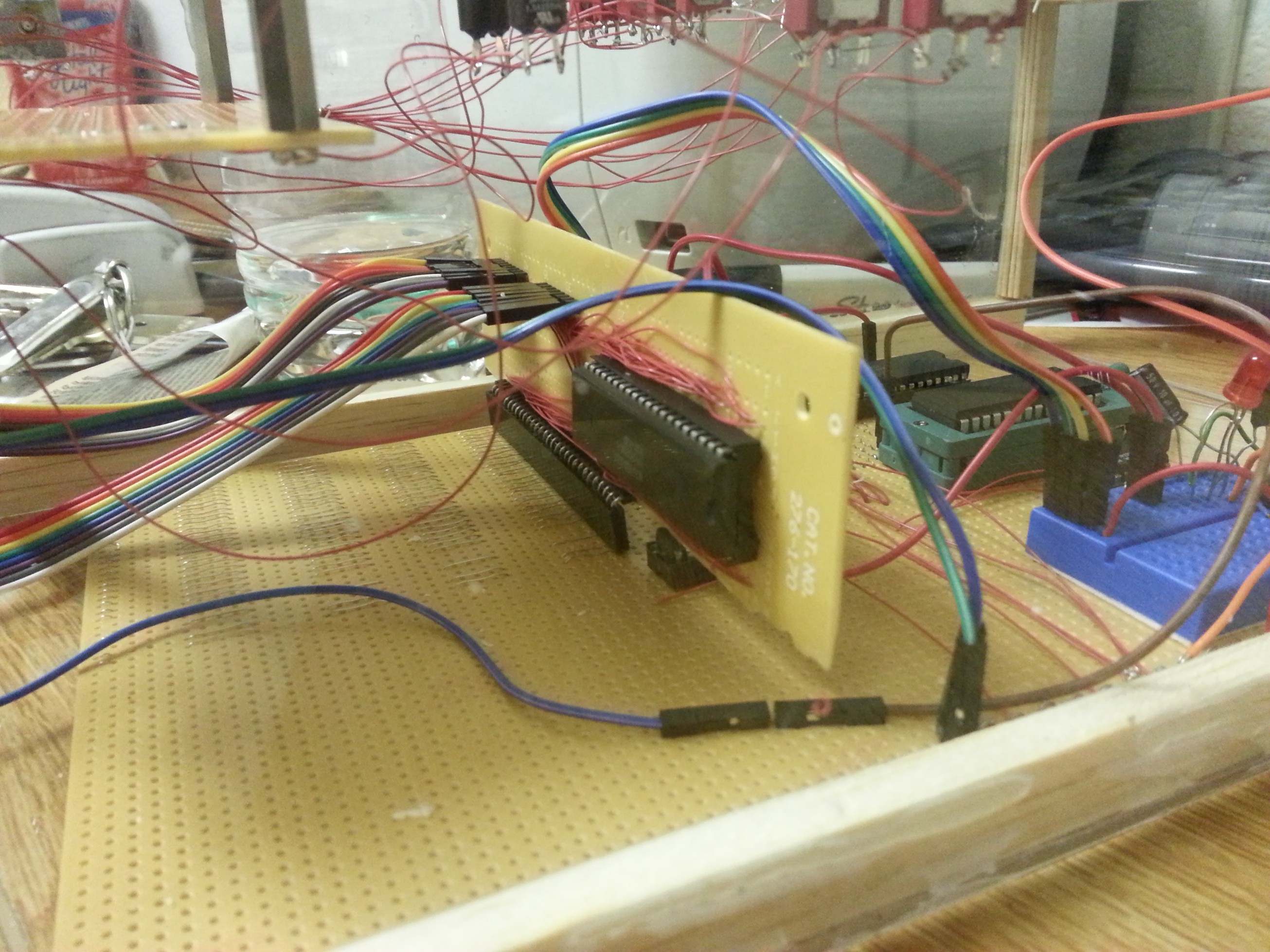
The IO card was basically just a host for the Z80-PIO chip. It's a special chip designed specifically for the Z80 that provides two 8-bit ports which can be programmed for input, output, or bidirectional data. It also provides a few useful functions for providing interrupts, though these weren't used here. The card itself basically just interfaces the PIO chip to the motherboard and case, with its "A" port connected to the toggle switches and push-buttons, and its "B" port connected to the LEDs.
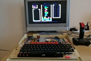
While I had hoped to have something much more advanced, the final submission was essentially just a calculator. The user flipped out a 6-bit number with the row of toggle switches, selected between addition or subtraction with one of the bit toggle switches, pressed a push-button to enter the first number, flipped out a different 6-bit number, and pressed the button again to see the answer.
The Z80 assembly program behind all of that is stored on the 8K EEPROM. The program was written in a compiler called "Z80 ASM," and then the binaries were put on a Raspberry Pi hooked up to a custom-built programmer for my specific EEPROM.
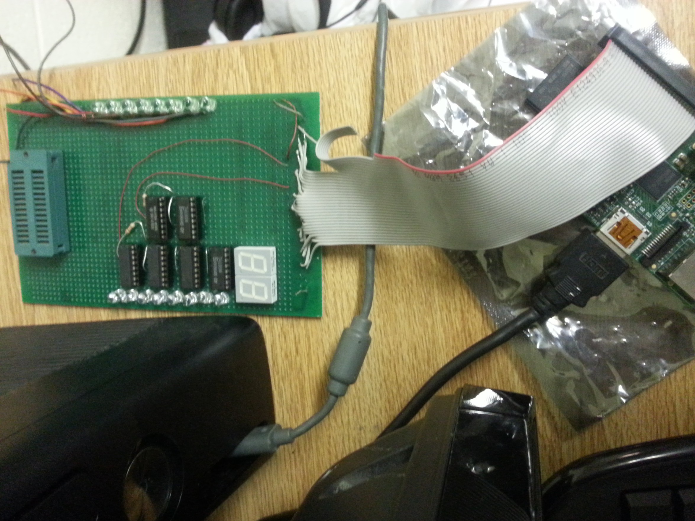
The programmer was pretty simple. It used four daisy-chained 74193 counter ICs to point to the address it was writing to, and two more counters to set the byte. Luckily, I did not submit the programmer as part of the school project, so it is safely in my posession for when I build the next one.


 6502Nerd
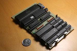
 Hayden Kroepfl
 matseng
 Voja Antonic