The multiplexer block will route 1 of the 4, 4-bit buses to the drive circuit (the BCD to 7SEG decoder). Its implementation is relatively common and covered in most introductory electronics courses. One difference being I used the basic 1x 555 AND block so there’s a couple extra inverters included.
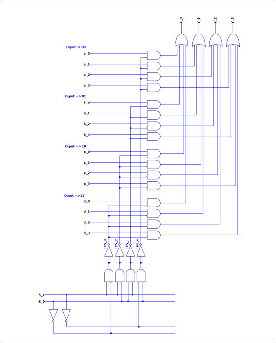
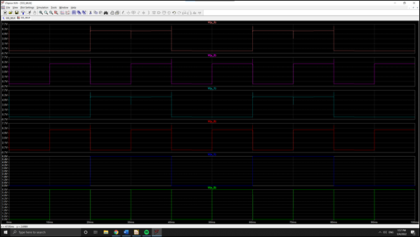
The final 4-1 line MUX requires a total of 26x 555’s, 16 diodes, and a handful of resistors. Its simulation results are shown below. Note that for this simulation channel 0 contains 0000, 1 contains 0101, 2 contains 1010, and 3 contains 1111.
Discussions
Become a Hackaday.io Member
Create an account to leave a comment. Already have an account? Log In.