First off I want to interface my laptop via serial to the Roomba. Send some commands, get some response.
Some places I found info and inspiration:
https://github.com/johnboiles/esp-roomba-mqtt
https://github.com/incmve/Roomba-esp8266-MQTT
https://www.hackster.io/mjrobot/controlling-a-roomba-robot-with-arduino-and-android-device-56970d
As always, ifixit has info on how to remove covers and the battery without destroying anything.
https://www.ifixit.com/Device/iRobot_Roomba_630
And a lot of documentation can be found on the iRobot site.
https://edu.irobot.com/what-we-offer/create-robot
Including the "iRobot® Create® 2 Open Interface (OI) Specification based on the iRobot® Roomba® 600"
That sounds like exactly what I need! And it includes the pinout and baudrate. So lets start there.
Pin Name Description
1 Vpwr Roomba battery + (unregulated)
2 Vpwr Roomba battery + (unregulated)
3 RXD 0 – 5V Serial input to Roomba
4 TXD 0 – 5V Serial output from Roomba
5 BRC Baud Rate Change
6 GND Roomba battery ground
7 GND Roomba battery ground
Probing around with the scope reveals data on the TXD when turning the Roomba "on" or "off" (pushing the clean button)
I have a USB-Serial cable I also use for programming. It uses 3.3V logic levels though so I need some sort of level conversion. The ESP8266 I want to use also uses 3.3V, so this is a thing I have to tackle anyway.
On the iRobot site they even recommend a voltage level shifting circuit using a FET. Other options I found just use a voltage divider using two resistors.
I tried both circuits to check rise times / edges. The voltage divider seems to do adequately.
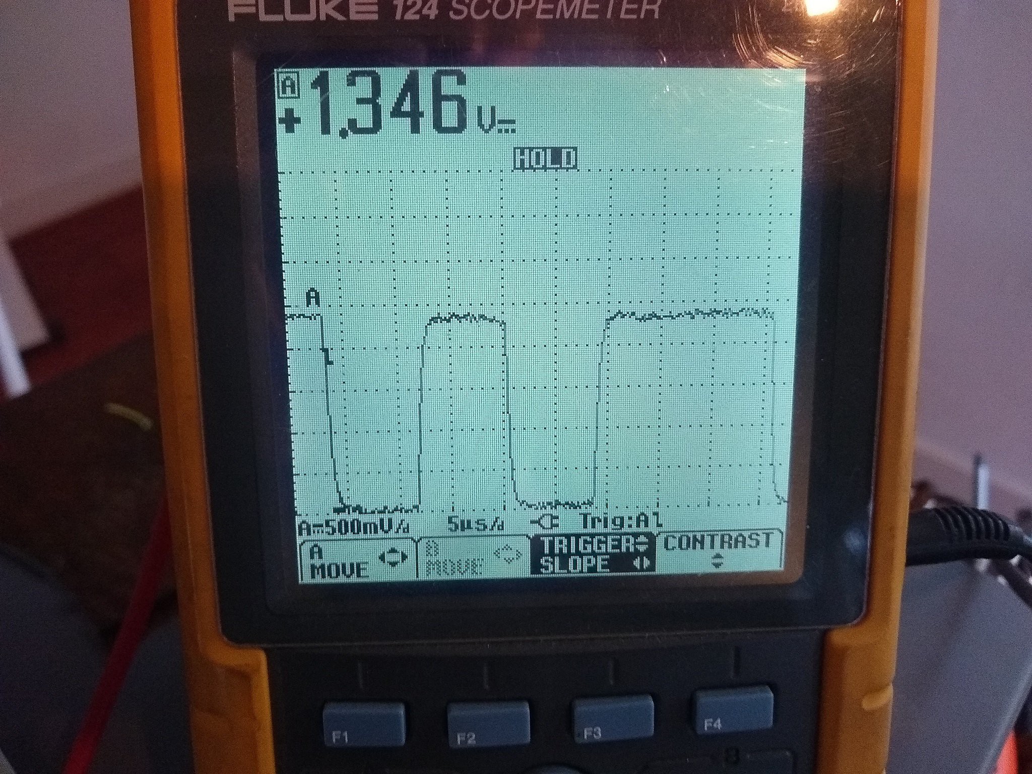
With the FET I would also need a regulated 5V source which I don't plan to have when everything is built in.
A voltage devider will do. I'm using 2K and 1K.
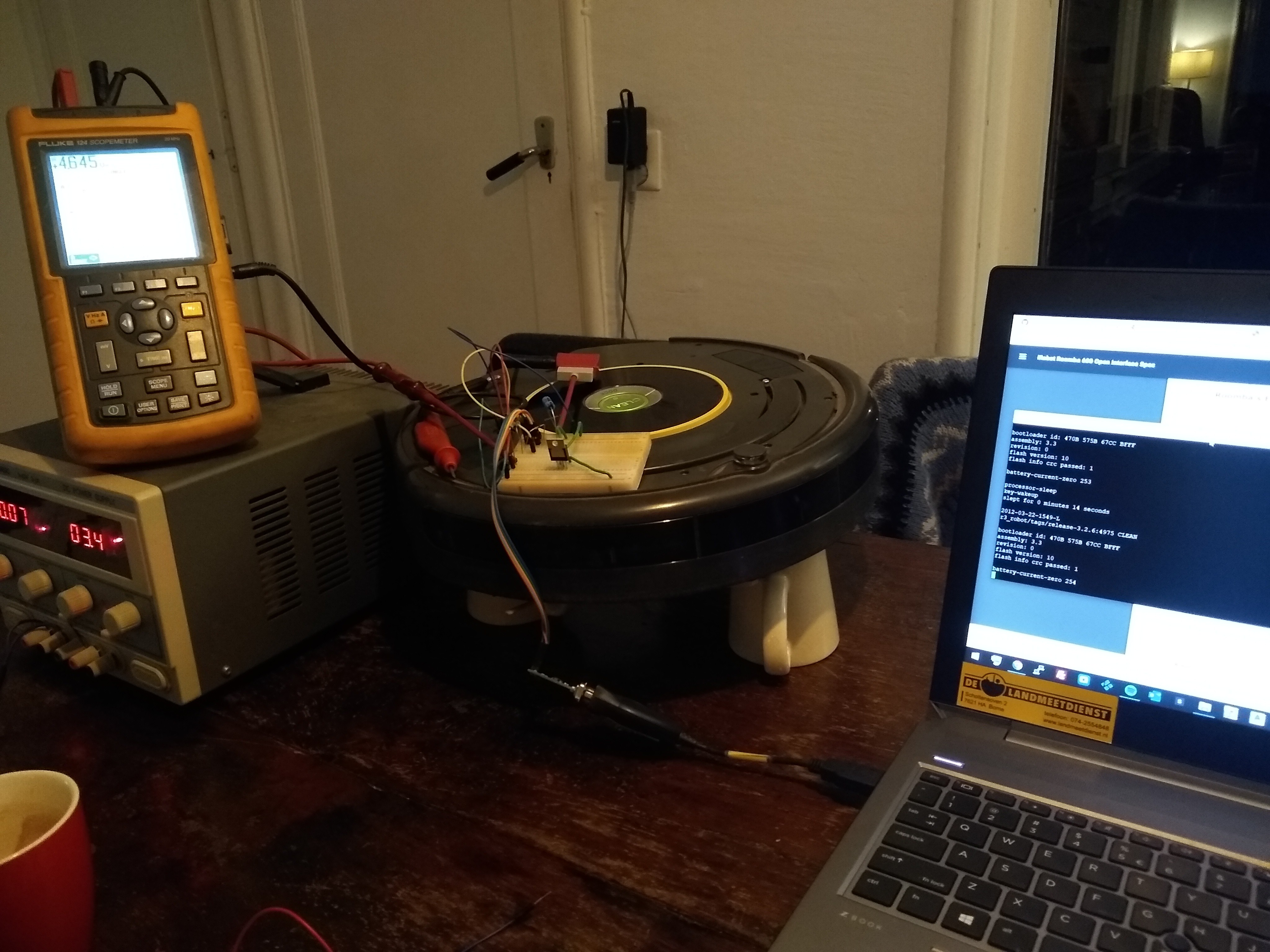
Now, when I connect it to my laptop I get the following message when it is turned on:
key-wakeup
slept for 0 minutes 12 seconds
2012-03-22-1549-L
r3_robot/tags/release-3.2.6:4975 CLEAN
bootloader id: 470B 575B 67CC BFFF
assembly: 3.3
revision: 0
flash version: 10
flash info crc passed: 1
battery-current-zero 254
This tells me I have the correct firmware version. It has the Open Interface and I won't have any problems with a sleep state when charging.
Now to send commands. The interface expects raw byte data. No ASCII-characters or any formatting. This can't be done with the serial monitor provided with the Arduino IDE.
You need something like Realterm (https://realterm.sourceforge.io/) with this, you can send single bytes.
I thought it wasn't responding to any input at first. You send it byte 128 to start the interface and then you can command it to go in a 3 'modes'. 'passive', 'safe' or 'full'.
I had it on some axle stands/coffee cups so it wouldn't spontaneously drive of my table. It took me quite a while to figure out why it wasn't responding to my commands. But it turns out to be because of the dropped wheels! When it is in 'safe mode' and it senses a wheel being dropped it will revert to 'passive mode'. Because of the wheels being dropped, it needed to operate in 'full mode' to accept drive commands.
In mandatory hacker-voice:
"we're in!"
Discussions
Become a Hackaday.io Member
Create an account to leave a comment. Already have an account? Log In.