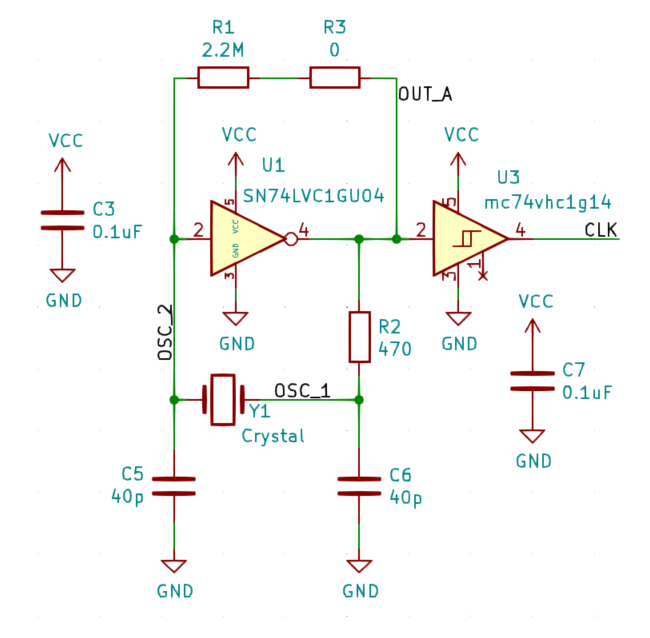
The external clock for this widget is a Peirce Oscillator (shown in below). Calculations for component selection of C5/C6 and R2 are outlined in the project HAS. Note that R3 was added to allow for tweaking of the feedback resistor. Something I learned here is that a Schmitt trigger in place of U1 can cause the clock to intermittently fail. It sounds like this behaviour is caused by the uncertain thresholds off the Schmitt trigger. For example, for the MC74 IC the negative threshold @5V Vcc has a min threshold of 1.65V and a typical threshold of 2.9V.
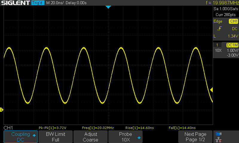
Here's a few scope captures of this circuit in operation. The signal OSC_2 going into pin 2 of U1 is a nice sinusoid seen below
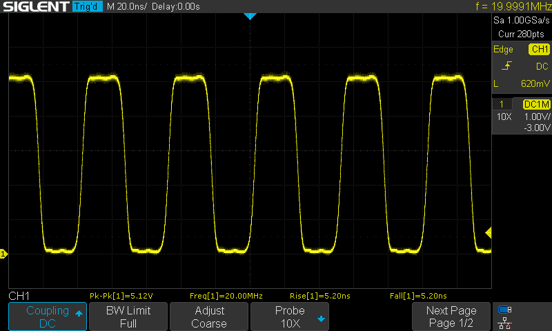
Here's the output of the first inverter; pin 4 of U1. As is, the clock is looking pretty clean, and would likely be fine to drive the Attiny.
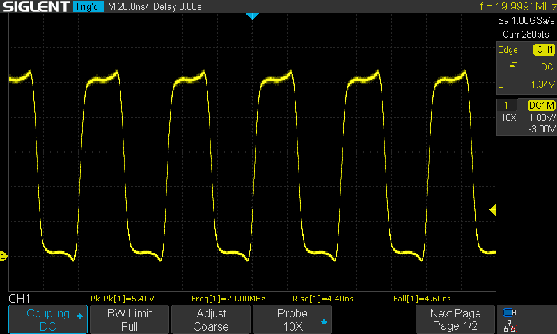
After the buffered inverter the clock edges are tightened up a bit more, but we’ve also introduced a bit of overshoot (There's a good chance my oscilloscope [1104X-E] is filtering the edges of this clock signal a bit). It might be a good idea to remove U3 to help reduce BOM cost.
Discussions
Become a Hackaday.io Member
Create an account to leave a comment. Already have an account? Log In.