Jacob David C Cunningham
-
Something new
05/11/2022 at 07:34 • 0 commentsI seem to keep doing the same thing over and over again with regard to reworking the gaits/checking mesh plots.
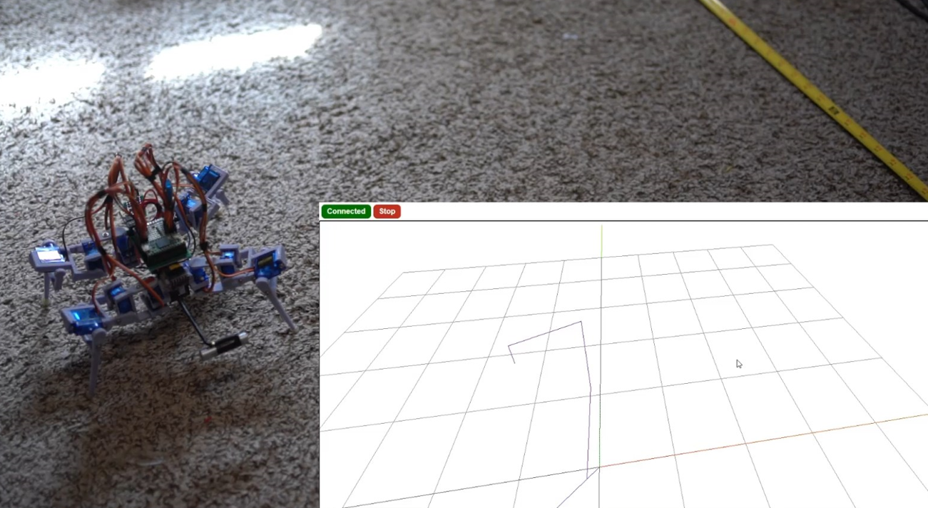
So here immediately is something new. The depth sensing box plotting as the robot encounters obstacles using ThreeJS.
Yes it plotted the second box in the wrong place but overall the project is making bigger strides. I have to work out the translation/back tracking. And also really nail down the obstacle part because it's using the old code that was bad, hence it's not quite accurate.
Longer video
I have to clean up the above.
Next thing will be to import the 3D model of the robot using glTF export from SketchUp and then moving each part. I think I will have to import each moving joint/position them in 3D space, then I can use JS to move them/show the gaits in ThreeJS.
Then improve the UI as it's a piece of crap currently.I'm going to focus on "finishing" this project because I need to move my mind away from projects for a bit/focus on some work stuff I'm about to go bankrupt yo! lol semi-joking (but I do have to job search after this month). Gotta grind that leet/DSA as they say.
-
First attempt at obstacle detection
04/28/2022 at 20:01 • 0 comments![]()
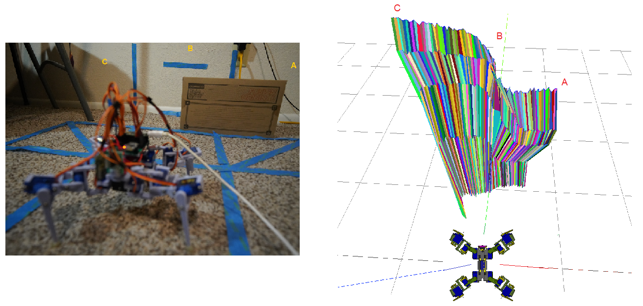
I made a basic navigation algo, it just checks if any samples are within 18" and if it happens more than a certain number of times (in case of bad ToF measurements). It still needs work. This does not include the IMU. The sampling is very course. The beam is narrow, so often the outer legs run into something... I tried to correct that later by increasing the sensing distance threshold eg. from 12" away to 18".
At this time I have to replace all of the servos on this robot because many of them died. I think primarily from when it was running into a wall/tipped over and it had to push itself back upright. Overall I've mentioned before my disappointment in this robot due to picking cheap parts (weak servos, inaccurate sensors). But hey, that's what you get for 75% off (servo price). I'm half tempted to find 9G servos with the exact same dimensions but are more powerful/possibly using metal gear however I can't guarantee that they're actually good (unless I buy from someone like Adafruit I suppose). Ultimately I'm also not sure if it's worth dumping more money into this project. I do want to follow through with the software and finish the slated goals.
Here's a long video talking about the first obstacle detection "algo" and then the various trials.
I mostly had dumb lazy code mistakes. I think I can polish it up/make it work decent, with the IMU correction for stall/being stuck that can help improve its reliability. I had another thought too where an overhead camera/server would steer it.
There are obvious improvements to make like pre-emptively terminating the rest of a sweep sample if I already found something in the way. This is a very crude/coarse obstacle detection, if something's detected that's treated as a big cube that the robot has to go around. I don't know about the dimensions yet.
-
Still working on this
04/27/2022 at 02:31 • 0 commentsI kind of ran out of time today but I am working on it.
I have decided to move forward with the gaits that I have now (Regis Hsu 2017 spider robot) and current sampling pattern.
I took some measurements today, I am working on a C++ based "algorithm" to process the 5 sample planes for the obstacle detection/box-bounding.
This is top of my project priority again I just wanted to get outside/had to finish my camera external display project and also do day job. I also fixed my DLG but need to design a carrier for it.
![]()
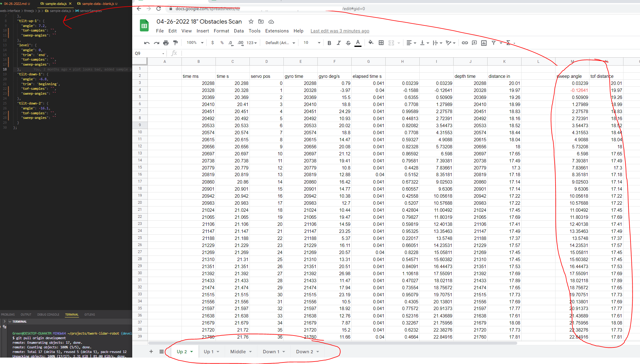
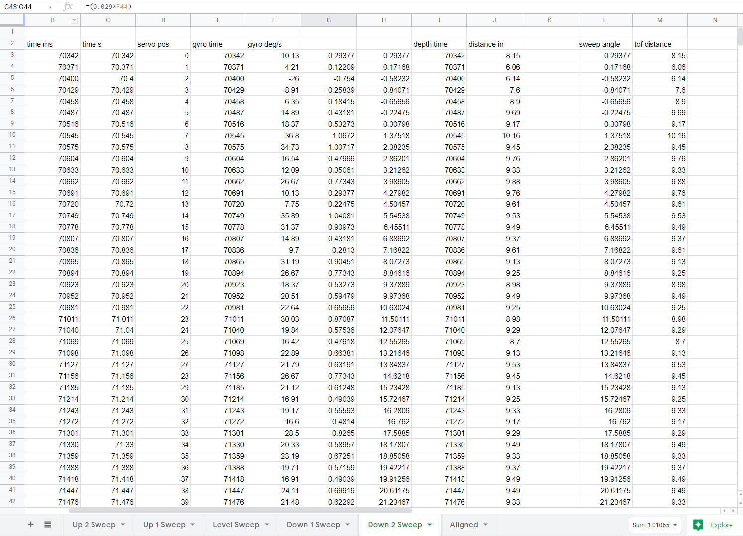
I'm also done doing these samples for the Three JS it's too much data to transmit with the ESP-01, keeps having buffer problems, so I'm doing all the math on the Teensy then sending basic coordinates/sizes of box-obstacles.
Can see below what I do to make the mesh plot above.
![]()
mesh-plot.html chews through the right-side numbers on the left and creates the mesh above.
I also have not fixed the offset orb deal with the ToF sensor.
-
Sadness, a small update
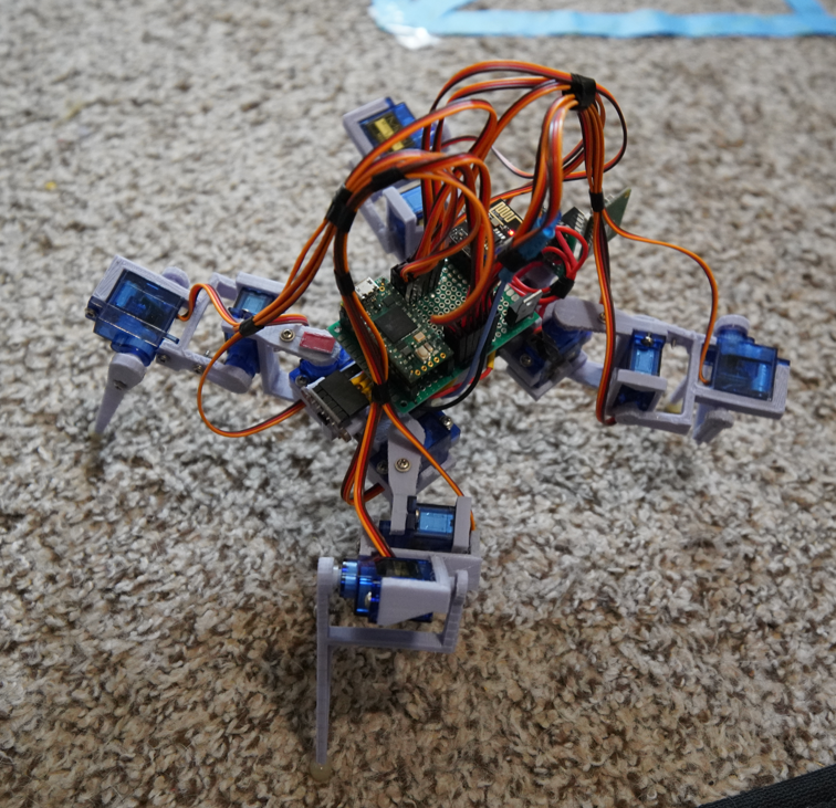
03/09/2022 at 23:04 • 0 comments![]()
it is carrying a weight to reduce the backwards tipping.
Needs work
Well, what started out as a cool/fun project ended up in disappointment, just because of all the inaccuracies/weak parts/etc...
What I aimed to do was to get the tracking to work as it moved. But progressively it just kept getting worse and worse, where I was just using hardcoded values vs. what the IMU would read.
Also I burned too much time trying to rework the gaits; the reason being the robot would not walk straight... I ended up going with Regis Hsu's Spider Robot walking and turning gait. I watched a few of his videos at 0.25x speed to see how it moved. While it works well for moving forward/covering a lot of ground eg. 2 inches per gait, it has this problem where it tips backwards to one corner. And that's probably just due to my robot's geometry but yeah... I'm just annoyed with how crappy this robot is.
The ToF sensor is also problematic, I usually always get at least a few bad readings... which you would try to work around/"smoothen" but it's like, what if there is actually a stick there/it's not a mistake? The problematic measurements seem to occur more for the "infinity" case where you're scanning open space. I am using default which caps out at 1.2 meters. The issue I'm talking about though is where it will just randomly say 0 or some really low number when it should be more than 3 feet away.
This is a time consuming project and unfortunately every error/inaccuracy adds up to where the whole thing is pointless so yeah... just a good reminder to not half-ass things.
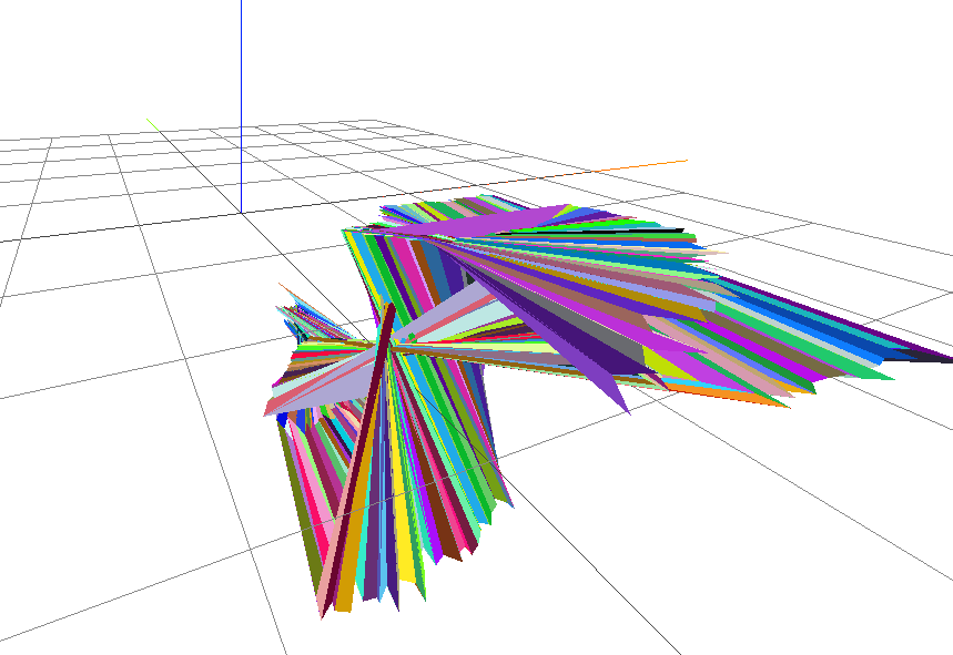
![]()
This is a scan in open space, the bottom pink triangle is an example of a random weird measurement (should be a flat plane viewed from the side).
This is the last thing I have to do in another update is to do the actual ray-polygon collision stuff based on the mesh above. And plotting cubes. I also have to clean up that ThreeJS code, it's so bad... just throw things in there/get it to work.
Also today while I was messing around I wasn't watching the robot and after it turned/somehow two of the servos burned out... like the plastic almost melted (could smell something and was hot to touch) so that was great.
The ESP-01 bridge is also problematic, I did figure out part of the problem (needing to use Serial.flush()) but aside from that, there's still a build up and eventually the ESP crashes. So the comms need work too.
I have been distracted as well the last couple of days. I got the Pinephone Pro Explorer Edition in and I was messing around with that. I have to focus the next several days/week to get some work done. I wanted to get to an "end state" of this project for a week or two before I returned back to it. I need to wrap it up though.
Next update
As mentioned above will include more ThreeJS work and some other improvements that I'm too tired to do now.
The next robot
It will have positional feedback on the legs, current draw spike detection, better IMU, will use a vision system eg. VIO. Will possibly still use a dedicated pan/tilt lidar assembly, arguable with a good enough VIO you don't need it but it would be a cool unit to build, maybe as a stand alone.
Also inverse kinematics or non-manually-programmed gaits would be nice.
-
Small update: Pan-tilt mesh plotting in ThreeJS
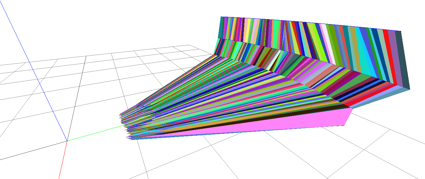
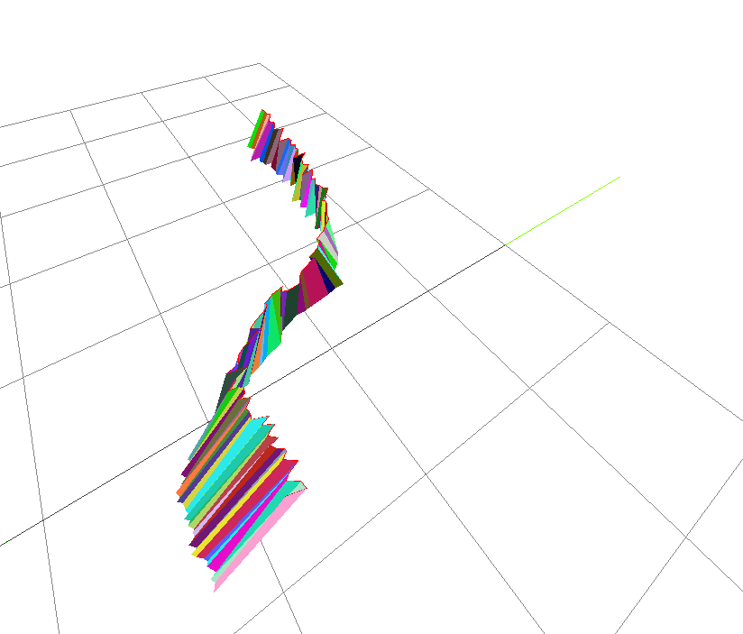
02/18/2022 at 06:03 • 0 comments![]()
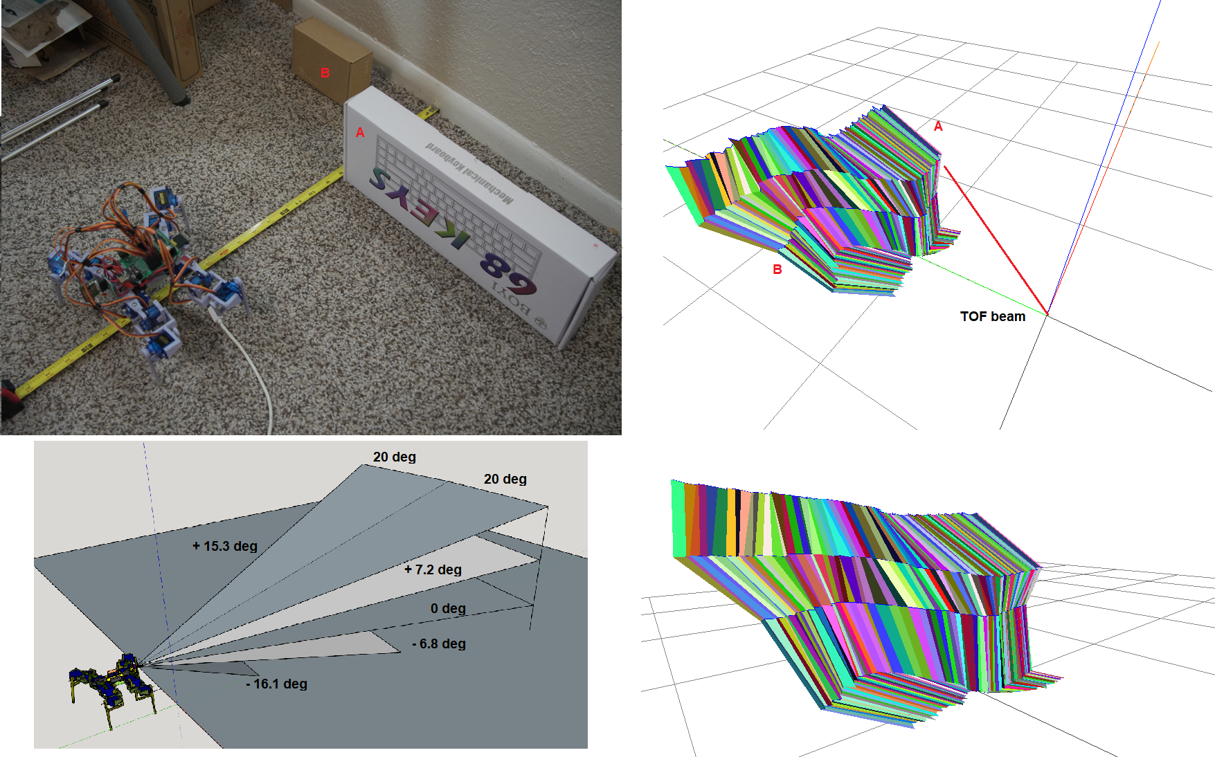
The robot performed 5 angle tilts: 12.3, 6, 0, -7.4, -13.9 with the ToF sensor being 3.38" above the ground. There were 100 samples per angle (50 on either side of Y axis green) resulting in the mesh above. It is not accurate due to the ToF sensor shifting as part of the robot's geometry.
The robot on the bottom right is not to scale. The blue squares are 1 ft so robot is 1.5' away from the box. Robot is 8.5" cubed roughly.
I used the multi-color panels because just a solid color it's hard to tell without shading the depth.
I will admit this took me way too long to do. I had the basics down, how to plot a line (3 points) and a plane (4 points). But this was super problematic as you can see below in my initial tries.
Oh yeah the bottom left of the plot, I believe that's the ToF sensor hitting the robot's own leg. So that would be an outlier to take out.
![]()
I had to start simple and use the lines/plane samples and check that the points lined up.
There is also a lot of data to organize/sort into something that makes sense from the IMU/ToF measurements.
![]()
![]()
This is a lot of data, it's 500 points which is 1500 coordinates. A lot with regard to the ESP-01 sending that data by Serial/Websocket. So I will simplify the "real time telemetry" as cubes (bounding boxes) and their location in 3D space with respect to the robot's initial 0, 0, 0 position and where it's been (linear accel/rotation velocity sum tracking).
There is unfortunately a lot of sources of error with this project. I have messed around with for example magnetometer calibration but have not calibrated the accelerometer. The sweep movement needs to include the outer legs, currently it sways around. I fixed the pitch because there it was very bad.
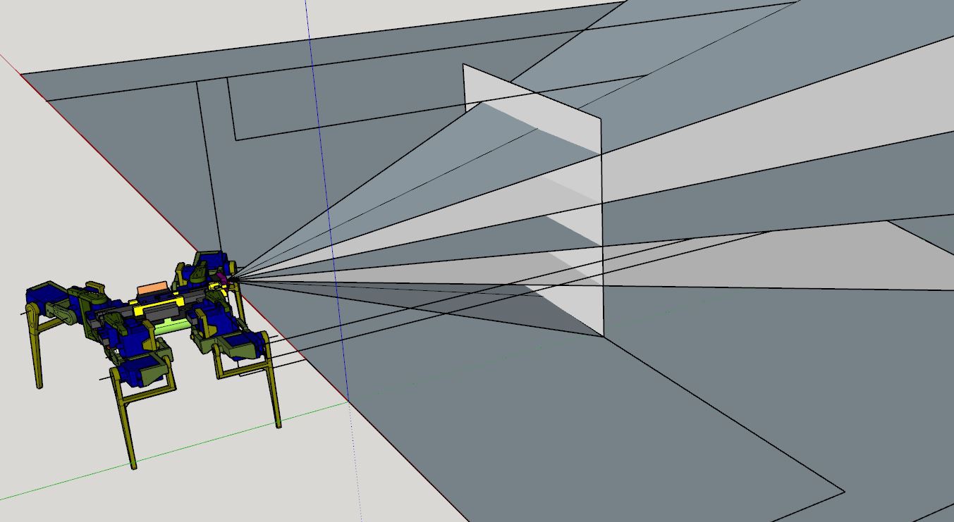
I could not get the pitch angle from the gyro x or NED (harder math) so I just used external visual measurements using a camera/SketchUp to measure the pitch angles.
![]()
Also when the robot moves the ToF sensor also moves in 3D offset, so the measurements above are not showing a straight face of the box, it has a slant.
Anyway it's progress. I got side tracked with another software project and also my day job but I want to finish this within February because I will have received the Pinephone Pro hopefully sometime then and that'll be the next thing I work on.
I will keep working on robots I have a new one in mind (think the Star Wars homing spider droid). I just thought about it when I was messing with a tripod for my camera, those could be it is legs and uses a pinion rack type gear to raise/lower them. Mainly though it would be big, as in be able to move at speed/cover ground and definitely overcome human obstacles eg. laundry on the floor, random plastic bags, boxes, etc... it also would feature better parts/better math. I will dump some time into the IMU stuff to really get that down.
But this also means a lot of money as I'm done buying cheap parts.
Anyway I will keep working on this, there's still some stuff to do, this is just ThreeJS visual stuff, the navigation will actually occur in the robot eg. the Teensy.
This math is still useful/I'll translate it into C++ from JS and use it for the mesh collision math (that's what I think at this time anyway).
-
Update on project, still not navigating yet but closer
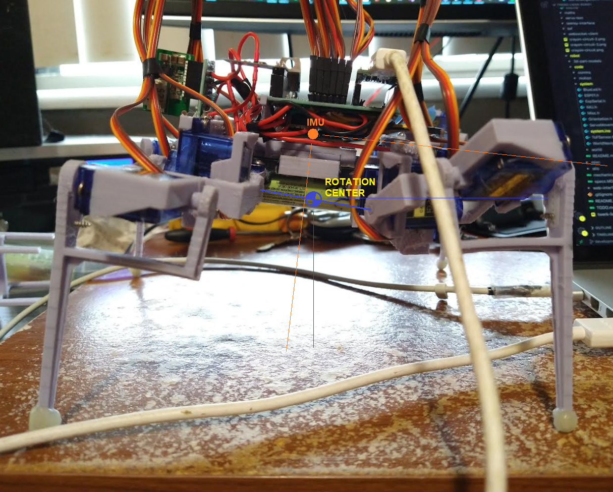
02/01/2022 at 03:42 • 0 comments![]()
I have broken one of my own rules (ego posting), forgive me
At this point I have figured out the NED coordinate frame, what does this mean/how will I use it? Not sure yet but I can tell which way is down, there is that.
I've also been working with the gyro to determine the pitch and sweep angles. It is funny that the measured values went against what I assumed and I was able to prove that they were "correct" with an external check eg. video scenes and a CAD program.
I have to update some gaits/do more data collection. Then I have to put all of the code together. Then see how it tracks/loses accuracy in the real world.
Video below, audio is kind of weak I'm tired/can't be too loud where I'm at. I just recently uploaded it so the quality might not be good yet.
Oh I forgot to mention, the blue LED is for calibration, like if you're calibrating the magnetometer it will flash a few times to tell you to prepare then go solid as you rotate it about an axis (in XYZ order).
Next day thought:
I do feel regretful with this design, mostly because of oversight like the ToF sensor needing 20ms to get a sample. It just means the servos are stuck in high-torque situations longer... the yellow area above is like an ideal scenario but really I'm working with slices. The more tilt samples I do the better data I have.
Anyway I have a Pi Zero 2 and the data streaming stuff for the world telemetry will be much better.
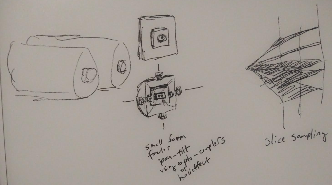
I'll think about how a small form-factor pan-tilt system with some kind of encoder setup to tell where it is with small servos. I'll also use a 2-cell setup as that seems to be more standard vs. stepping up from a single cell. I also want to find stronger servos vs. these cheap 9G servos that are weak/easy to strip.
Oh yeah not pictured below but you would need to use a slip ring for the sensor to move freely. It would need the 4 lines (VCC, GND, SCL, SDA) to use the ToF sensor.
![]()
Twerk Lidar Robot
An insect-quad style robot with an IMU plus ToF lidar sensor for mapping and navigation.