 Sagar 001
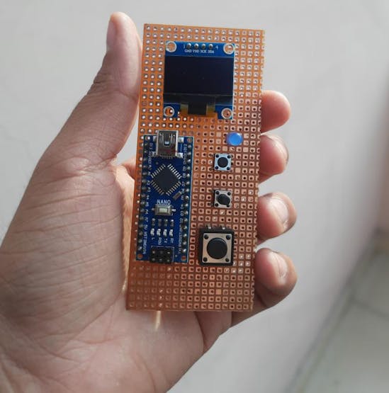
Previously, I posted a tutorial on Raspberry Pi-Pico Oscilloscope. And that was a great success. Keeping portable options in mind, I found this pretty mini oscilloscope between thousands of pages of a Japanese website. We are using a mini-OLED 128X64 to display the signal waveform, Frequency, duty cycle. 4 tactile buttons are used to change the modes, Volts/Divisions, and time/Divisions. So, I tried this, and the results are here.
Note* This project is only for educational purposes and shows the capabilities of a 16Mhz 8-bit microcontroller board. This MCU Can support frequencies below 50KHz, so it can’t be applicable for commercial and professional uses. That way, the project can also be entitled POOR MAN OSCILLOSCOPE for me.
Arduino Nano/Uno:
Both the boards have the same 8-bit Atmega328p microcontroller to use any of them. This tutorial uses I2C communication to print the readings on an OLED display. Our microcontroller has 6-channel 10-bit ADC, 13 digital I/O pins, and an 8Mhz internal clock.
That's why I tried the project on breadboard first. I want to know the plus/minus points of this oscilloscope. This project is sponsored By JLCPCB, Pcb, code and circuit diagram to this project is given below. Download all Gerber file from here and Quote for PCB on JLCPCB just in $2, On first sign-up from here you will get worth $30 coupons to order PCB.
For PC: https://jlcpcb.com/SSRFor mobile phone: http://m.jlcpcb.com/ssi
Features:
- Single-channel -20Khz bandwidth
- Onscreen- Volt/Div and Time/Div
- Duty cycle monitoring
- Small 0.96-inch I2C
- AC/DC measurements option
- Mode changing, Hold state features
- Low battery consumption
- Portable and pocket-sized
Display:

0.96-inch OLED display with I2C function comes with two different models, SSD1306 and SH1106, to change the code as per requirements. We have to uncomment which version of LCD we are using in this project.
Components used:
- Arduino Nano
- 128X64 OLED display
- 100k, 10k, 820k, 510k, 12k resistors
- 100nf, 7pf, 1uf ceramic disc capacitors
- Tactile switch x4
- Breadboard
- Connecting wires
Circuit diagram:

Circuit description:
After making all the connections, this oscilloscope can be powered by a 5v @100mA power supply or 3.7 volt Battery. Significantly fewer external components are used in this project; also, it supports several actions. Here MODE button is to select the volt/div, time/div, AC/DC, and 180* wave settings.

After selecting the Mode, we can either increase the value or decrease per wave format. For Volts/divisions: This oscilloscope supports a division from 0.2volts to 50volts.
For Time/Div: Code is modified to display small divisions in microseconds, 1.56 microseconds to 200milli-seconds.

Measurements:
- With 50Hz sine wave:

I tried to hook upthis oscilloscope directly with Step down transformer AC signal and here are the results:

- With 300HZ sine wave:

- With triangular wave:

- With rectangular wave:

- With sawtooth wave:

Libraries used:
OLED display SSD1306, SH1106, Fix_fft and EEPROM libraries are available in Arduino Mange library section. From here you can download as per your needs.

PCB:
Download all the material regarding this project from here.

Conclusion:
This oscilloscope is suitable for analyzing waveforms between 10Hz to 20Khz. That is precisely human hearing frequency. So, we can use this to measure audio signals, amplifier signals, and different Bluetooth signals. This oscilloscope should be a good try for them. Also, I think precision matters a lot in signals. If you want to go professional but cheaper, I would recommend DSO138. But this is about 4x the cost of this Arduino oscilloscope, but this one has an analog frequency range of 200khz.

In comparison with This DSO, I have An Article about Raspberry Pi- Pico Oscilloscope, which offers android application compatibility, 2-channel, and 200khz frequency range. See this PI-PICO Oscilloscope from here.
About JLCPCB:
JLCPCB is the one of the most popular PCB makers. Price is just $2 for 2, 4 and 6 layer PCB. They just launched new purple solder mask, aluminum Pcb and 3d printing service in very low cost. Pcb quality is not compromised at any cost. Check them out right now from Here.

JLCPCB Is also providing new user coupons and sign-up rewards of up to $30. So, check them out from here. Register using this link to get Free PCB assembly service coupons. Get your 2 layer to 6-layer PCB’s just in $2, stencil and PCB assembly service in just $7.
For PC: https://jlcpcb.com/SSRFor mobile phone: http://m.jlcpcb.com/ssi

Gallery:

Updates:
We are trying to use a big touch TFT color screen with a high resolutions, So the project will be updated as soon as possible till then keep supporting us, we did not want any type of financial support, just follow us.

More projects:
1) How to make Arduino Uno clone board.
2) How to program Arduino Using Smart Phone.
3) Arduino Nano clone board problems and solutions.
4) How to make Inductance Meter Using Arduino.
5) Raspberry Pi- PICO Oscilloscope.
Think you enjoy my work, stay tuned. Follow us on Instagram (sagar_saini_7294) and hackaday.
please support us- No donations, just follow and leave a comment.
Code: Code is quite bit long so we added small shots notes on each section, this will help you to understand
// Follow us on Hackster, Hackaday and the Instructables.
//Please First uncomment/comment the oled driver lines, which you are using
//Circuitkicker.com -- Sagar saini --sainisagar7294
#include <Wire.h>
#include <Adafruit_GFX.h>
#include <Adafruit_SSD1306.h>
//#include // https://github.com/wonho-maker/Adafruit_SH1106
#include <EEPROM.h>
#define SCREEN_WIDTH 128 // OLED display width
#define SCREEN_HEIGHT 64 // OLED display height
#define REC_LENG 200 // size of wave data buffer
#define DISP_LENG 100 // size of display data
#define MIN_TRIG_SWING 5 // minimum trigger swing.(Display "Unsync" if swing smaller than this value
#define DOTS_DIV 25
// Declaration for an SSD1306 display connected to I2C (SDA, SCL pins)
#define OLED_RESET -1 // Reset pin # (or -1 if sharing Arduino reset pin)
Adafruit_SSD1306 oled(SCREEN_WIDTH, SCREEN_HEIGHT, &Wire, OLED_RESET); // device name is oled
//Adafruit_SH1106 oled(OLED_RESET); // use this when SH1106
#define R_12k 4 // 12k ohm
#define R_820k 16 // 820k ohm for AC low range
#define R_82k 17 // 82k omm for AC Hi range
// Range name table (those are stored in flash memory)
const char vRangeName[10][5] PROGMEM = {"A50V", "A 5V", " 50V", " 20V", " 10V", " 5V", " 2V", " 1V", "0.5V", "0.2V"}; // Vertical display character (number of characters including \ 0 is required)
const char * const vstring_table[] PROGMEM = {vRangeName[0], vRangeName[1], vRangeName[2], vRangeName[3], vRangeName[4], vRangeName[5], vRangeName[6], vRangeName[7], vRangeName[8], vRangeName[9]};
const char hRangeName[22][6] PROGMEM = {"200ms", "100ms", " 50ms", " 20ms", " 10ms", " 5ms", " 2ms", " 1ms", "500us", "200us", "100us", " 50us", " 81us", " 41us", " 20us", "156us", " 78us", " 31us", "15.6u", "7.8us", "3.1us", "1.56u"}; // Hrizontal display characters
const char * const hstring_table[] PROGMEM = {hRangeName[0], hRangeName[1], hRangeName[2], hRangeName[3], hRangeName[4], hRangeName[5], hRangeName[6], hRangeName[7], hRangeName[8], hRangeName[9],
hRangeName[10], hRangeName[11], hRangeName[12], hRangeName[13], hRangeName[14], hRangeName[15], hRangeName[16], hRangeName[17], hRangeName[18], hRangeName[19], hRangeName[20], hRangeName[21]};
const float hRangeValue[] PROGMEM = { 0.2, 0.1, 0.05, 0.02, 0.01, 0.005, 0.002, 0.001, 0.5e-3, 0.2e-3, 0.2e-3, 0.2e-3, 81.3e-6, 81.3e-6, 81.3e-6, 156.25e-6, 78.125e-6, 31.25e-6, 15.625e-6, 7.8125e-6, 3.125e-6, 1.5625e-6}; // record speed in second. ( = 25pix on screen) this value used for freq calc.
int waveBuff[REC_LENG]; // wave form buffer (RAM remaining capacity is barely)
char chrBuff[8]; // display string buffer
char hScale[] = "xxxAs"; // horizontal scale character
char vScale[] = "xxxx"; // vartical scale
float lsb5V = 0.00563965; // (5V)sensivity coefficient of 5V range. std=0.00563965 1.1*630/(1024*120)
float lsb50V = 0.0512939; // (50V)sensivity coefficient of 50V range. std=0.0512939 1.1*520.91/(1024*10.91)
float lsb5Vac = 0.00630776; // std=0.00630776 V/LSB
float lsb50Vac = 0.0579751; // std=0.0579751 V/LSB
volatile int vRange; // V-range number 2:50V, 3:20V, 4:10V, 5:5V, 6:2V, 7:1V, 8:0.5V, 9:0.2V
volatile int hRange; // H-range nubmer 0:200ms, 1:100ms, 2:50ms, 3:20ms, 4:10ms, 5:5ms, 6;2ms, 7:1ms, 8:500us, 9:200us, 10:100us, 11:50us, 12:
volatile int trigD; // trigger slope flag, 0:positive 1:negative
volatile int scopeP; // operation scope position number. 0:Veratical, 1:Hrizontal, 2:Trigger slope, 3:DC/AC/FFT
volatile boolean hold = false; // hold flag
volatile boolean switchPushed = false; // flag of switch pusshed !
volatile int saveTimer; // remaining time for saving EEPROM
int timeExec; // approx. execution time of current range setting (ms)
int dataMin; // buffer minimum value (smallest=0)
int dataMax; // maximum value (largest=1023)
int dataAve; // 10 x average value (use 10x value to keep accuracy. so, max=10230)
int dataRms; // 10x rms. value
int rangeMax; // buffer value to graph full swing
int rangeMin; // buffer value of graph botto
int rangeMaxDisp; // display value of max. (100x value)
int rangeMinDisp; // display value if min.
int trigP; // trigger position pointer on data buffer
boolean trigSync; // flag of trigger detected
int att10x; // 10x attenuator ON (effective when 1)
int inMode; // 0=DC+, 1=DC+-, 2=AC
int offset5Vac;
int offset50Vac;
float waveFreq; // frequency (Hz)
float waveDuty; // duty ratio (%)
#include <fix_fft.h>
#define FFT_N 128
volatile boolean fftMode = false; // FFT mode false:Wave, true:FFT
void setup() {
pinMode(2, INPUT_PULLUP); // reserve (button press interrupt (int.0 IRQ))
pinMode(3, OUTPUT); // PWM for trigger level
pinMode(R_12k, INPUT); // pin4 1/10 attenuator(Off=High-Z, Enable=Output Low)
pinMode(5, INPUT_PULLUP); // FFT mode
pinMode(7, INPUT_PULLUP); // AC mode
pinMode(8, INPUT_PULLUP); // Select button
pinMode(9, INPUT_PULLUP); // Up
pinMode(10, INPUT_PULLUP); // Calibration pulse output
pinMode(11, INPUT_PULLUP); // Hold
pinMode(12, INPUT_PULLUP); // Down
pinMode(13, OUTPUT); // LED
pinMode(R_820k, INPUT); // A2
pinMode(R_82k, INPUT); // A3
DIDR0 = 0x0f; // disable digital input buffer of A0-A3
oled.begin(SSD1306_SWITCHCAPVCC, 0x3C); // select 3C or 3D (set your OLED I2C address)
// oled.begin(SH1106_SWITCHCAPVCC, 0x3C); // use this when SH1106
auxFunctions(); // Voltage measure (never return)
loadEEPROM(); // read last settings from EEPROM
#define REFERENCE_INTERNAL
#ifdef REFERENCE_INTERNAL
analogReference(INTERNAL); // ADC full scale = 1.1V
trigger_level(26); // PWM triger level 0.5V for ET
#else
analogReference(DEFAULT); // ADC full scale = 5.0V
trigger_level(128); // PWM triger level 2.5V for ET
#endif
(void) analogRead(0); // dummy read to select A0 and reference
#ifdef USE_PIN2IRQ
attachInterrupt(0, pin2IRQ, FALLING); // activate IRQ at falling edge mode
#else
PCMSK0 = _BV(PCINT4) | _BV(PCINT3) | _BV(PCINT1) | _BV(PCINT0); // D8,D9,D12 pin change interrupt
PCICR = _BV(PCIE0); // enable interrupt from PCIE0 group
#endif
startScreen(); // display start message
}
void loop() {
if (hRange < 15) pulse(); // calibration pulse is for realtime sampling only
setInputOffset(); // coupling mode set(AC/DC)
setConditions(); // set measurment conditions
digitalWrite(13, HIGH); // flash LED
readWave(); // read wave form and store into buffer memory
digitalWrite(13, LOW); // stop LED
setConditions(); // set measurment conditions again (reflect change during measure)
dataAnalize(); // analize data
writeCommonImage(); // write fixed screen image (2.6ms)
plotData(); // plot waveform (10-18ms)
dispInf(); // display information (6.5-8.5ms)
oled.display(); // send screen buffer to OLED (37ms)
saveEEPROM(); // save settings to EEPROM if necessary
while (hold == true) { // wait if Hold flag ON
dispHold();
if (inMode > 0) { // if DC mode,
if (acZero() == 1) { // if offset adj. executed
scopeP = 0; // scope position to vartical
hold = false; // cancel hold
}
delay(10);
} //
}
}
int acZero() { // cancel AC renge offset
if (digitalRead(8) == LOW) { // if select pushed
if (vRange >= 5) { // = 5V or less
offset5Vac = dataAve / 10; // adjust the offset
} else { // range more than 5V
offset50Vac = dataAve / 10; // adjust the offset
}
saveEEPROM(); //
return 1; // adjusted
}
return 0; // no adjust
}
void setInputOffset() { // set offset circuit
if (inMode >= 1) { // if AC mode
if (att10x == 1) { // 10X-att enabled
pull5V(R_82k); // ‹ pull 5V by 82k
hiZ(R_820k);
} else { // 10X-att disable
hiZ(R_82k);
pull5V(R_820k); // pull 5V by 820k
}
} else { // DC mode
hiZ(R_820k); // Hi-Z
hiZ(R_82k); // Hi-Z
}
}
void hiZ(int n) { // set the pin to hi-z
pinMode(n, INPUT); // set INPUT
digitalWrite(n, LOW); // no pull up
}
void pull5V(int n) { // ‹ pull 5V through registor
pinMode(n, OUTPUT); // set OUTPUT
digitalWrite(n, HIGH); // OUTPUT HIGH
}
void pullGND(int n) { // pull GND through registor
pinMode(n, OUTPUT); // set OUTPUT
digitalWrite(n, LOW); // output LOW
}
void setConditions() { // measuring condition setting
if (digitalRead(7) == LOW) { // set AC/DC
inMode = 1; // ƒ‰
} else {
inMode = 0; //
}
// get range name from PROGMEM
strcpy_P(hScale, (char*)pgm_read_word(&(hstring_table[hRange]))); // H range name
strcpy_P(vScale, (char*)pgm_read_word(&(vstring_table[vRange]))); // V range name
switch (vRange) { // setting of Vrange
case 0: // 削除ã—ãŸã€delaeted Auto50V range
att10x = 1; // use input attenuator
break;
case 1: // 削除ã—ãŸã€delaeted Auto 5V range
att10x = 0; // no attenuator
break;
case 2: // 50V range
if (inMode == 0) {
rangeMax = 50.0 / lsb50V; // set full scale pixcel count number
rangeMaxDisp = 5000; // vartical scale (set100x value)
rangeMin = 0;
rangeMinDisp = 0;
} else {
rangeMax = offset50Vac + 25.0 / lsb50Vac; // set full scale pixcel count number
rangeMaxDisp = 2500; // vartical scale (set100x value)
rangeMin = offset50Vac - 25.0 / lsb50Vac;
rangeMinDisp = -2500;
}
att10x = 1; // use input attenuator
break;
case 3: // 20V range
if (inMode == 0) {
rangeMax = 20.0 / lsb50V; // set full scale pixcel count number
rangeMaxDisp = 2000;
rangeMin = 0;
rangeMinDisp = 0;
} else {
rangeMax = offset50Vac + 10.0 / lsb50Vac; // set full scale pixcel count number
rangeMaxDisp = 1000;
rangeMin = offset50Vac - 10.0 / lsb50Vac;
rangeMinDisp = -1000;
}
att10x = 1; // use input attenuator
break;
case 4: // 10V range
if (inMode == 0) {
rangeMax = 10.0 / lsb50V; // set full scale pixcel count number
rangeMaxDisp = 1000;
rangeMin = 0;
rangeMinDisp = 0;
} else {
rangeMax = offset50Vac + 5.0 / lsb50Vac; // set full scale pixcel count number
rangeMaxDisp = 500;
rangeMin = offset50Vac - 5.0 / lsb50Vac;
rangeMinDisp = -500;
}
att10x = 1; // use input attenuator
break;
case 5: // 5V range
if (inMode == 0) {
rangeMax = 5.0 / lsb5V; // set full scale pixcel count number
rangeMaxDisp = 500;
rangeMin = 0;
rangeMinDisp = 0;
} else {
rangeMax = offset5Vac + 2.5 / lsb5Vac; // set full scale pixcel count number
rangeMaxDisp = 250;
rangeMin = offset5Vac - 2.5 / lsb5Vac;
rangeMinDisp = -250;
}
att10x = 0; // no input attenuator
break;
case 6: // 2V range
if (inMode == 0) {
rangeMax = 2.0 / lsb5V; // set full scale pixcel count number
rangeMaxDisp = 200;
rangeMin = 0;
rangeMinDisp = 0;
} else {
rangeMax = offset5Vac + 1.0 / lsb5Vac; // set full scale pixcel count number
rangeMaxDisp = 100;
rangeMin = offset5Vac - 1.0 / lsb5Vac;
rangeMinDisp = -100;
}
att10x = 0; // no input attenuator
break;
case 7: // 1V range
if (inMode == 0) {
rangeMax = 1.0 / lsb5V; // set full scale pixcel count number
rangeMaxDisp = 100;
rangeMin = 0;
rangeMinDisp = 0;
} else {
rangeMax = offset5Vac + 0.5 / lsb5Vac; // set full scale pixcel count number
rangeMaxDisp = 50;
rangeMin = offset5Vac - 0.5 / lsb5Vac;
rangeMinDisp = -50;
}
att10x = 0; // no input attenuator
break;
case 8: // 0.5V range
if (inMode == 0) {
rangeMax = 0.5 / lsb5V; // set full scale pixcel count number
rangeMaxDisp = 50;
rangeMin = 0;
rangeMinDisp = 0;
} else {
rangeMax = offset5Vac + 0.25 / lsb5Vac; // set full scale pixcel count number
rangeMaxDisp = 25;
rangeMin = offset5Vac - 0.25 / lsb5Vac;
rangeMinDisp = -25;
}
att10x = 0; // no input attenuator
break;
case 9: // 0.2V range
if (inMode == 0) {
rangeMax = 0.2 / lsb5V; // set full scale pixcel count number
rangeMaxDisp = 20;
rangeMin = 0;
rangeMinDisp = 0;
} else {
rangeMax = offset5Vac + 0.1 / lsb5Vac; // set full scale pixcel count number
rangeMaxDisp = 10;
rangeMin = offset5Vac - 0.1 / lsb5Vac;
rangeMinDisp = -10;
}
att10x = 0; // no input attenuator
break;
}
}
void writeCommonImage() { // 共通画åƒã®ä½œç”» Common screen image drawing
oled.clearDisplay(); // 全クリア erase all(0.4ms)
if (fftMode == true) return; // no need for the FFT display
oled.setTextColor(WHITE); // write in white character
oled.drawFastVLine(26, 9, 55, WHITE); // left vartical line
oled.drawFastVLine(127, 9, 3, WHITE); // right vrtical line up
oled.drawFastVLine(127, 61, 3, WHITE); // right vrtical line bottom
oled.drawFastHLine(24, 9, 7, WHITE); // Max value auxiliary mark
oled.drawFastHLine(24, 36, 2, WHITE);
oled.drawFastHLine(24, 63, 7, WHITE);
oled.drawFastHLine(51, 9, 3, WHITE); // Max value auxiliary mark
oled.drawFastHLine(51, 63, 3, WHITE);
oled.drawFastHLine(76, 9, 3, WHITE); // Max value auxiliary mark
oled.drawFastHLine(76, 63, 3, WHITE);
oled.drawFastHLine(101, 9, 3, WHITE); // Max value auxiliary mark
oled.drawFastHLine(101, 63, 3, WHITE);
oled.drawFastHLine(123, 9, 5, WHITE); // right side Max value auxiliary mark
oled.drawFastHLine(123, 63, 5, WHITE);
for (int x = 26; x <= 128; x += 5) {
oled.drawFastHLine(x, 36, 2, WHITE); // Draw the center line (horizontal line) with a dotted line
}
for (int x = (127 - 25); x > 30; x -= 25) {
for (int y = 10; y < 63; y += 5) {
oled.drawFastVLine(x, y, 2, WHITE); // Draw 3 vertical lines with dotted lines
}
}
}
void readWave() { // 波形ã®èªã¿å–ã‚