 Maksym
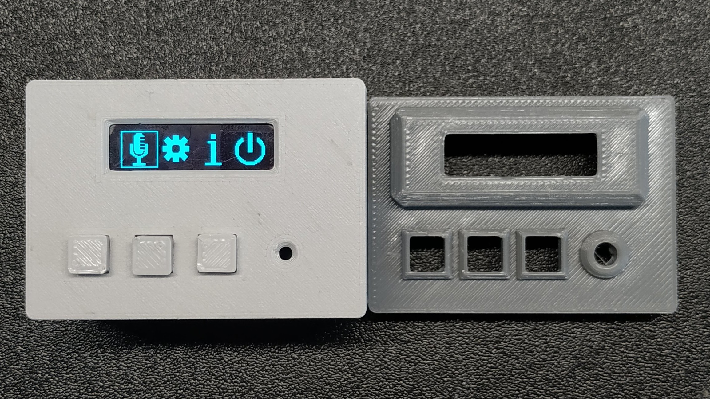
As I said in description first thing I done in this project was simple animated menu. You can see it working at this video:
I didn't have idea for icons so I randomly draw microphone at first and thought to make simple recorder. It utilize almost all pins of the MCU and it's memory. I don't know if this will be possible to be made with HAL. I assumed it will take lot of memory and from beginning made it on registers. However there is some repeated code to optimize. But I will rather use this gained memory to add playback than port it to HAL.
Controls
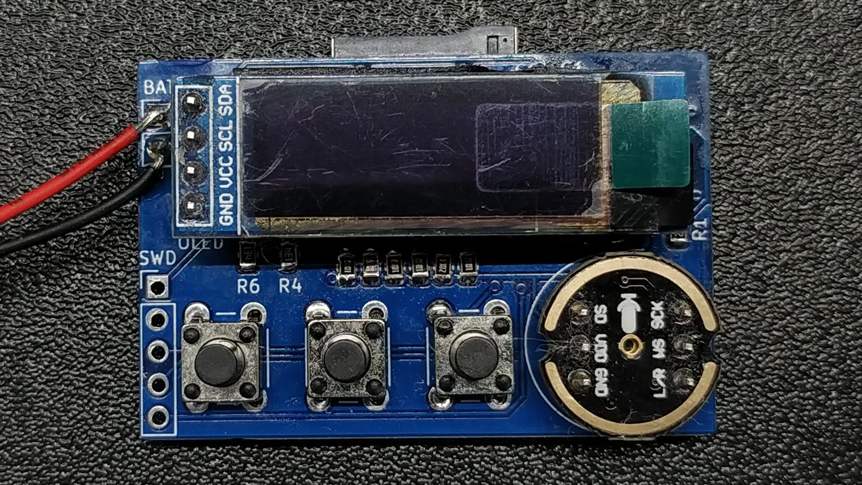
Buttons for control are software debounced and they are triggering interrupt. However I don't think it's necessery. Maybe function called in main when there is nothing else to do will be sufficiant to smooth working of navigation. At first i used four buttons (ok, back, up, down) but later I added "back" as long press of ok. Long press of two other buttons shows battery level.
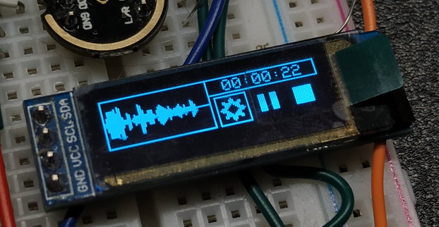
Recording
Recording screen has simple animation that shows average level of sound in last buffor. It also shows recording time at has 3 options. Settings where only setting is gain. But really it not adding any gain but gets more right 16 bits from microphone. (Microphone is giving 24 bit sample but recorder saves only 16 bits so I can ignore some bits from right or left to get different sound level). Other option is play/pause i don't think it's need explanation. And the last option is to end recording. It's only way to do this to avoid accidental stop. I've tested 3 diffrent microSD cards and noticed some things. One from Samsung doesn't want to work at SPI at all. One from "NoName" is working but it's too slow. Recording screen is visable lagging and final recording is also doing it. Best results I had with card form Netac that i have from Ender 3. For communication with SD Card I used FatFs from CUBEIDE with SPI driver from here : https://github.com/kiwih/cubeide-sd-card
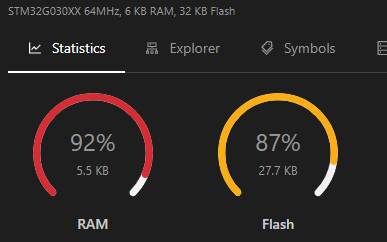
Current consumption
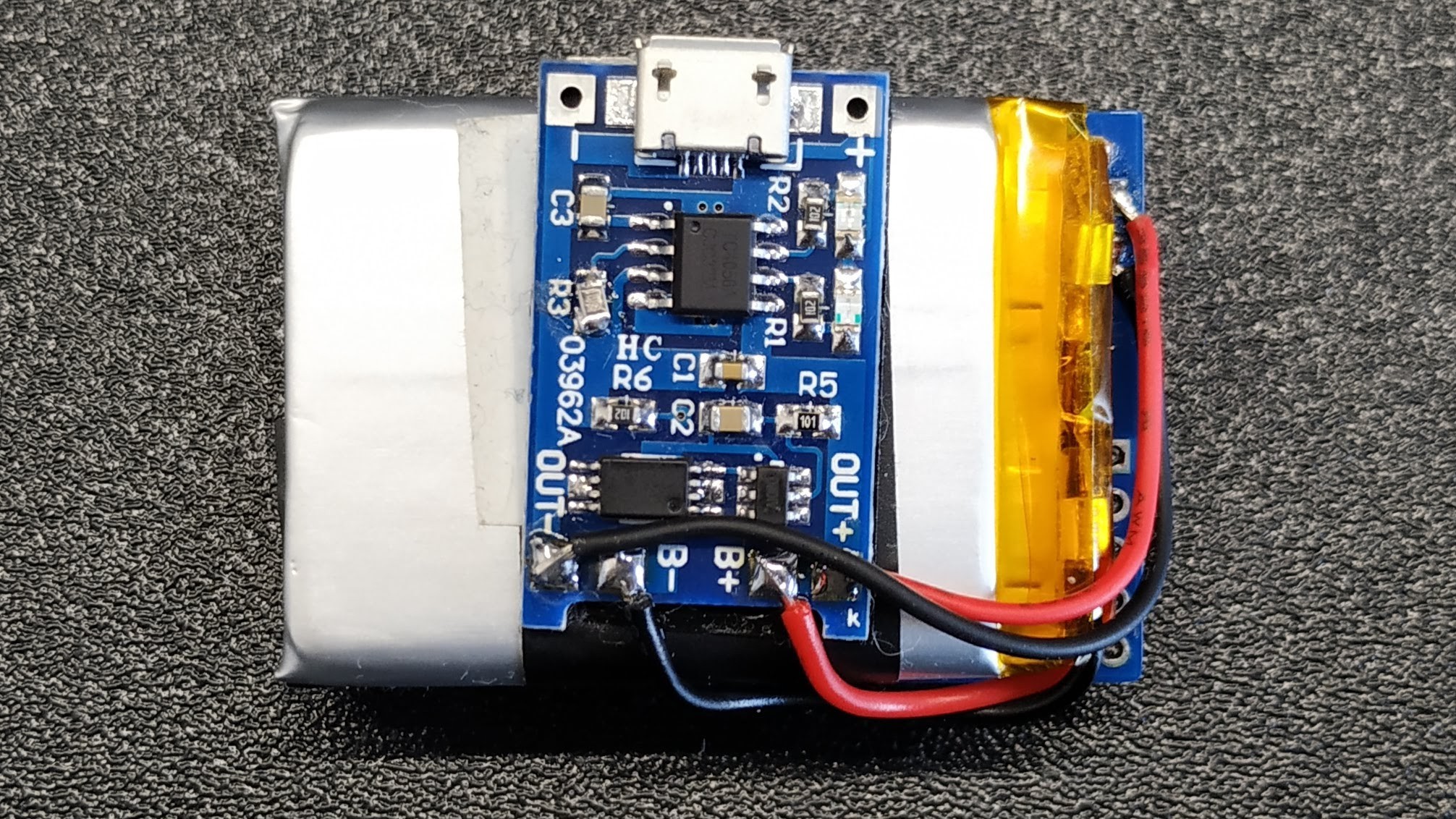
It's will be powered from li-ion battery so current consumption is important thing. When turned on it consumes around 12 mA depending on how many pixels on OLED are on. At recording this value is increased to 16-17 mA, but when saving to memory card there are current spikes up to 60 mA what can be seen on oscilloscope. When turned off, MCU consuption drops to ~2uA. Other things are disconnected from power by MOSFET. However in final form this value will increase due to consuption of LDO and battery protection circuit. I've achive that low current consuption of microcontroller by using standby sleep mode with RTC. Wake up by press of button is possible becouse pin of ok button is same as of one of system wake up pins.
Other
Main settings menu contains options to set time & date, initialize SD card and check free space on card. Icon "i" on main screen contains some informations like microphone type and firmware version however it's kind of random because i wanted icons to be squere and needed four options. Maybe in future it will be replaced with playback option.
 DrYerzinia
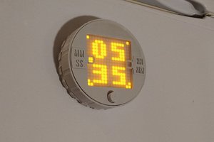
 mkdxdx
 Matias N.
 Xasin
Xasin