 Mark Rehorst
Oops. This wasn't supposed to be published yet, but since the cat is out of the bag, I may as well provide more details.
Please note that I have not received the boards yet so I haven't been able to test the circuit. I am expecting the boards to arrive in a few days and will build one and test it as soon as they arrive.
When I was working on the sand table Arrakis I made a small error and ran the mechanism into the end of the Y axis at 1500 mm/sec. The abrupt stop converted the kinetic energy in the motors to electrical energy that was dumped onto the power supply rail. It happens that I had a Duet controller board and a couple buck converters to power LED strips connected to the same power supply as the motor. You can guess what happened: the power supply, Duet board, and buck controllers all bit the big one, shaving about $200 out of my savings.
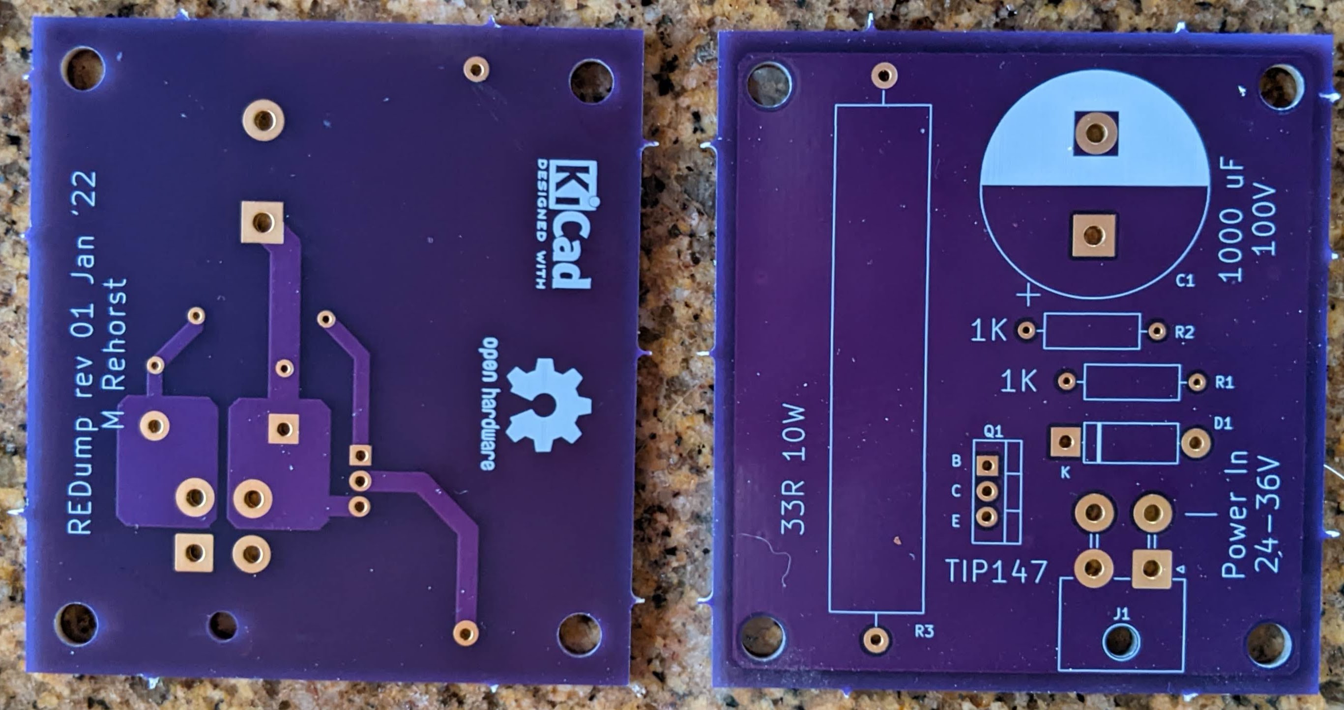
This circuit came from an app note at Gecko Drives. I just selected parts and designed a PCB using KiCAD.
Appnote: https://www.geckodrive.com/support/returned-energy-dump.html
BoM (mine): https://docs.google.com/spreadsheets/d/11N4fHIwaWW3gTsieLKXYEkDYC8u6roJjRu1BrG9OEN0/edit?usp=sharing
Gerber and Drill files: https://drive.google.com/file/d/1ljrtJMXSOWROKx-7XQsDlVD9H4KKbZgh/view?usp=sharing
KiCAD project file: https://drive.google.com/drive/folders/1gcWIDbrikqigsv8qqhZrozVmTr-VLcnQ?usp=sharing
I'm not entirely sure how high the supply voltage can be for this, but the PCB traces and the diode I used are good for 10A continuous. I don't know how high the voltage spike at the motor side will be when the motor is in a fault condition. I use 24V iHSV servomotors so I'm confident this circuit will be fine. It's probably OK for 36V motors, too, but I have no idea if it would be good for 48V or higher motors. R1 may need to be bumped up to 1 or 2W...
Stay tuned for test results...
 DIY GUY Chris
 Daniel Katz
 Kyle Isom
 bobricius