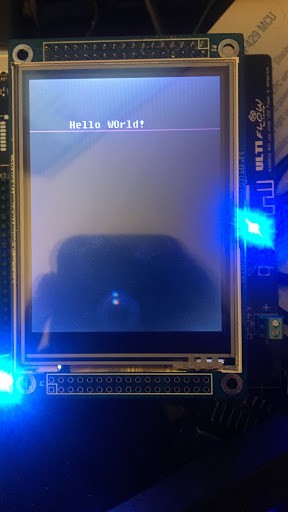
Update 6 (1/11/2017) - uGFX, guis and beyond!
Over the last few days I have been working on getting uGFX baked into my code. As of last night I finally managed to get the library drawing my main menu along with trigger events for the button clicks. So far everything is looking good! I will be flushing out the GUI over the next couple of days and hopefully mounting this bad boy on the oven this weekend to start working on the temperature controller and tuning implementation.
Update 5.5 (1/3/2017) - Board bringup status!
All peripherals are now tested and fully functional. USB VCP is now available along with the SD Card FatFS interface. Over the next week or so I will be flushing out the graphical interface for the project. Since I do not have enough space for a full frame buffer on RAM, I intend to use a contiguous block of memory from the SD card for buffering the screen and displaying the thermocouple data along with buttons to trigger each individual relay from the display.
Update 4 - Woopsies! Rev 2
As I rushed the weekend to create this board, I encountered a couple of mistakes so I took it to address them. The first issue with the board is that I forgot to hook up my SWO pin that is part of the SWD debugger for ST-Link. Luckily this was shared by the SPI3 SCK pin, so i had a nice jumper to one of the two available pads. I changed the temp sensor to the SPI1 bus so that in the future I could use the sensor while debugging. I also added an MT-40 connector for the debugger pins since my pads were tiny and my wires kept breaking.
Update 3 - Arrival and Assembly
The boards arrived along with the parts. While putting it together I noticed I had forgotten to make sure all my parts were 0603 minimum as 0402 just takes way too long to solder by hand. I also noticed i missed a few important connections which will be detailed in a follow-up post once I have tested each of the GPIO.
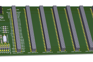
Update 2 - PCB Design
My first revision was pretty horrendous. I used 4 layers to do a quick and dirty job but i found the manufacturing prices for a low volume order too high. I reduced the boardsize so that it was below 10cm x 10cm, re-worked some of the IO so that I could minimize trace crossing and re-designed it into a 2-layer PCB. Now 10 boards cost around $20 from our friendly neighbors in China.
Update 1 - Hardware Selection
The first selection made was the TFT panel since we need to know what kind of interface to provide. I ended up selecting 2 panels, one with regular 100mil headers (Waveshare 3.2in tft ) and the other a bare FPC panel (2.8-3.2in BuyDisplay) both providing a capacitive touch interface. Both displays have the capability to be driven by a 16-bit 8080 parallel interface, while the BuyDisplay panel can also be directly driven. In the end, the first prototypes will be based on the Waveshare panel and once everything works, a new board will be made using the BuyDisplay panel which is cheaper and slimmer from a project case standpoint.
I decided to go with the STMF429 since it provides interfaces for both parallel and RGB. This board with minor modifications could also use the STMF103 but it has much less memory and I didn't want to deal with adding external SRAM. As per the sensors, the new cheaper MAX31855 will be used to drive the two thermocouples and some NPN transistors to drive our relays, and beeper. I also threw in the SD Card and an ESP12-F for kicks because I am trying to familiarize myself we new components.
As far as voltage regulation goes, I decided on an LM1117 for the 3.3v reg. Providing up to .8A it seemed decent enough as I am estimating a total of .5A for driving all the 3.3V circuits. I also added a 5V switching regulator so that the board can have a versatile power source ranging from 5 to 34V.
 Kn/vD
Kn/vD
 gilphilbert
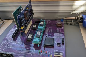
 Dominic Emond-Belanger
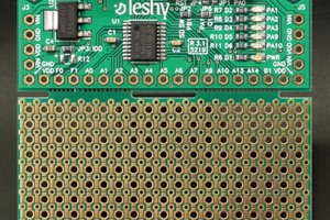
 fruchti