Close
0%
0%

Crestron TSW-732 Teardown

An inside look at the conference room display and touch panel.

Similar projects worth following
I came into a couple of conference room scheduling displays (Crestron TSW-732) and wanted to see if I could salvage the display and touchscreen. Touchscreen is YES, display is NO. Details inside. I conclude its cheaper and less hassle to buy a touchpanel than bother with salvaging one of these. Hmmm.. may be rethinking that if the ESP32-S3 RGB LCD peripheral can drive this. Stay tuned.

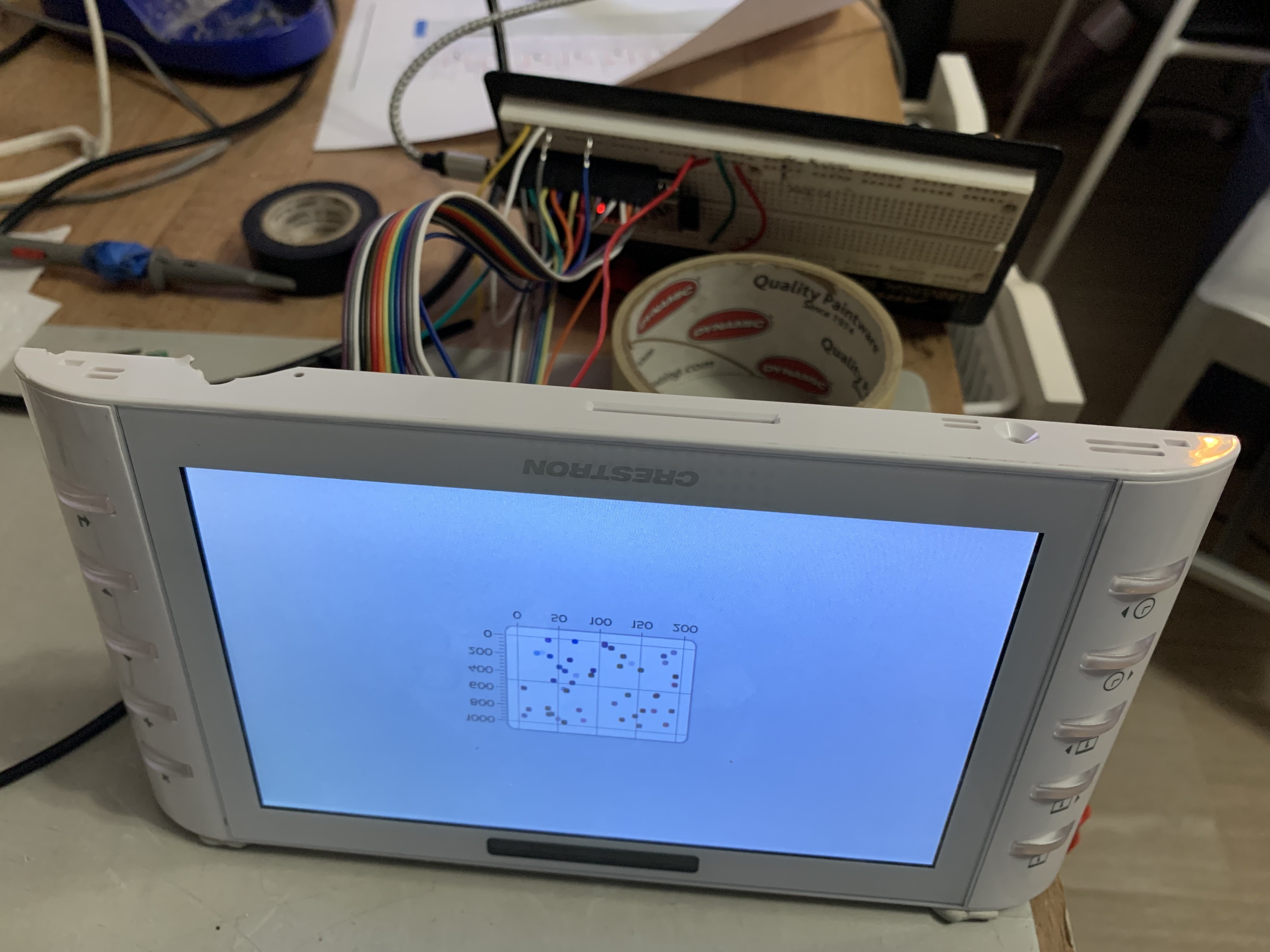
I purchased two of these Crestron TSW-732 units to determine if I could reuse these panels for an educational touchpad “PyPad” running CircuitPython. The Touchscreen can be reused, but unfortunately the display cannot be used easily. Details below.


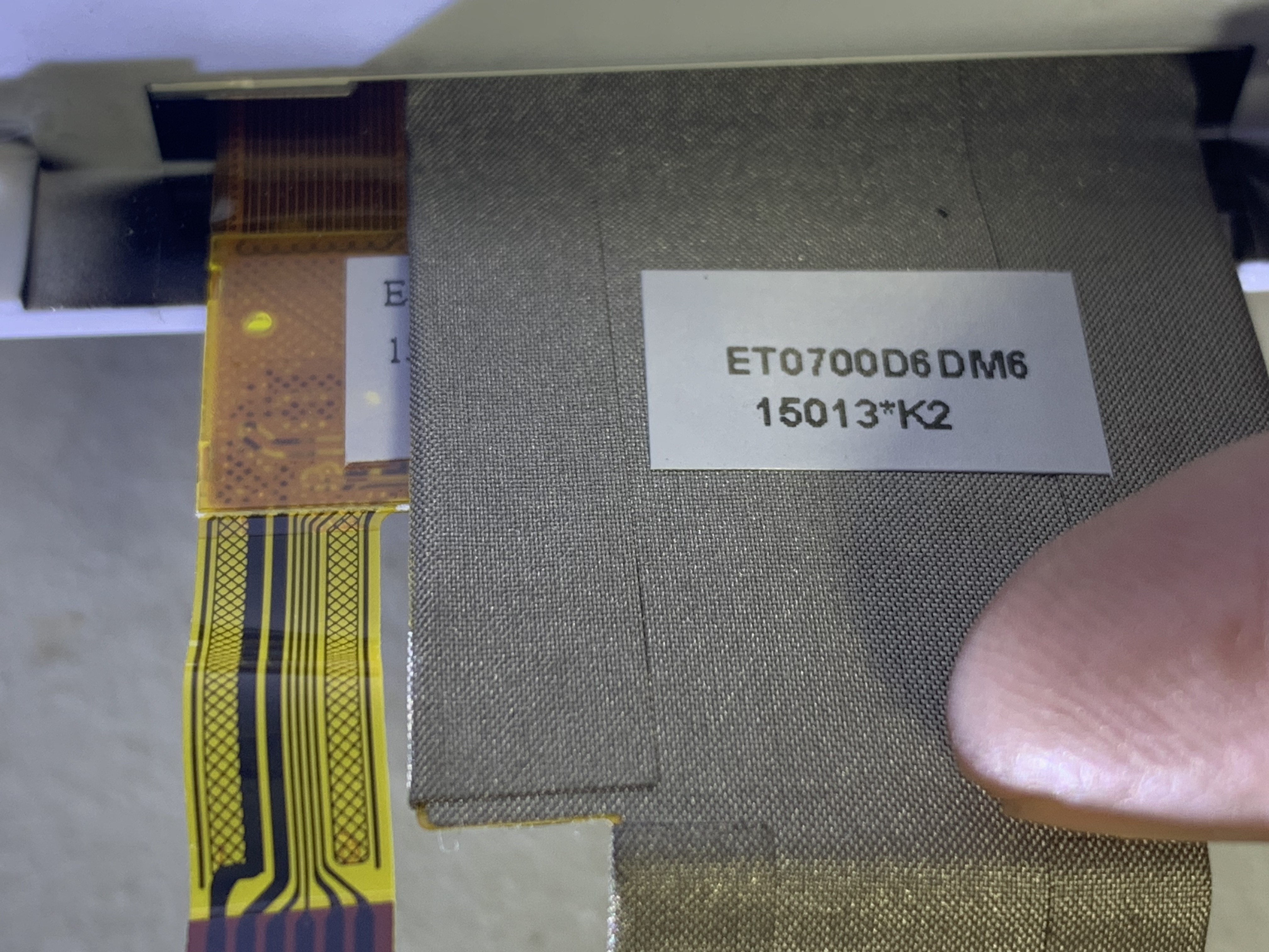
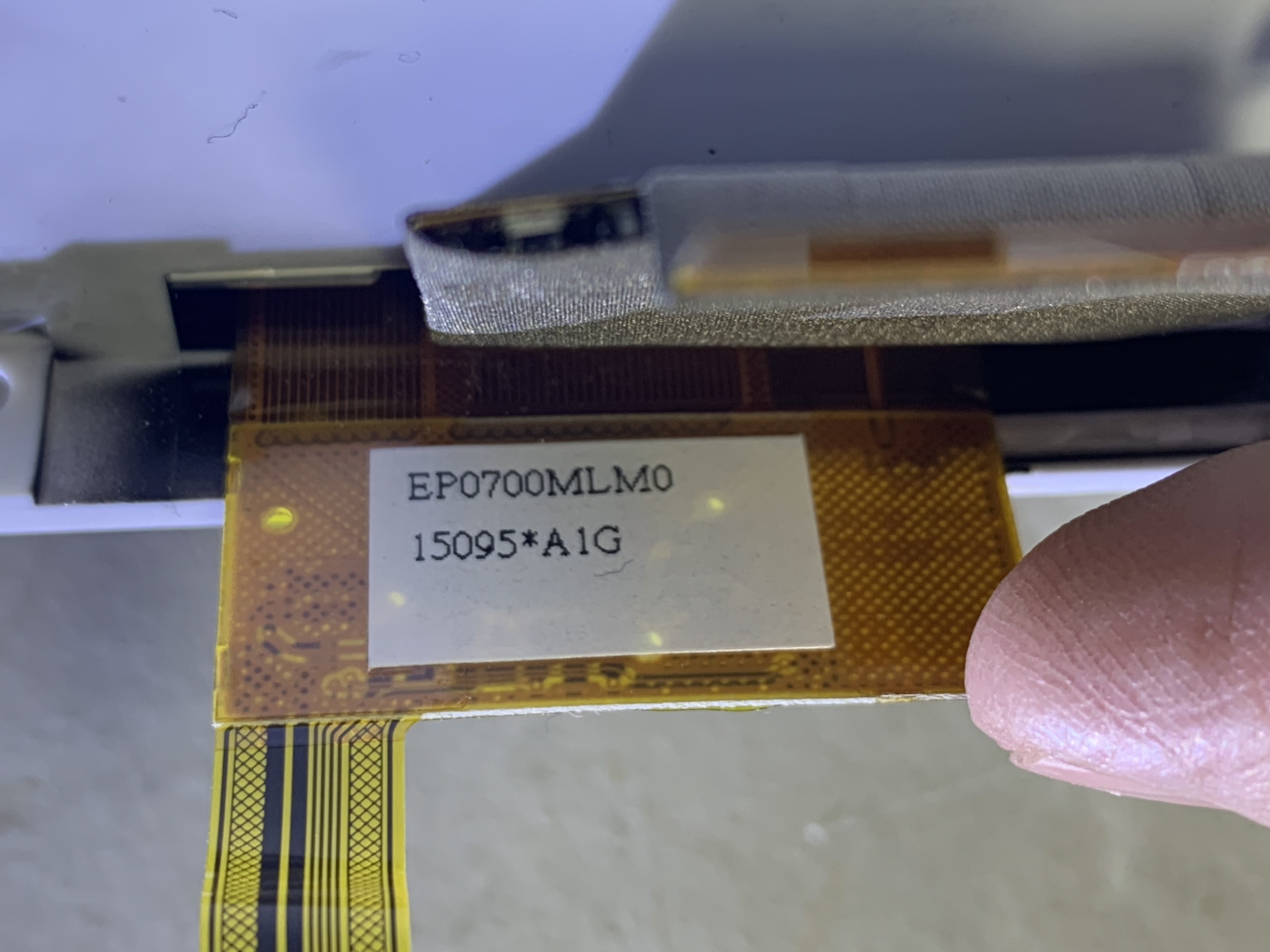
The touchscreen is made by Emerging Display Technologies EDT. The closest part number and pinout looks to be ET070001DM6, datasheet provided in the files section. 

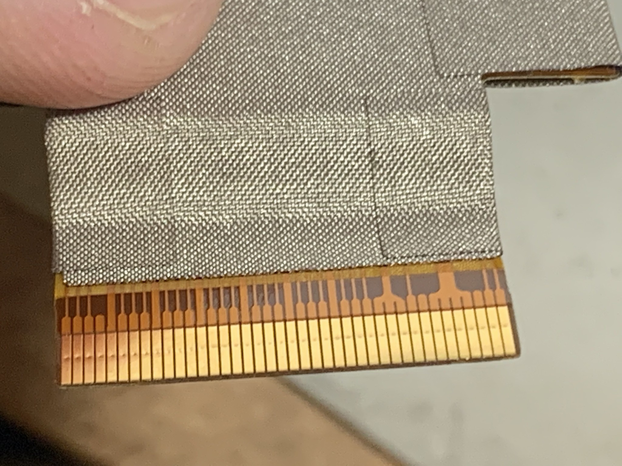
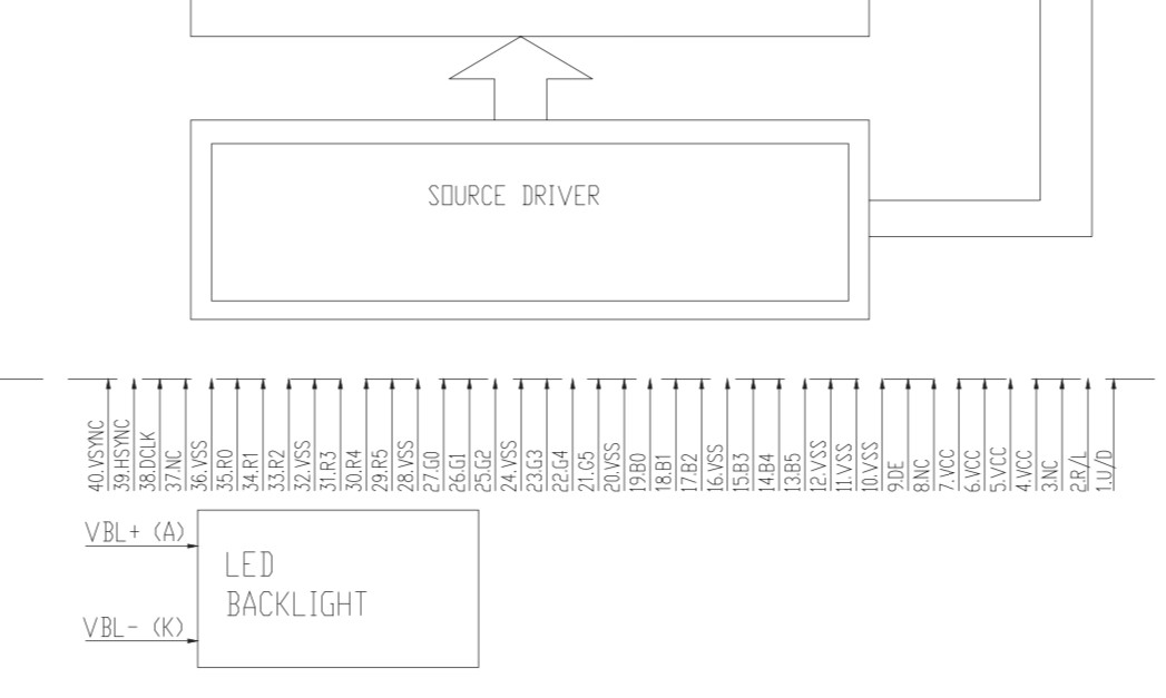
This display does not have a smart controller, it requires a parallel connection and a dot clock. So, you’ll need to add a controller if you want to reuse the 7 inch display. Without a smart display controller, it is difficult to reuse this display.

The touchscreen is however reusable. The 7-inch capacitive touch panel uses a Focal Tech FT5406 connected via I2C with six wires. 

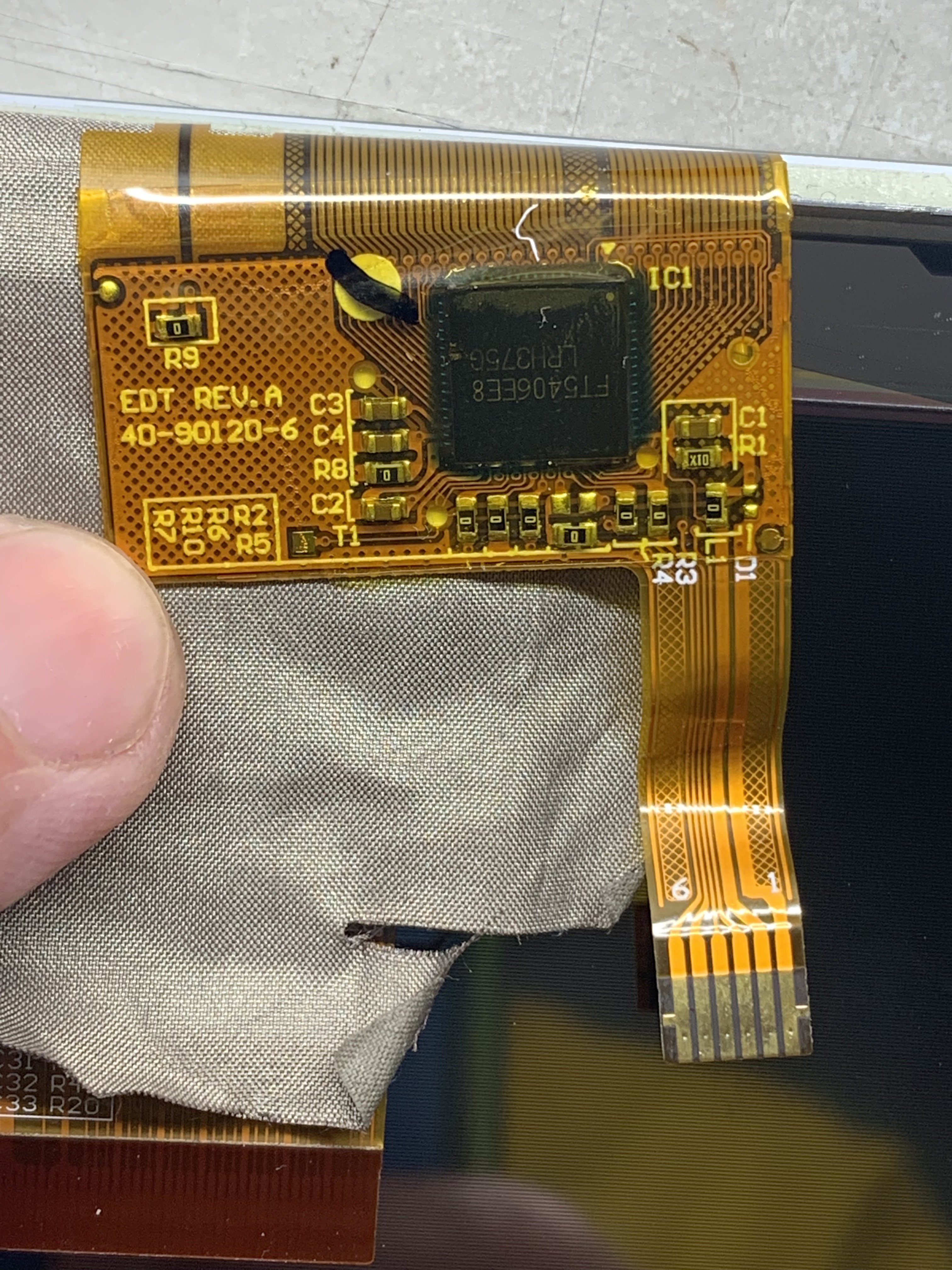
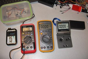
Pinouts are 1: Gnd, 2: 3.3V, 3: SDA, 4: SCL, 5: interrupt and 6: maybe wake but I have not verified. The display is recognized as I2C address 0x38, and a quick arduino sketch using the Sparkfun Arduino library verifies the multitouch capability. 

Other items of note:

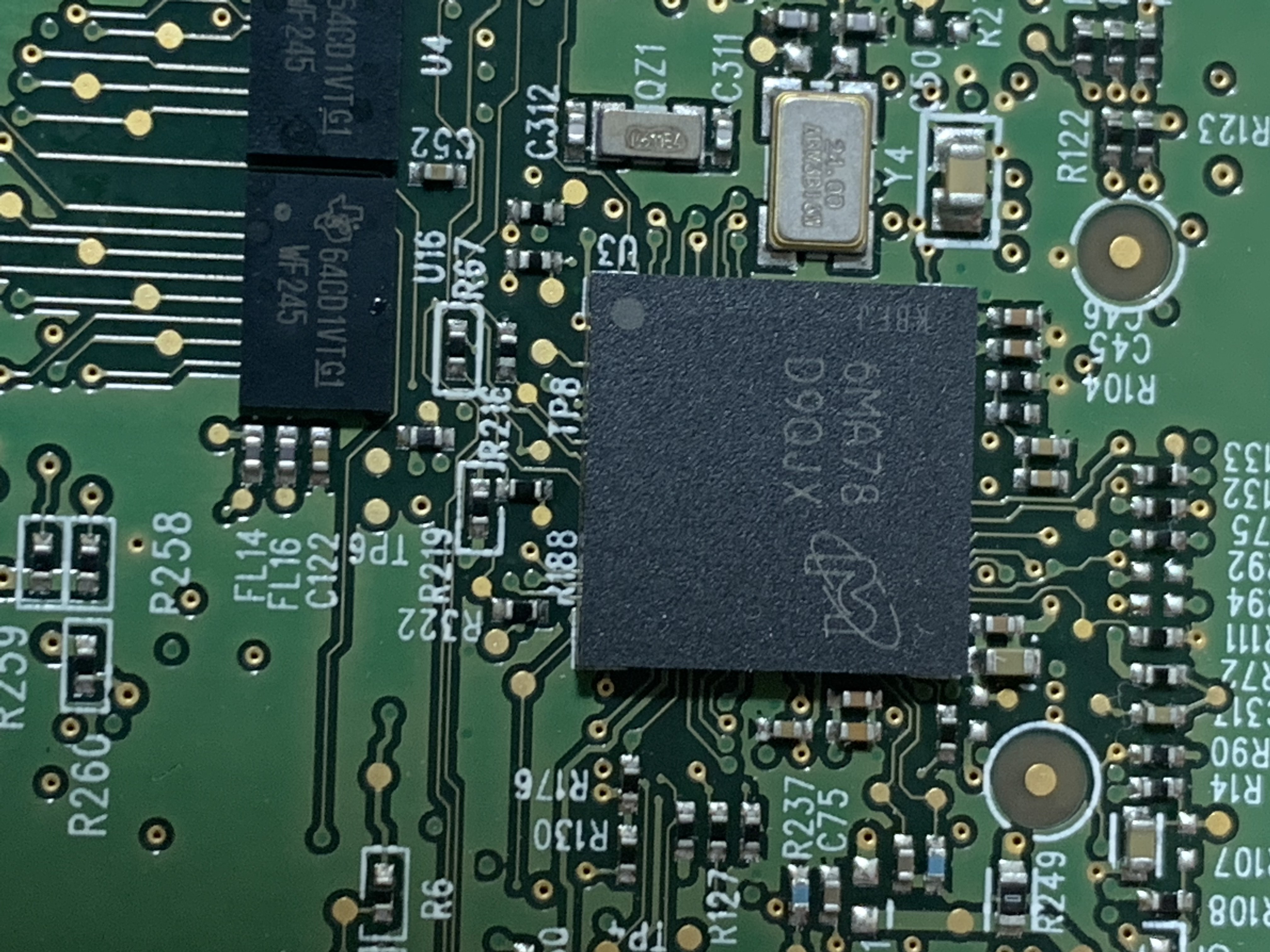
I don’t see a serious microcontroller on this board, but I see a DRAM chip near the display (Micron 6MA78). I surmise that this is a relatively dumb terminal and the display data is pushed to it over the Ethernet connection. 

There is a Flash drive on board that is unreadable on my Mac. Perhaps this is some boot code?

The unit has an amplifier and two speakers, also it seems to have some motion sensing capability, perhaps to wake up when someone arrives at the terminal or to detect if someone is in the room.  There are some connections in the back for room sensors, presumably to see if the room meeting occupants really showed up or whether the room is available. 

Adobe Portable Document Format - 3.78 MB - 02/06/2022 at 02:31

Preview
Download

Adobe Portable Document Format - 1.26 MB - 02/06/2022 at 02:30

Preview
Download

Adobe Portable Document Format - 4.43 MB - 02/06/2022 at 02:30

Preview
Download

JPEG Image - 2.21 MB - 02/06/2022 at 02:22

Preview
Download

JPEG Image - 1.89 MB - 02/06/2022 at 02:22

Preview
Download

View all 35 files

  • Blink!

    kmatch9802/17/2022 at 14:15 0 comments

    I read that the ESP32-S3 has a built in peripheral for driving bare RGB dot clock displays such as the one in my scavenged display. I pulled the display pinout from the data sheet I luckily found on panelook.com for this display connections. Looking at the ribbon cable it looked like a reasonable match (VCC pins were visibly connected, grounds were wider traces than the signal pins).


    After a mad mess of wiring, I compiled and flashes the Espressif RGB LCD demo onto an N8R8 demo board.

    I powered the backlight with a separate power supply and it is alive!

    I have the up/down and left/right pins connected to ground.  Looks like I need to swap the to high. But at minimum it looks like it might work.  Now I need to get this board in a stable state so I’m not fighting the wiring while developing.  

    It runs ok at 10 MHz but an attempt at 30 MHz was glitchy. I think the long wiring may be a limiting factor right now, but it’s good enough for initial code development. 

View project log

Enjoy this project?

Share

Discussions

Similar Projects

Does this project spark your interest?

Become a member to follow this project and never miss any updates