 Pixelbo
Hello!
My vacation is now over, I had a little tchat with my teacher and we figured out that the most "easy" way to have multiple cameras without denuding the already present wires is to have:
-A pair of wires with RS485 bidirectional
First of all we need to configure the camera via the dip switch, we have 3 possible modes:
(TX is here from Arduino to camera and RX camera to Arduino)
-RS422 with 5 wires (GND, TX-, TX+ and RX- ,RX+)
-RS485 with 4 wires (TX-, TX+ and RX- ,RX+)
-RS485 with 2 wires (TX-, TX+ OR TX-, TX+ and RX- ,RX+)
Of course we want RS485 with 2 wires, however we encountered a problem: the TX module was supplying 5v (in idle state) to the camera even when it responded (For more explanation).
The solution to this problem: control the TX module's idle voltage with pinout!
I use an esp32, so the pins delivers 3v3 but that's not a problem because the chip function fine with 3v3 and the camera still works (The voltage differential is enough big)
So I grabbed my jumper wires and a schematic like this:
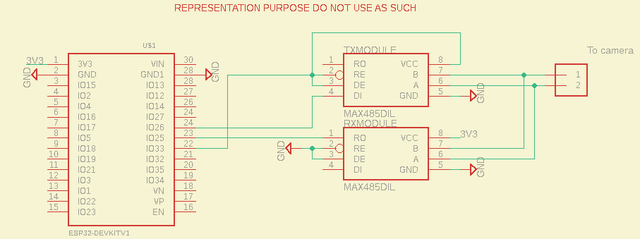
You can see that the TX module's Read Enable, Driver EN and vcc is controlled by tht IO33.
This module pins work like this
| VCC | RE pin | DE pin | Module state |
|---|---|---|---|
| 3V3 | LOW | LOW | Receiver |
| 3V3 | HIGH | HIGH | Transceiver |
| 0V | HIGH | HIGH | Residual voltage |
| 0V | LOW | LOW | Nothing |
but what is the is the result, here are the result in UART communication from RX module to Arduino:
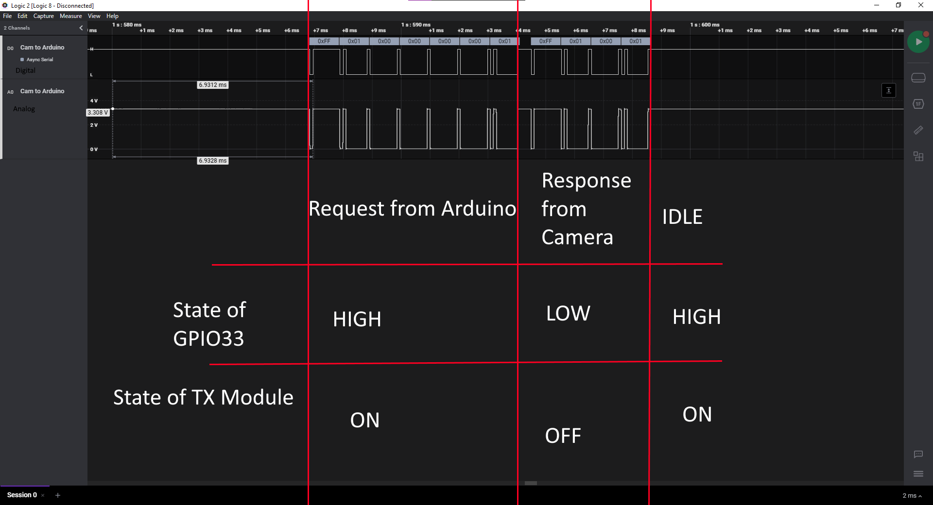
Still "One problem": we detect also the TX module transmission but that's not a problem because we can filter it out in the software:
Well that was all for today, see you next for Software Improvements!
Bonus: the code is now looking like this (tempory code):
#include "Arduino.h"
#include <Pelco_And_Arduino.h>
/////////////////Address,baud,tx  ,rx , logging

PelcoCam PelcoCam(0x01, 9600, 25, 26, true);

int testpin = 33;

void setup() {

  init_OTA();
  pinMode(25, OUTPUT);
  pinMode(26, INPUT);
  PelcoCam.begin();

  PelcoCam.send_command(STOP);
  pinMode(testpin, OUTPUT);
  digitalWrite(testpin, HIGH);
  Serial.println("Init Finished!");
}


void loop() {

  PelcoCam.send_command(STOP);
  delay(1000);
  PelcoCam.send_request(QUERY_PAN);
  digitalWrite(testpin, LOW);
  delay(500);
  digitalWrite(testpin, HIGH);
  delay(500);
}
Discussions
Become a Hackaday.io Member
Create an account to leave a comment. Already have an account? Log In.
Thanks, I did it! https://wokwi.com/projects/392057678139446273
Are you sure? yes | no
Amazing job!
Are you sure? yes | no
Any idea about how to simulate your peoject in WOKWI? https://wokwi.com/projects/377014769065300993
Are you sure? yes | no
I think if you can decode the whole message from the arduino and then send back an Acknowledge message back to the arduino it could be done. Messages follow a data frame and shouldn't be too hard to decode.
I could help you on that if you want, however I'm studying and have exams in the next weeks.
Are you sure? yes | no