 Pixelbo
Hello and welcome back to a project log!
I would first thank you all for following me in this project and huge thanks to Arsenijs Picugins who made an article about RS485 which is very well documented
Ok so what's new?
Well there is 3 chapters:
- 6 hours of debugging can save you 5 minutes of reading documentation
- The camera, the keypad and the computer
- Arduino administration is simpler than France one
6 hours of debugging can save you 5 minutes of reading documentation
Ok so to resume, the lib need to know which command we are sending to correctly parse the input data (e.g: if the command is SET_PAN , the lib must compute the given angle to hex values to transmit)
The solution: have a list with every special case!
const byte CMND1[5] PROGMEM = {FOCUS_N, IRIS_O, IRIS_C, OFF, ON}; //List of all commands that go on the byte3; a list with command 2 is not required, a bit of logic please
const byte DATA1[2] PROGMEM = {PAN_L, PAN_R}; //List of all commands that use ONLY the DATA1 for data pass

const byte SETPOS[3] PROGMEM = {SET_PAN, SET_TILT, SET_ZOOM}; //List of all command that require an MSB and LSB

const byte DATA_BOTH[5] PROGMEM= {PAN_L_TILT_D, PAN_L_TILT_U, PAN_R_TILT_D, PAN_R_TILT_U, WRITE_CHAR};//List of all commands that use the DATA1 and DATA2 for data pass (excluding the SETPOS' commands)

const byte RESP_CMND[3] PROGMEM = {RESP_PAN, RESP_TILT, RESP_ZOOM};

const byte QUERY_CMND[3] PROGMEM = {QUERY_PAN, QUERY_TILT, QUERY_ZOOM};

const byte PRESET_CMND[3] PROGMEM= {SET_PRESET, CLR_PRESET, GOTO_PRESET}; //will I use it?
The problem: Getting a value of progmem's flash isn't what it is.
If I want to compare the Command PAN_L to DATA1, I can't use a loop with DATA1[i] (with i incrementing)
why? Because progmem is maintained by a library: pgmspace.h (more on the arduino refenrece)
The solution: After reading a bit of documentation, you actually need to do this:
pgm_read_byte(&DATA1[i]) //(Demo purpose not in the lib)
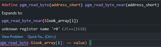 Ok problem fixed
The camera, the keypad and the computer
I swear the title is not a Clint Eastwood reference O_O
What do we do with a functionning library, we test it!
I had keypad laying around my place so I plugged him in the esp and onto the testing and good news!
The 2 modules that generates RS485 works with the 2 mains architectures (avr and esp32)
Ok little demo video right there /\
Arduino administration is simpler than France one
With the library completed ( I strongly suggest you to see the github repo, there are new examples, etc)
I updated the library.properties and the created keywords to create style coloring:

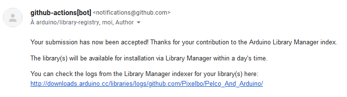
So with this and that next step, uploading it to the arduino library manager (again thx because the documentation is really great)
A few hour later:
Well now you can download it from the library manager ! (it's so coool)
Well with this project log finished, until next time!!!
Discussions
Become a Hackaday.io Member
Create an account to leave a comment. Already have an account? Log In.
Can you please explain how to use the RE pin and which module to use? And how do I determine the address of my camera?
Are you sure? yes | no
Hello there !
I've used a MAX485 to communicate with the camera. The RE pin (and the DE pin) stands for Receiver Enable and Drive Enable. The RE pin is logically inverted so when RE and DE are Low, the module switches to Receiver mode and when they are set to High, it switches to Transceiver mode. This switch is taken care of in the library, you just have to wire the RE and DE pin to an Arduino pin. I've explained this further in this log:
https://hackaday.io/project/183986-controlling-a-cctv-camera-with-arduino/log/203634-the-return-of-the-camera
If you want to get fancy, you could use a MAX13487E which switches automatically between RX and TX. See https://hackaday.io/project/183986-controlling-a-cctv-camera-with-arduino/log/203133-the-two-towers
I hope I answered your question !
Are you sure? yes | no
Do you mean transceiver (transmitter + receiver) or just transmitter?
And I've seen that page, but schematic says "don't use as such", and sketch uses a different library initialization w.r.t all examples in the repo, so I am not understanding what to do. Should I use PelcoCam PelcoCam(0x01, 9600, 25, 26, true) or PelcoBus MyPelcoBus(6, 7, 8) followed by PelcoCam Camera1(&MyPelcoBus, 1, false) ?
Are you sure? yes | no
Indeed I was wrong, it is not transceiver and well transmitter, sorry for the misunderstanding.
The schematics says "don't use as such" because it uses two MAX485 modules and it isn't recommended. It is more simpler to use one module with the RE and DE pins hooked up to the mcu.
The exemple in the log is old and shouldn't be used. The exemple in the repo should work fine. So yeah, PelcoBus MyPelcoBus(6, 7, 8) followed by PelcoCam Camera1(&MyPelcoBus, 1, false)
Are you sure? yes | no