 ric866
First and foremost... I am not responsible for you destroying your Pet Sure Cat Flap, any other incidents that may occur in your home, the death of your PC, or any nuclear war that might result from you attempting to build any part of this project. With that out the way, if you do decide to experiment with your cat flap, they are quite robust (they can accommodate batteries being put in the wrong way around), but I recommend doing some basic volt meter diligence before connecting anything to the cat flap.
This Project had a few simple objectives :
- Reduce the amount of time I spend changing and charging rechargeable AA batteries
- Reduce the amount of battery waste my cat flap is producing (if I don't use rechargeable batteries)
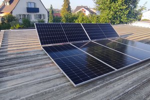
- Make use of the UPS fed 12v supply installed to power the previous RFID cat flap
- Give me a good reason to spend days messing around with the 3d printer
With that came a few constraints :
- Retain the appearance and original structure of the cat flap - no cutting of any original parts. It was after all expensive, has a warranty, and if it has a defect I might still want to return it.
- No / minimal reduction in RFID sensitivity & range (PetSure cite this as the reason battery eliminators are not suitable for their cat flaps)
- Have an inbuilt battery backup of some kind, to cope with a power outage after the AC powered UPS runs out of charge.
- Use modular, easy to source parts, that are easy to put together.
- Have a case that can be easily 3d printed, attach securely (in that it doesn't fall off), be reasonably dirt resistant , and be aesthetically acceptable.
Then on to the design and build:
I will split this bit into two parts, electrical, and enclosure, but I am writing from my head to the page, so reserve the right to go off piste.
The Enclosure (not the electrical part)
After measuring the original battery cover very carefully, and drawing it out (it's curved in some interesting ways) designing the new lid with some storage and supports in it seemed like it should be quite easy.... And so I continued to think until I attempted to print the unit, which came out OK, but needed more material in the supports than in the product.
So a couple of iterations later, I split the base, the main compartment and the lid, to allow for easy re-printing of the main compartment to get the containment for the modules and fittings just right.
Bit more measuring and some well placed access holes (the cable feed hole into the battery bay lines up with the terminal posts on the cat flap, so you can stick little spade connectors behind the terminals when you get fed up with the quality of those battery eliminators).
As a sideline, I drew up a lid that integrated an additional AA battery... This should mean if you want to continue with rechargeable batteries, the power level will be around 6v instead of at around 4.8v when using 1.2v cells. It will need some crimp on terminals (like you find on cars and motorcycles, but flat) which should poke through the little holes in the print, intercepting the rearmost (away from the door side) batteries.
The Electrical
Prior to the design work on the enclosure getting too far down the road, I knew I needed something to take 12v down to 6v, be very smooth on its output, and have enough power to drive the little solenoid, the zigbee, and the RFID in the catflap. (I think Petsure have some fairly big capacitors in there anyway).
After hours scouring the internet looking a little DC-DC Buck converters, I knew what I needed should be isolated to prevent transients and noise, but also wanted to be cheap.
My problem being isolated supplies are expensive, just provide stable regulated output (no voltage reduction) or are of dubious quality. While Buck converters are cheap, provide a nice adjustable voltage, they make horrible things happen...
Read more »
 Dominic Buchstaller
 tiefpunkt
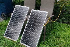
 Drew Pilcher
 Bryan Williams
Hi ric866, So great project ! I have to inform you that I have adapted your project to my needs and also made it French. I included a link to your project in my tutorial. See it here : https://fr.ifixit.com/Tutoriel/Remplacement+pile+par+branchement+secteur/171299