Zach Armstrong
Preface: PCBs and parts
While building a Tesla coil on a breadboard is possible, you may find it frustrating and more prone to issues. For these reasons, I designed a custom PCB for this circuit which can be downloaded here: https://drive.google.com/file/d/11MJa5GTr7-2HdkTSjfyX_S2E6avNrjo8/view?usp=sharing
This .zip file should contain everything from PCB gerber files to a full set of instructions with a parts list (complete with links)! Be sure to check it out, the download is totally free, so you have nothing to lose!
How it works
The circuit accepts a feedback signal either from antenna feedback or from a feedback winding (“ANT.” and “FEED.” on the PCB, use whichever method you prefer. I recommend antenna feedback for beginners). This signal is then filtered, limited, and cleaned up by a resistor, capacitor, and diode clipping array. After this, the signal passes through a 74HC14 Schmitt trigger, which converts the somewhat sloppy signal into a more functional squarewave that matches the resonant frequency. This squarewave signal is then sent to a pair of UCC gate driver ICs (one UCC37322 and one UCC37321), which amplify the signal. These gate driver chip feature enable pins, which basically act like the on-and-off switch. If we feed the interrupter’s signal to the enable pins, we can control the Tesla coil’s pulse width and frequency (BPS).
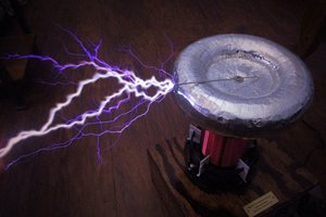
The resulting interrupted signal from our gate driver ICs is finally sent to a small device known as a gate drive transformer, or GDT. If properly assembled, the GDT converts the single 12V signal from our driver into two 18 volts signals, which are perfect for switching our transistors. By phasing the GDT correctly, the transistors will switch the DC voltage from our power supply across the primary coil at the resonant frequency. This causes a massive voltage to be induced in the larger secondary coil, which causes the beautiful display of homebrew lightning that all Tesla coil fans know and love.
Dual resonance and the flip-flop
Up until this point, I’ve basically described the construction of a classic SSTC. So, what sets this build apart as a DRSSTC? There are actually a few things: first, the resonant capacitor. The main drawback of solid-state Tesla coils like the LabCoatz SSTC 2.0 is that their current is limited by the primary circuit. The primary coil has a certain inductance, and that inductance causes a kind of resistance specific to AC signals, known as reactance. Fortunately, there is a trick to eliminate this unwanted reactance, and that is to add a capacitor of a specific size in series with the inductor. If the capacitor-inductor combination has a resonant frequency matching the frequency being applied to it, the reactances cancel, leaving only the very small resistance of the wire itself. This is, in fact, the main principle behind dual resonance: the goal is to have the primary circuit tuned so that its reactance is near zero, which allows the resonant signal produced by the solid state circuitry to flow unimpeded at very high currents. Higher primary currents result in higher secondary voltages, and therefore longer sparks.
Unfortunately, making a DRSSTC isn’t as simple as throwing a resonant-size capacitor into any old SSTC. If you saw the tutorial for the LabCoatz SSTC 2.0, you might remember that I had to avoid primary impedances below 6 ohms to keep the IGBTs alive. So how do DRSSTCs get away with nearly zero ohms of impedance? As it turns out, the secret is in the switching: for a DRSSTC to function properly without failing, it is necessary to soft-switch the transistors. This is where the flip-flop comes into play: essentially, it prevents the interrupter from shutting off your transistors while current is flowing, which could kill them if you’re running in dual resonance.
For best results with a flip-flop, primary feedback is recommended over secondary or antenna feedback. If you choose to use primary...
Read more »
 Yann Guidon / YGDES