Okiday, Futaba 20-SD-06GK VFD on the workbench with the filament heated. Fiftynine pins and no datasheet. The two outermost pins on each side were for the filament. The tube has 20 grid segments (one for each character) and 35 anode segments (5x7 phosphor pixels). So of the remaining 55 pins 20 should be for grid biasing and 35 for anode segments.
My standard protocol for VFD pin probing is to use a small (1.3 Ah) lead-acid 12 V battery. Connect the negative terminal to the filament ground pin and connect two alligator leads to the battery positive terminal. If one alligator clip touches a grid pin and the other touches an anode pin, the phosphor on the anode segment should light up faintly. VFDs are made to operate with very positive grid bias, often with Vgk=Vak ≈ 20 V, so 12 V should be close enough. A higher voltage would be less forgiving if you accidentally touch the filament pin.
However, in the photo below the grid pin (g15) is connected to positive filament voltage (3.1 V) and the anode pin (a1,2) is connected to a power supply.
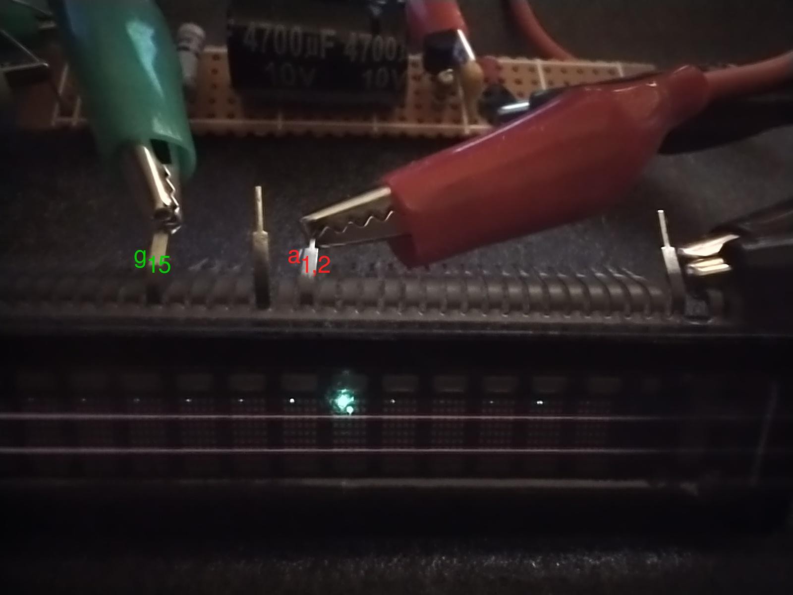
The voltage on the surrounding grid pins is floating, and apparently high enough to let some electrons through. The filament wires look light gray in this photo, but were dull orange to the naked eye.
The intended use is to multiplex the shared anode segments by pulling one grid pin high at a time and to loop though grids 1 through 20 fast enough that persistence of vision makes it look like all 20 characters are continuously lit.
For the Futaba 20-SD-06GK VFD, from left to right, pins 3-17 are a5,1 to a7,5 (row major), pins 18-37 are g1 to g20, and pins 38-57 are a1,1 to a4,5.
The low-voltage probing (at 12 V) works well enough for me to use it even when I do have a datasheet for a VFD.
Discussions
Become a Hackaday.io Member
Create an account to leave a comment. Already have an account? Log In.