I found the pins on the Futaba 20-SD-06GK VFD to only reluctantly accept solder so I ended up using my harshest flux (for stainless steel), and lots of it. I did wash off the flux residue with alcohol, but when I later added the battery holder (for neutralizing the luminance slant), I inadvertently left some flux. With a 140 V potential difference between two adjacent pins (a4,5 and g1), the flux residue became a conductor and the ohmic heating was enough to leave a scorch mark (and release some Magic Smoke):
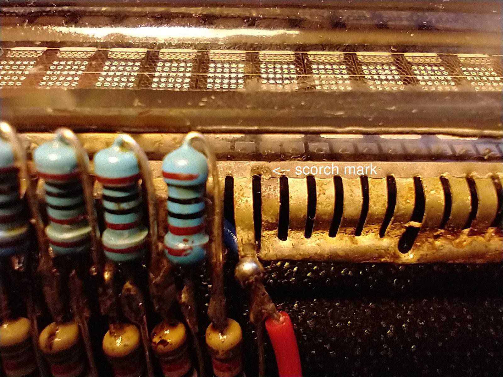
However, after another alcohol wash, the device was functional. The lesson learned is that VFDs are not made for operation at the anode voltages necessary with a negative grid bias, so special precautions need to be taken. Liquid electrical tape where the grid is closest to the anode would probably be a good idea.
I hooked the VFD triode up to two power supplies (one for anode voltage Vak and the other for grid bias Vgk), in addition to the filament PS. Here are the anode currents Ia measured by a multimeter:
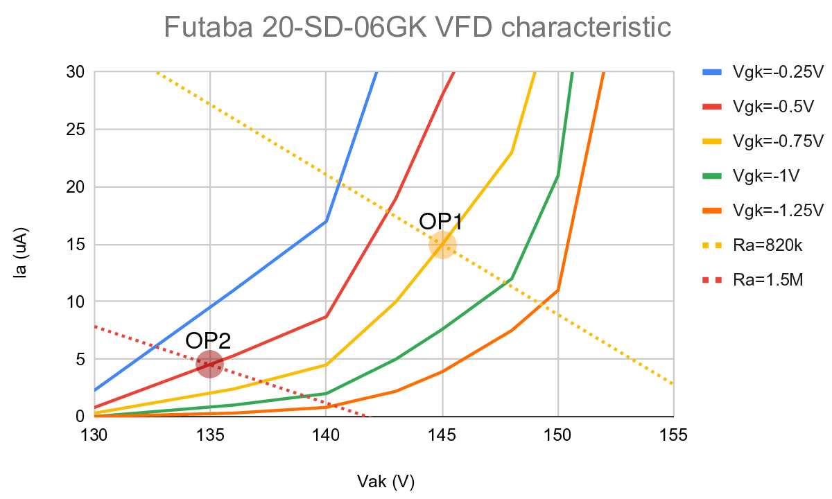
I've identified two possible operating points (OP1 and OP2, respectively). My preferred option would be OP1, which has voltage gain A = 11 (+21dB) and anode resistance ra = 400 kΩ (estimates from eyeballing the characteristic above). As for all VFDs, the output impedance is high, about 270 kΩ. You'll need a PS capable of producing very clean DC at relatively high voltage: B+ = 157 V. The anode dissipation is Pa = 2.2 mW, which would be trivial for a conventional triode, but might be a bit high for a VFD. The fallback operating point OP2 has A = 10 (+20dB), ra= 1400 kΩ (resulting in an output impedance of 720 kΩ), B+ = 142 V and Pa = 0.6 mW.
A surprising (at least to me) and tantalizing fact is that gain around OP1 drops fairly symmetrically for higher and lower grid bias. For a guitar preamp the resulting soft and symmetric clipping is associated with "tubey" guitar tone. You would need the signal to have Vpp close to 1 V for this "euphonic distortion" to kick in though.
The results so far are thus encouraging enough for me to continue my VFD shenanigans: a gain of +20dB seems very achievable, the output impedance is high, but manageable and you might even get some pleasant coloring as an added bonus!
Discussions
Become a Hackaday.io Member
Create an account to leave a comment. Already have an account? Log In.