 kelvinA
So I'm considering a 125mm solar cell for Tetent, and since this is much longer than my initial assumtion of a 75mm Tetrinsic, I thought I'd actually get a simulation.
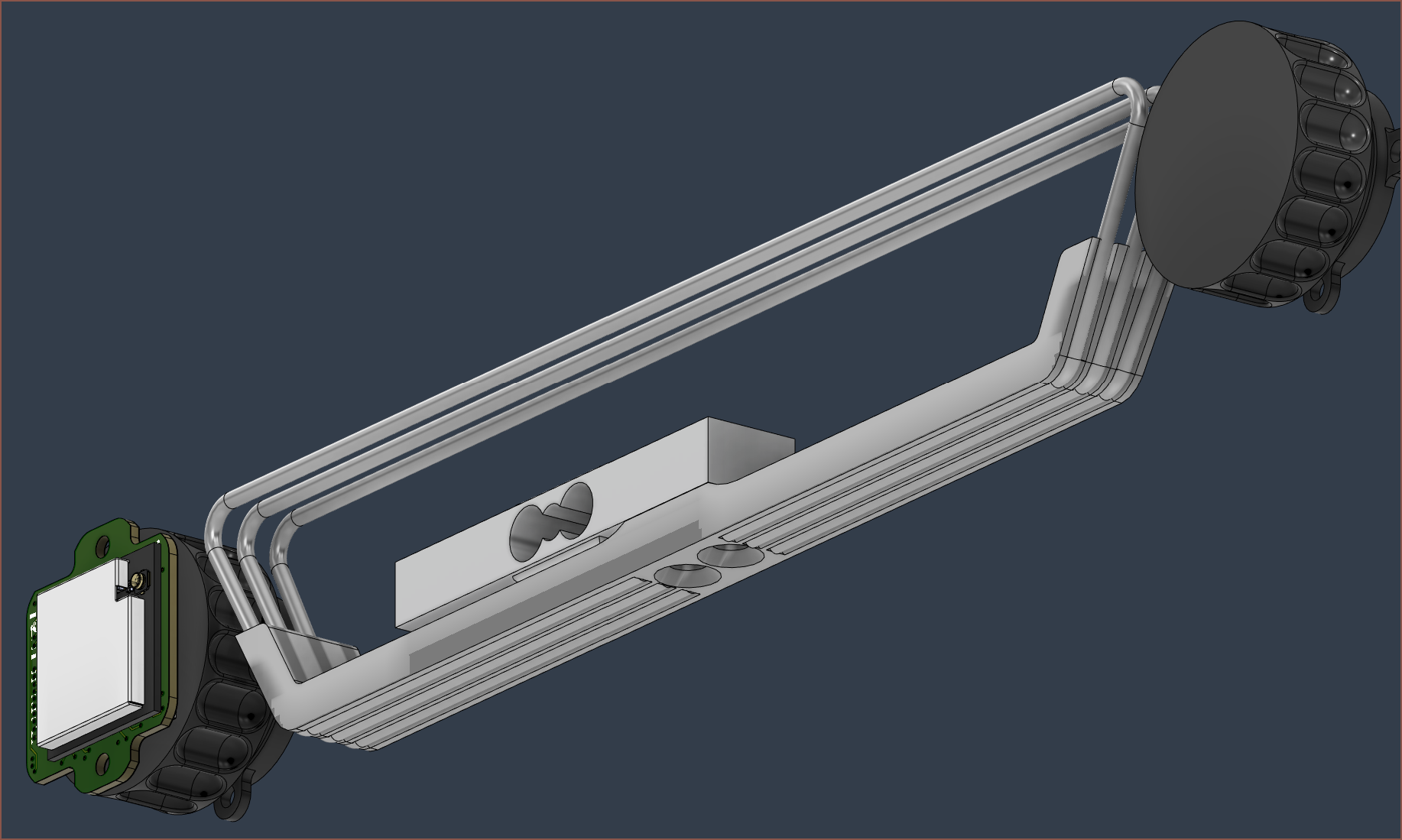
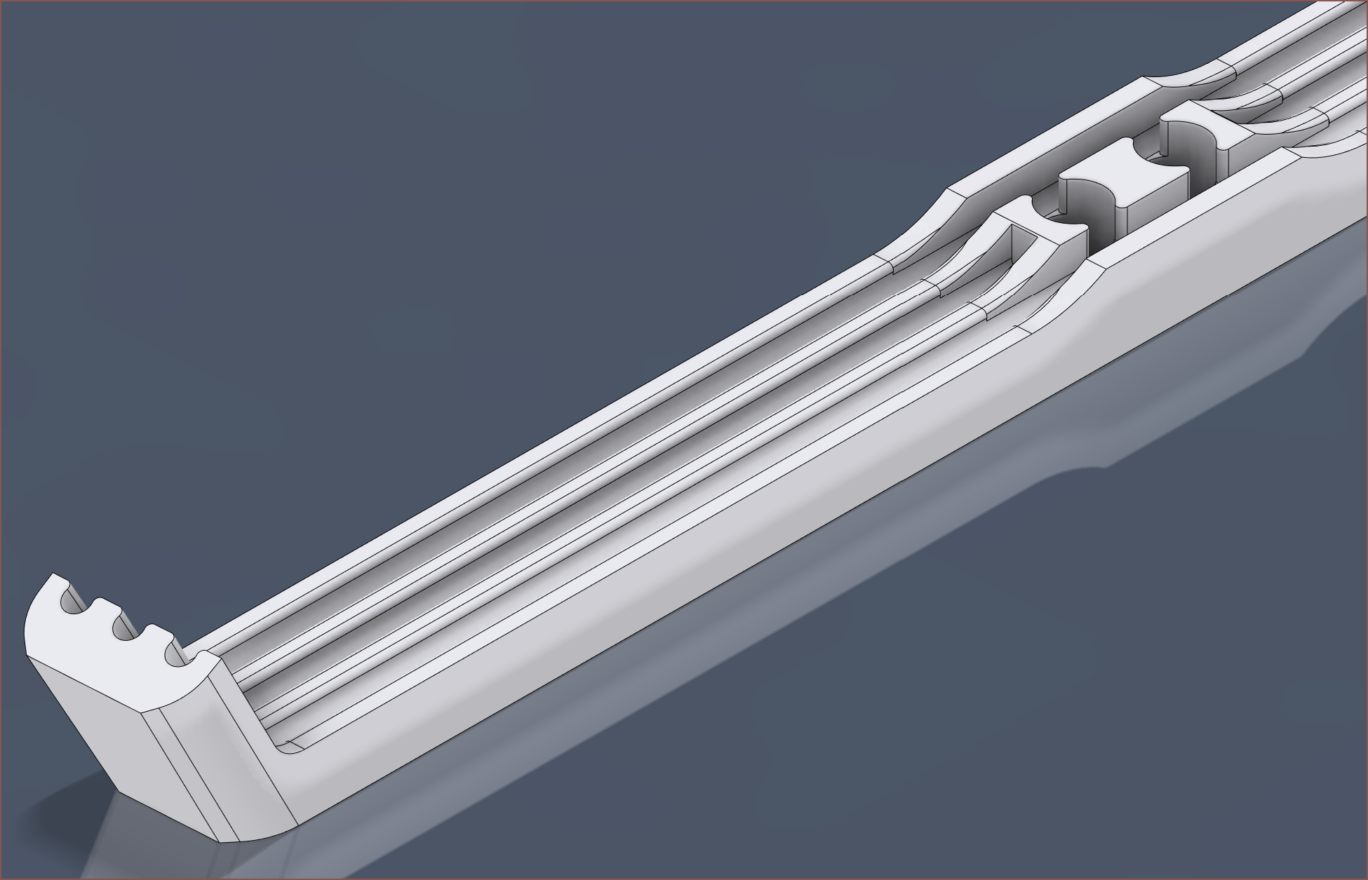
I've modelled the tubes with a 60 degree inwards bend (instead of a 90 degree straight-down bend) so that the ball chain can take a shallower angle from the sprocket to the sides of the "pressure collector" as I call it.
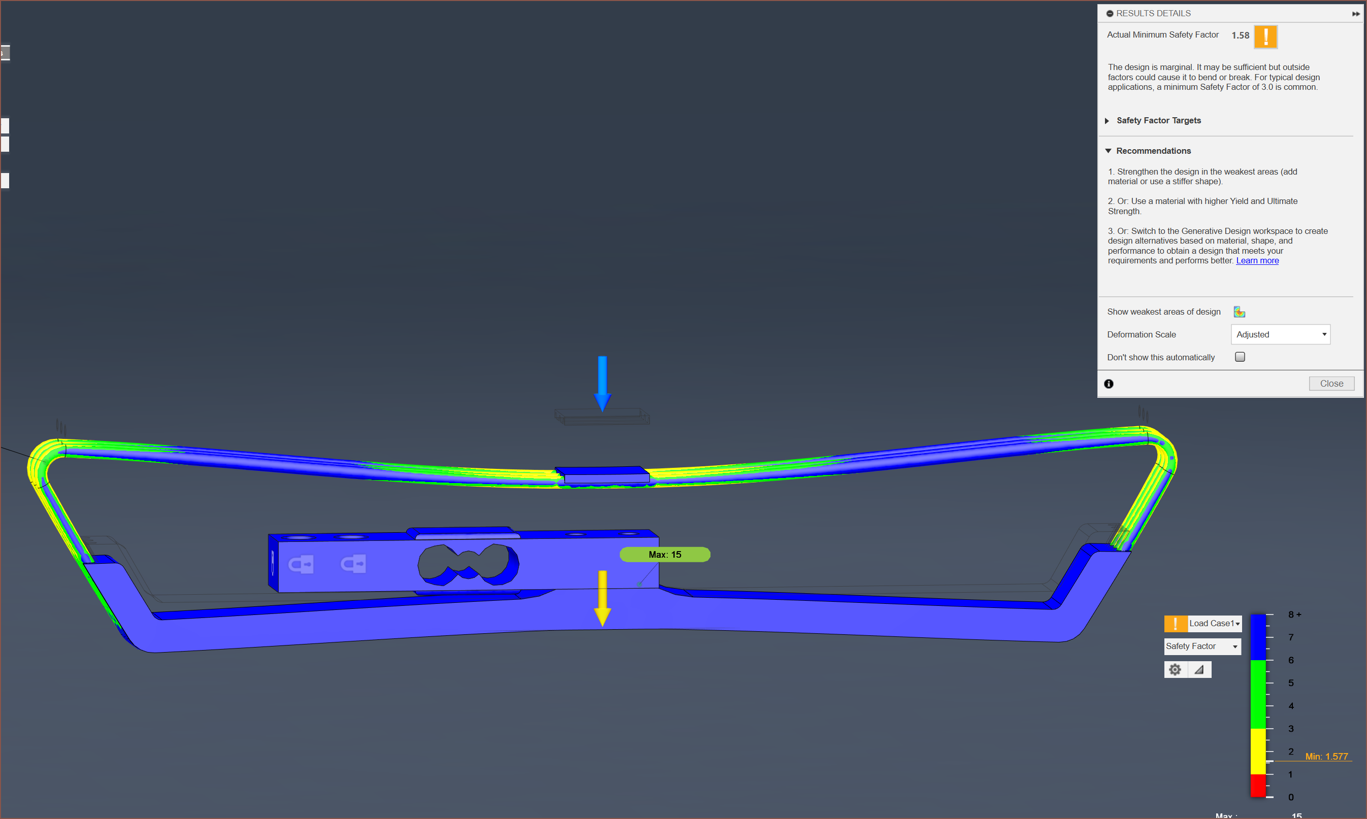
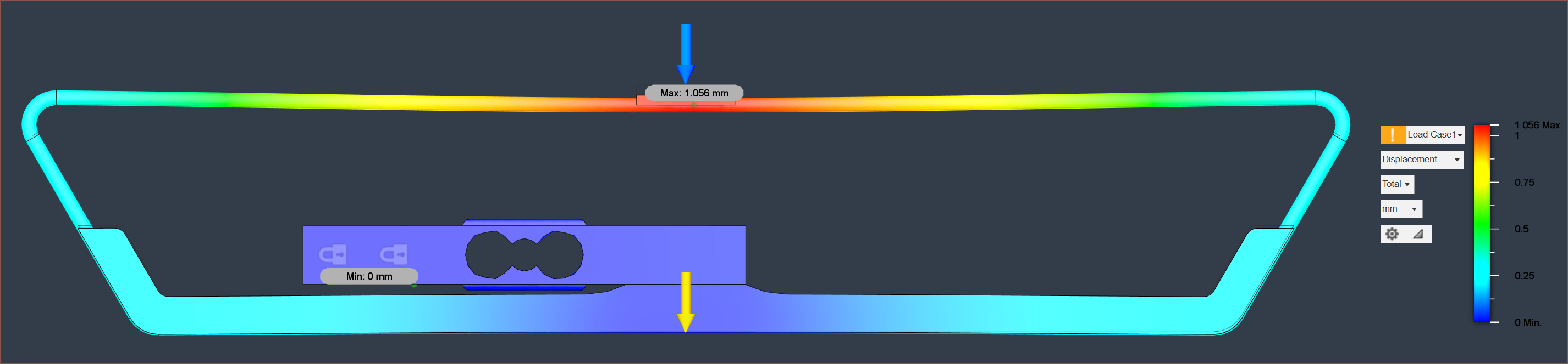
I've got a 500gf load exerted from the middle of the area, and it's already not looking so good, acheiving a minimum safety factor under 2. The good news is that, as expected, the load cell has almost no displacement, meaning that the force sensing area is symmetrical when under load.
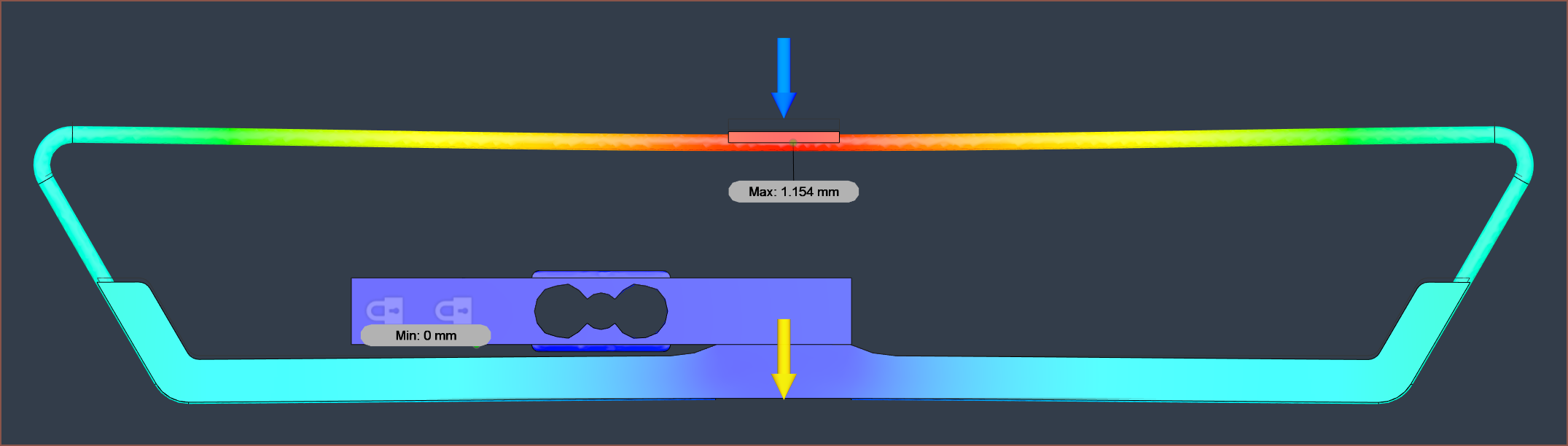
The displacement is rather high, at 1.15mm. My goal is to cut that in half somehow.
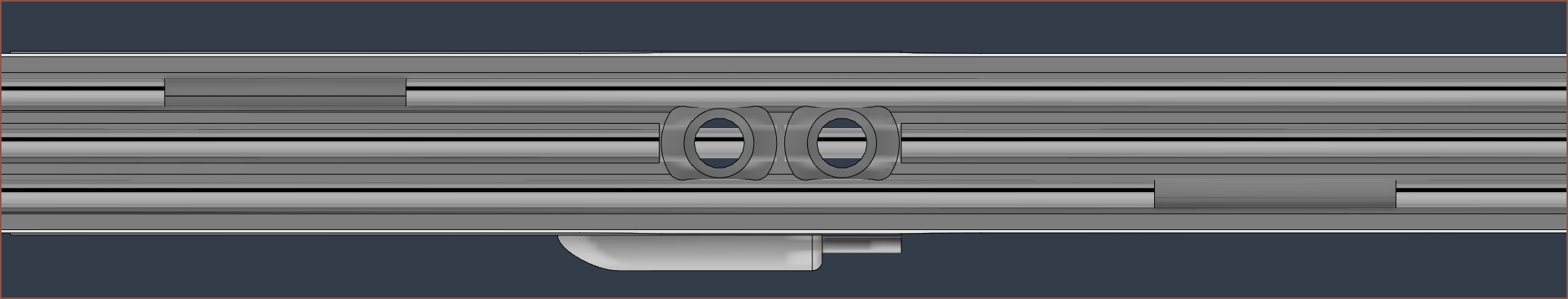
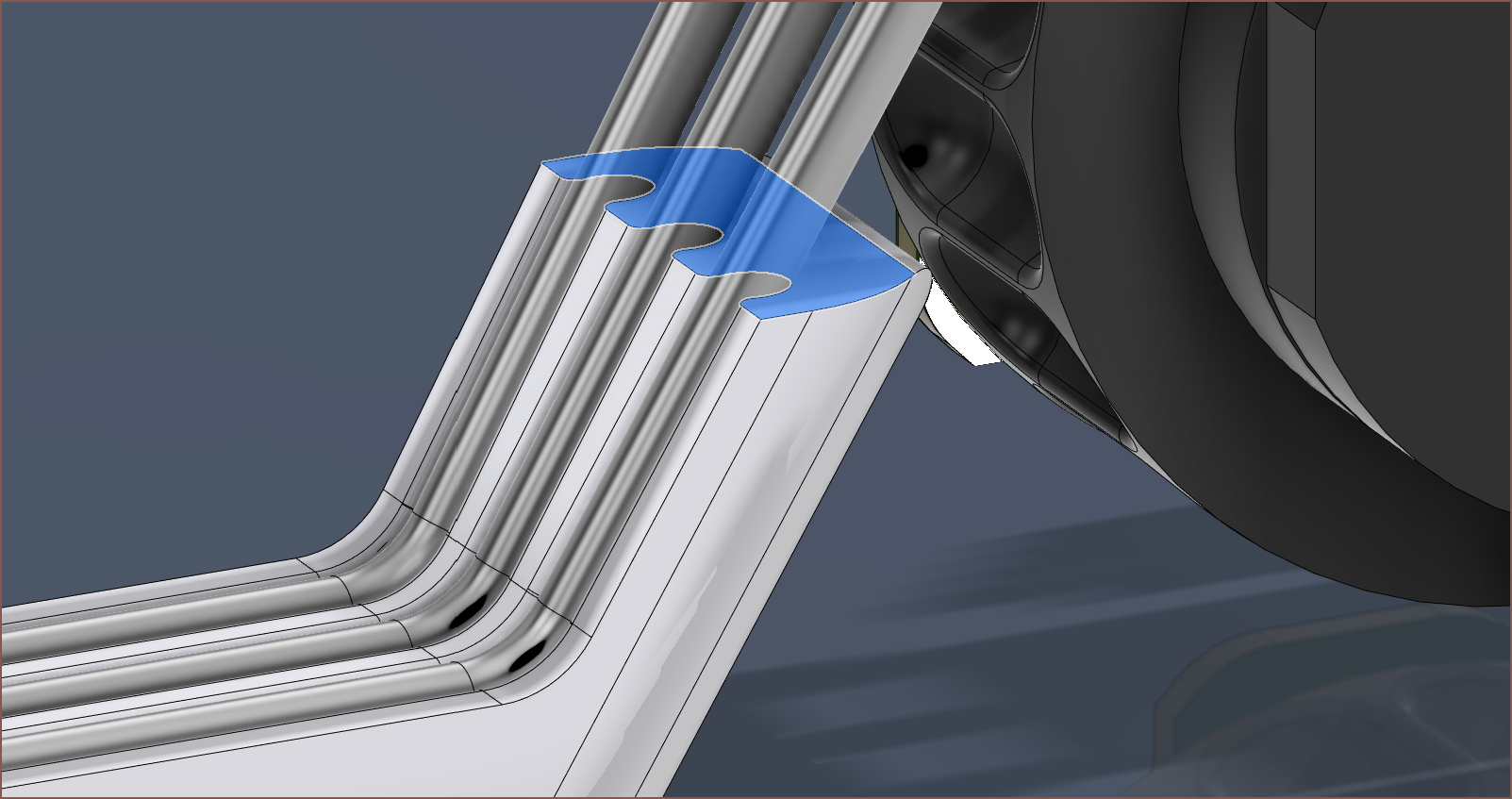
This is where the outer tubes have their cutout not in the centre, which aims to have at least 2 tubes providing stiffness across the entire collector. I planned to do this on the 90mm Tetrinsic, but there wasn't enough length on the ends (only 5mm) before it needed to bend. Even still, this solution would be geometrically invalid since the tubes would intersect the countersunk screws.
Unfortunately, the displacement only improves by 0.1mm and the safety factor is unchanged.
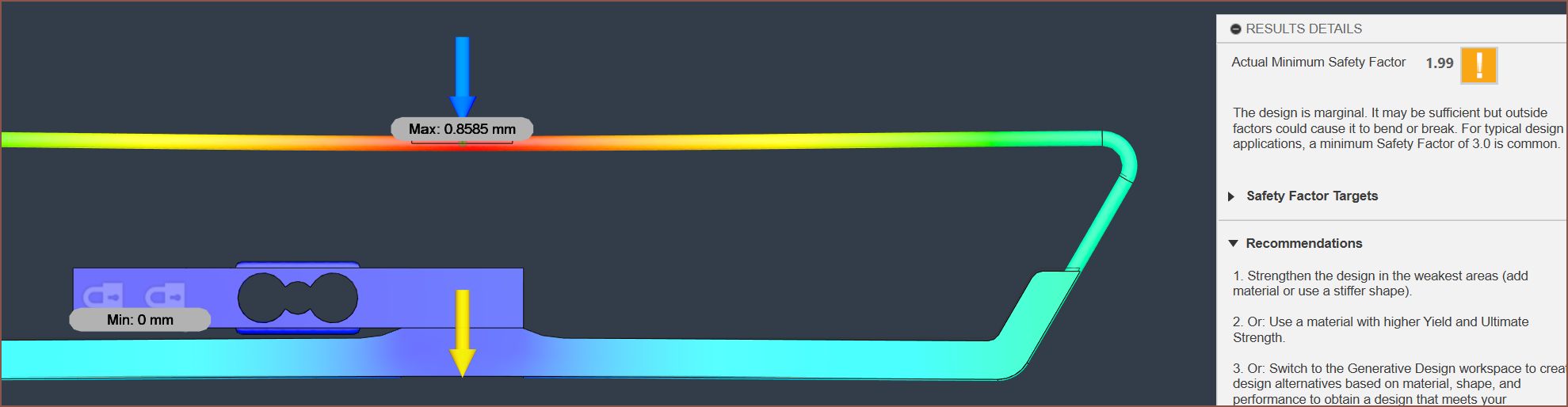
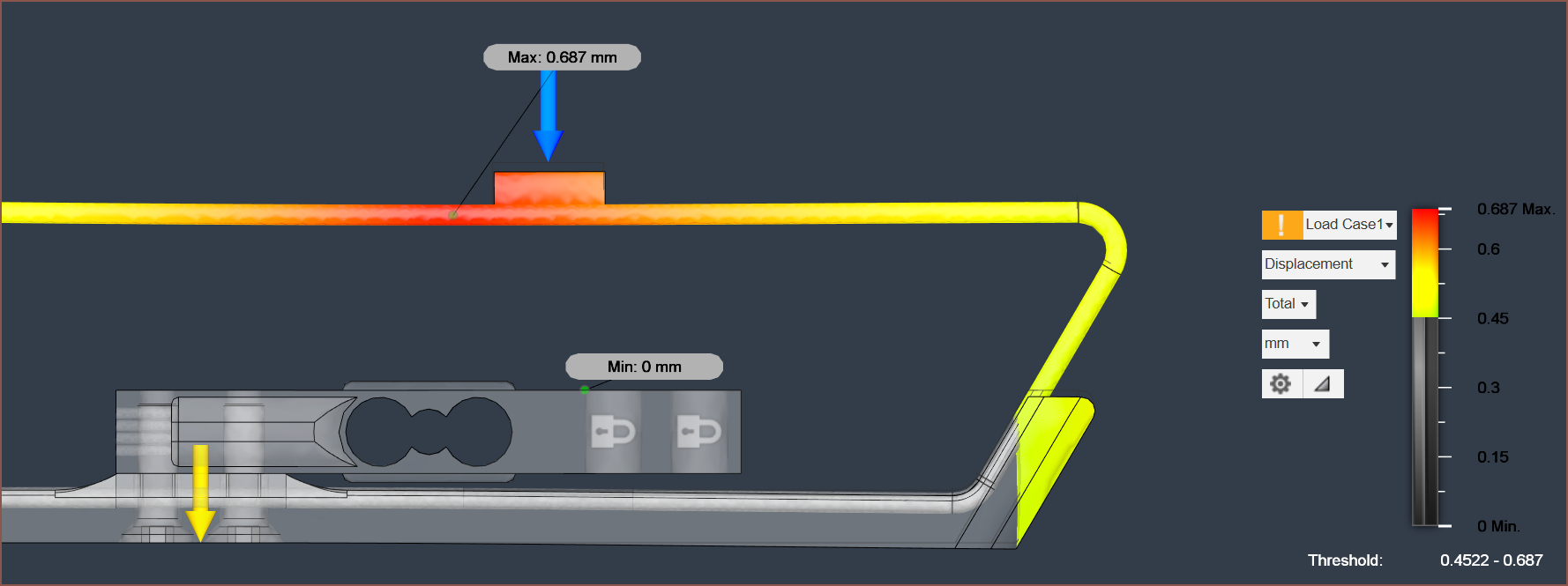
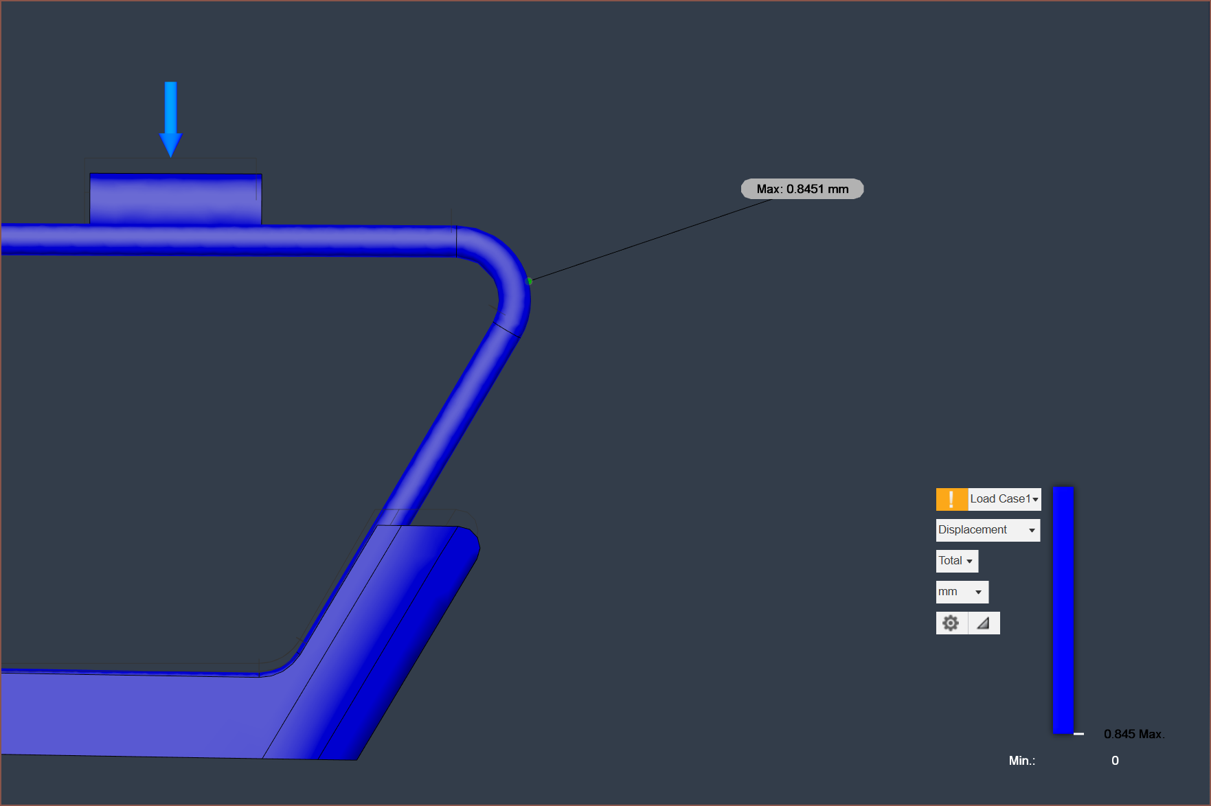
Returning to the aligned-end tubes and having them made from solid steel (so they're more like 1.5mm thick wires), I get a displacement of 0.86mm and a safety factor of 2.
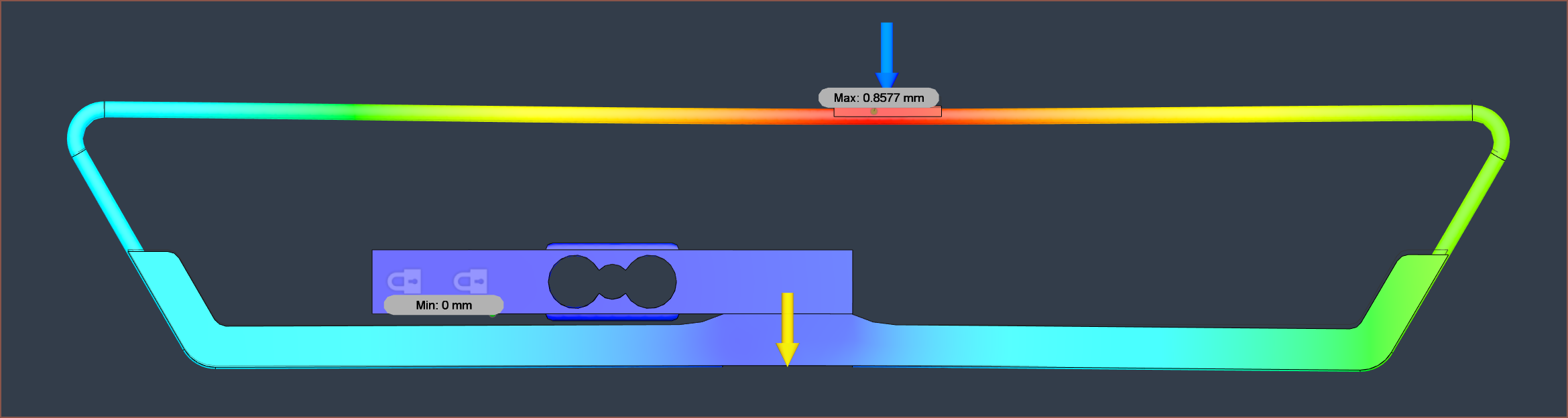
Interestingly, the displacement is still 0.86mm when the force is applied directly under another Tetrinsic, but the right side is greener than the left side. Green means over 0.4mm of displacement.
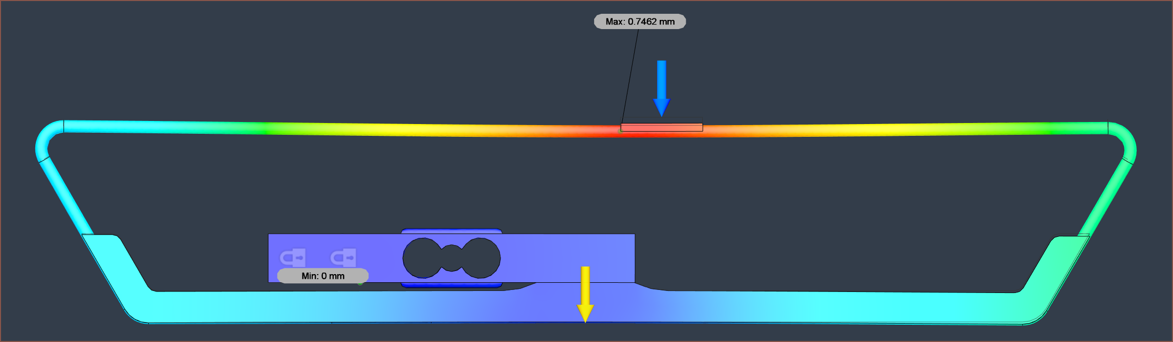
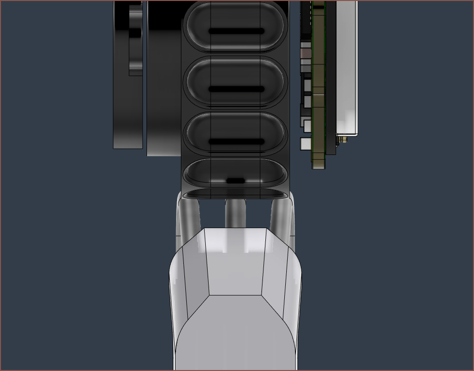
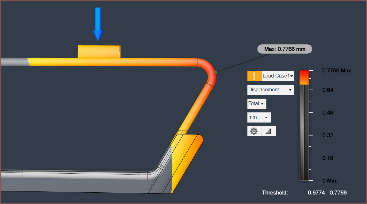
Another benefit is that, similar to a boat through water, I can print a seperator that splits the dual chain.
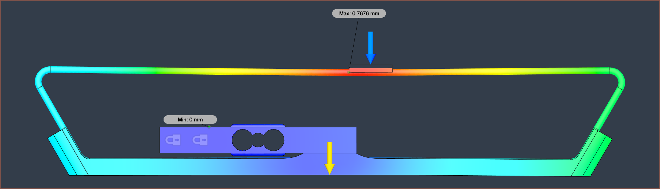
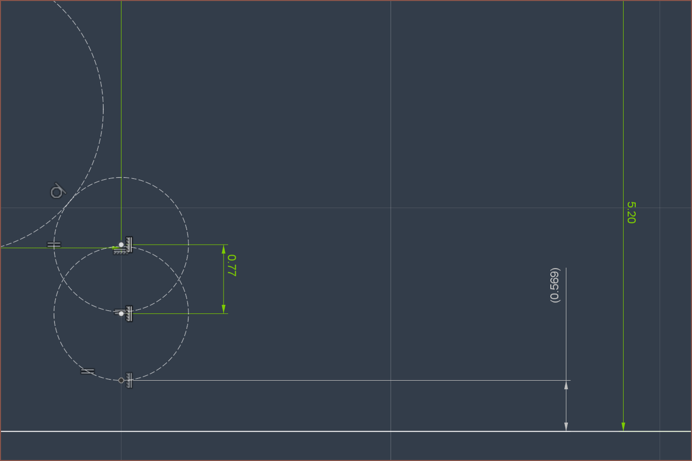
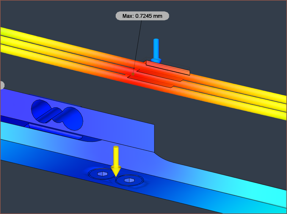
With this, I get a max displacement of 0.77mm and the base has a displacement of 0.34mm.
Considering print orientation, it's probably best if this face was horizontal instead of perpendicular to the tubes.
it seems that a height offset of 5.2 - 5.5mm would be required:
As will M3x10 countersunk screws:
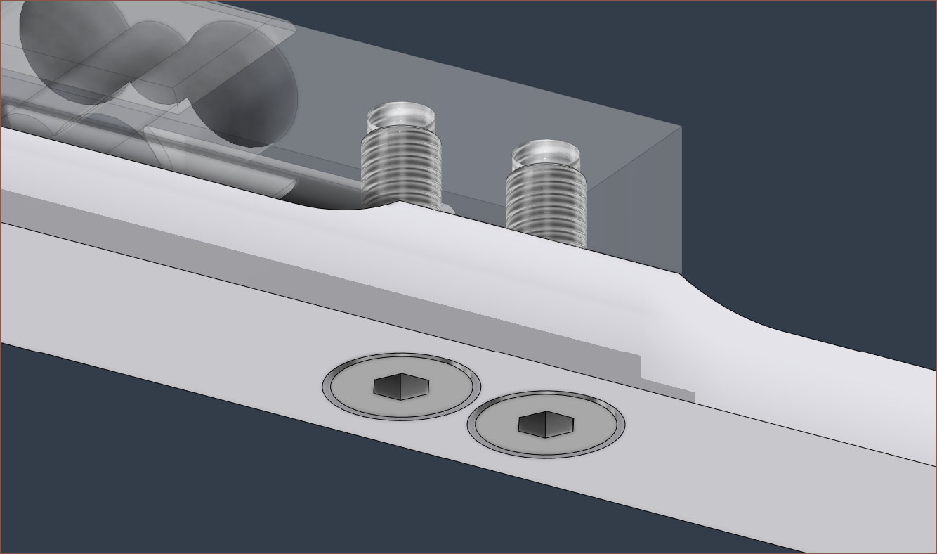
So these bolts were actually causing the simulation to fail until I did a combine-cut to eliminate the geometric intersection between them and the load cell.
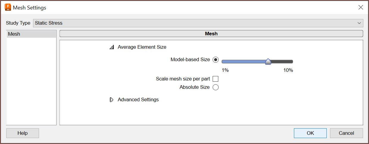
Now, for some reason, trying to simulate forces from distances over the 9.3mm set in the above simulation caused the simulation to fail. I tried a few different things and red the error logs, and I've been able to get a 25mm force sim to succeed by reducing the mesh setting to around 7%:
I simulated 50mm, and for some reason, only the "Displacement" view is glitched:
45mm worked though:
It does seem that I should also have a 0.75mm spacing below Tetrinsic to allow for this part to flex uninterrupted.
Discussions
Become a Hackaday.io Member
Create an account to leave a comment. Already have an account? Log In.