 kelvinA
The next Tetrinsic concept was going to be "Tetrinsic Concept4", but partially because this project needed a hero and partially because I was thinking about the intro music from the 33 second mark of the Fantastic Four: Worlds Greatest Heroes as I was thinking up all the improvements I could make from Concept 3.2X2, the internal code name is "Tetrinsic Concept Fantastic4".
The idea that forms the basis of this concept was from @RunnerPack all the way back in January, and is something I didn't really want to work on until after I actually had a proof-of-concept to test since it would involve more 3D printed / custom components. I wanted to be able to compare the off-the-shelf hardware solution to the more custom made solution.
Now that the 580KV motor is no longer available and I know that cogging should really be 0, I'm going to have to go through with a custom motor solution. While I was at it, I wanted to see if I could increase the stroke : body length ratio.
Initial thoughts
I thought about a solution for about an hour, and this is what I envisioned:
- Tetrinsic becomes a linear BLDC motor with integrated hall effect and pressure sensors.
- Part of the reason is so that I have more space to make and place coils.
- I move all the logic back to #Tetent [gd0090] / #Tetrescent [gd0150] like I originally planned at the start of Tetrinsic Concept1
- The motor controller is already designed to let me bundle 4 motors to one CS pin, so I just need 2 CS pins for all 5 linear motors
- I can use the 3 hall sensors that are sometimes installed into BLDC motors as the position encoder.
- I only need 2 bent
tubes, and the turning pulley can fit inside the loop instead of outside
- This assumes I can create a surface that can turn on a 7mm diameter radius
- Coils will be on the top and bottom of the linear motor section, which makes the magnetic field much more consistent and means that I don't have to worry too much about air gap
- The belt can be printed as a "Spiralise Outer Contour" (vase mode) of TPU
- The guy on the Mass Production Hack Chat said that TPU was the best in terms of layer adhesion.
- It can also be made from a magnet-band-magnet sandwich, where 2 separate magnets are stuck on each side of a thin loop of material.
- I later realised that this would mean that the Thumb Tetrinsic would have to be a different height than the Finger Tetrinsics so that the loop could go around them.
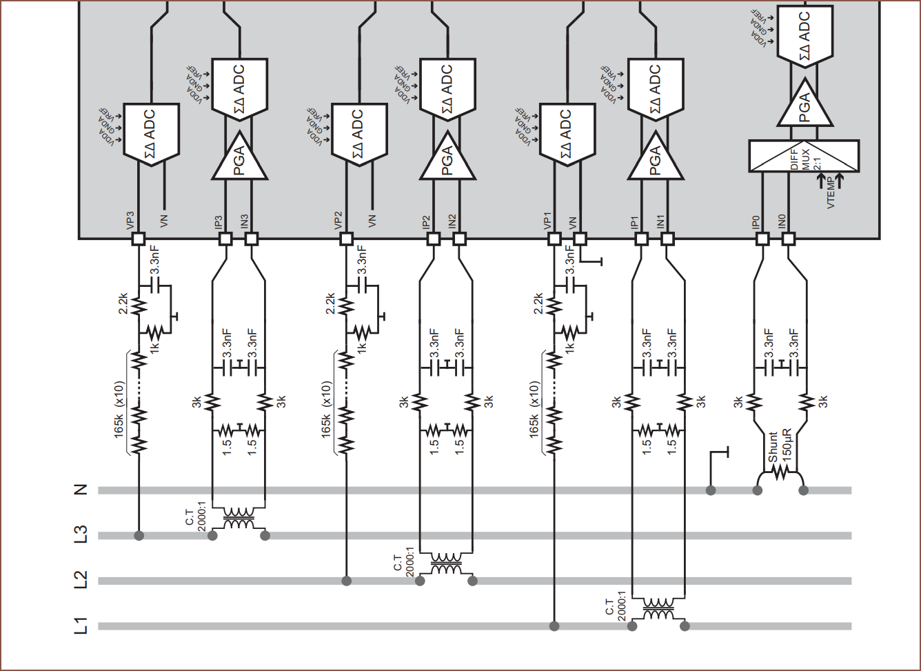
- On the connector board, I can use a 5
input Sigma-Delta, 24bit ADC for the load cells and up to 5x multi-channel
16 bit adc's for the hall effect and current sensing
- (I've been hearing multiple times that the ADC on the esp32 isn't great)
- Encasing the top-down coils in a ferrous material should further increase the field strength between the coils and the magnet embedded belt.
- See this video for more information.
My idea is to take a linear motor like the one shown below, and swap the coils and electromagnets:
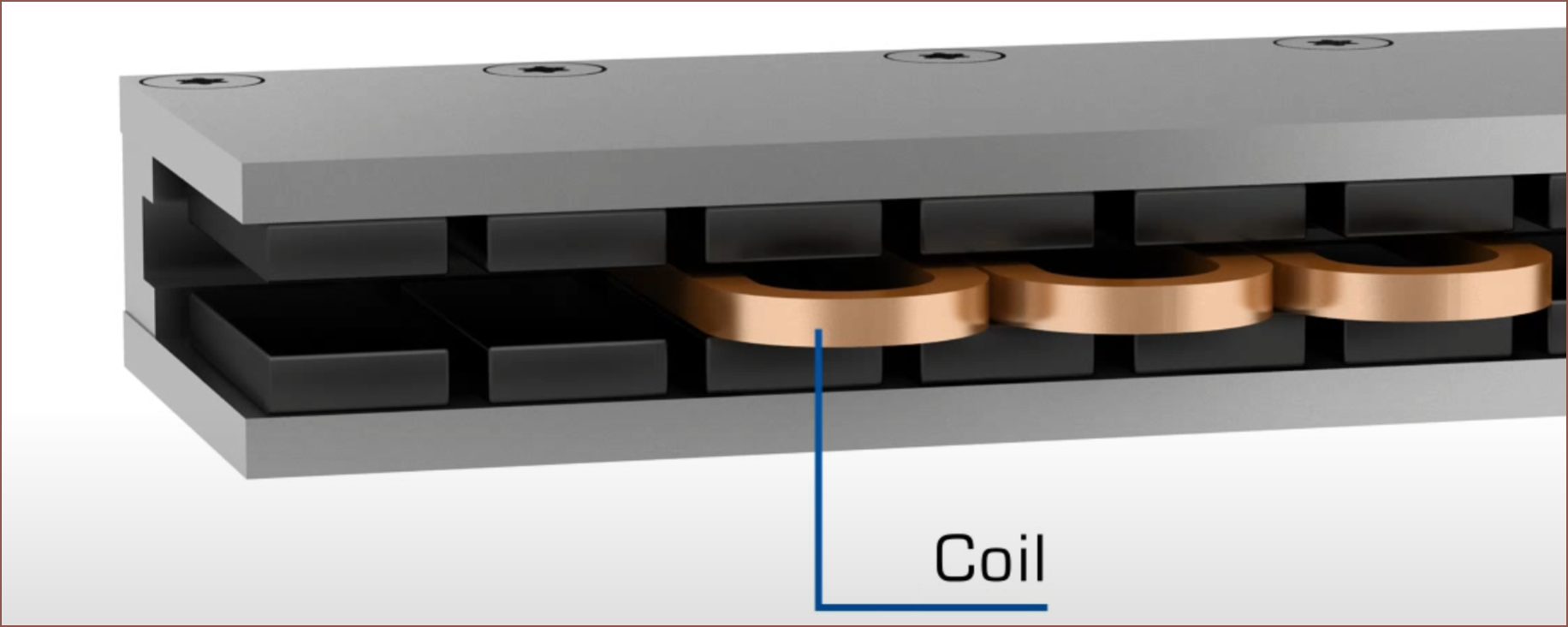
The design shown above also looks like a scaled up version of a voice coil actuator, which can be used for haptic vibrations.
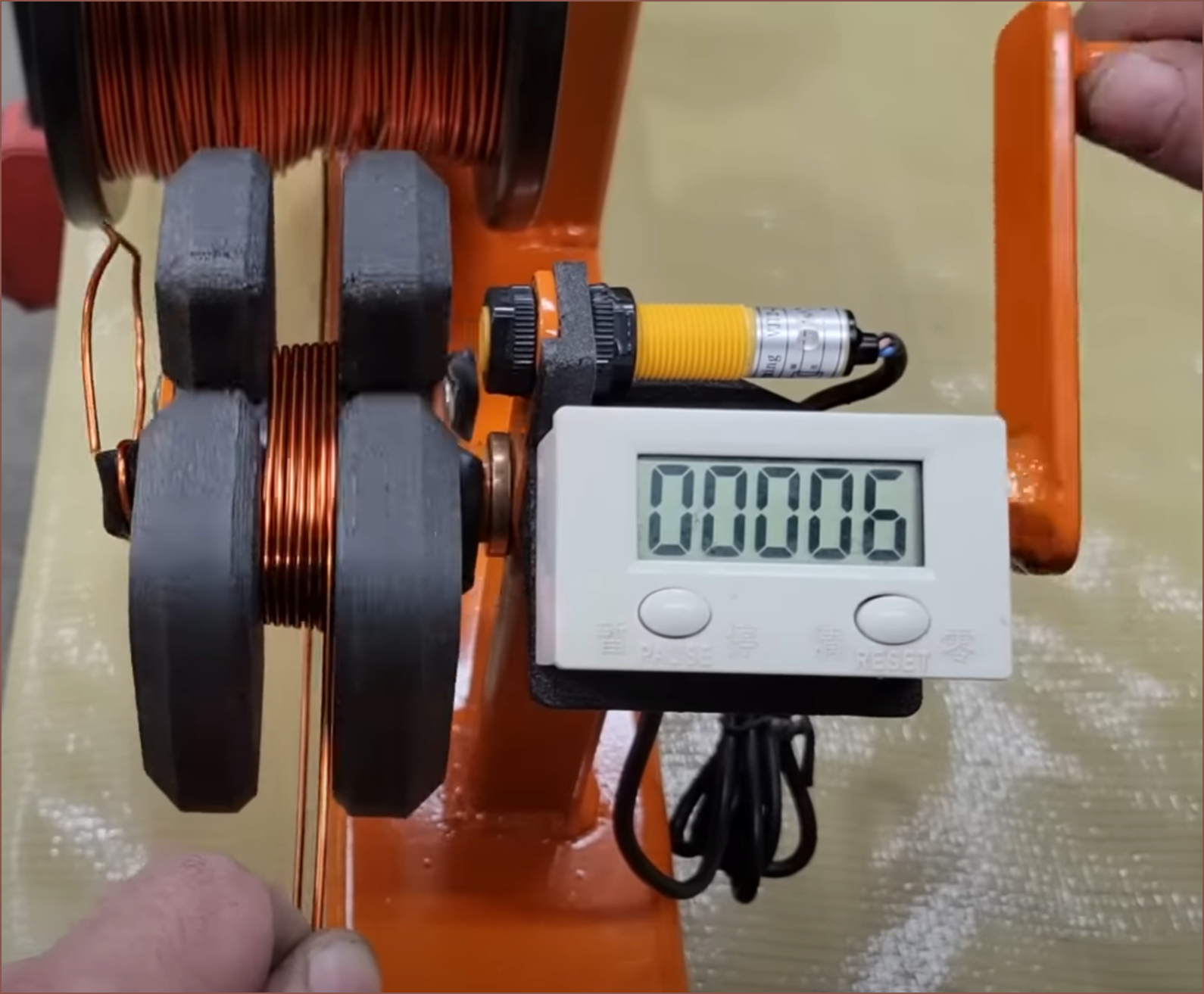
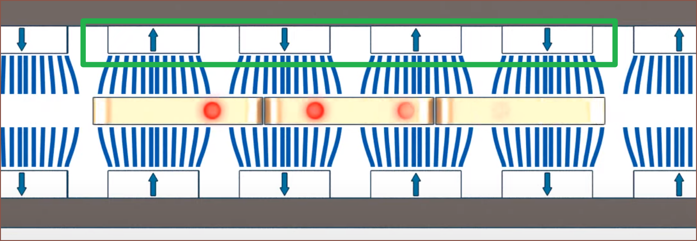
Anyway, cogging is eliminated because there's nothing magnetic in the stator. The first time I saw the video about cogging, I didn't fully grasp it, but the thumbnail actually does a good job of showing what's actually going on:
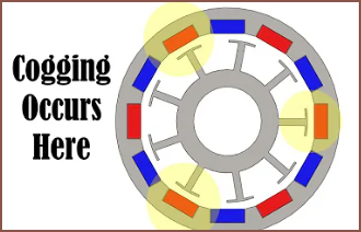
From the perspective of the magnets, the copper coil may as well not exist. The ferrous stator teeth it's wrapped around is a different story. Because of the gaps between the stator caps, there's actually an imbalance of attractive forces. (remember, magnetic materials are attracted to both north and south poles of magnets). I'd imagine that, to solve it, you'd either need to remove the ferrous stator entirely or design the stator such that the attractive force is equal across the entire perimeter.
Magnets
The first reason why Me In The Past didn't think that the embedded magnet idea would work was because I was mentally simulating with 1.5mm cube magnets. This was back when I was working on Tetrinsic (Concept) 2.0.
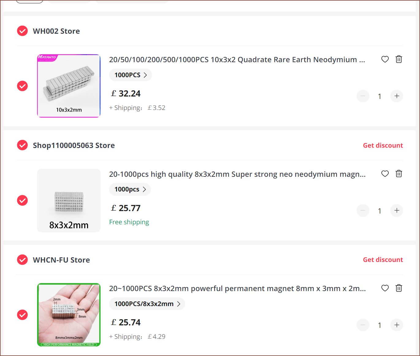
I measured the magnet length in the 580KV rotor to be 8mm and the stator laminations to be 7mm. Thus I started looking for an 8*2*2mm magnet. That doesn't really exist, but an 8*3*2mm, 10*3*2mm and 10*3*3mm magnet does. Here are some that I found:
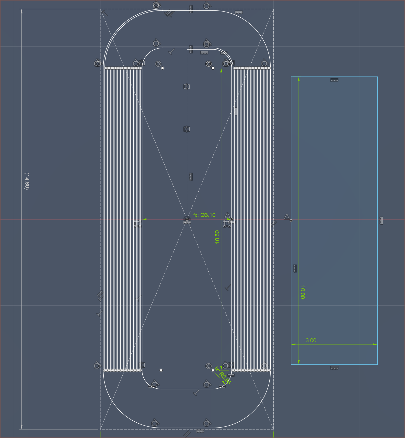
Then I sketched up an rough estimate for the overall loop:
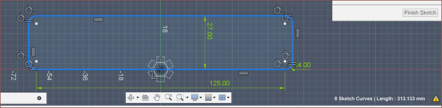
313/4.2 = 74.5238. I require "pole pairs", which means the amount of magnets needs to be multiples of 2. Thus, the min amount of magnets needed for the belt is 76.
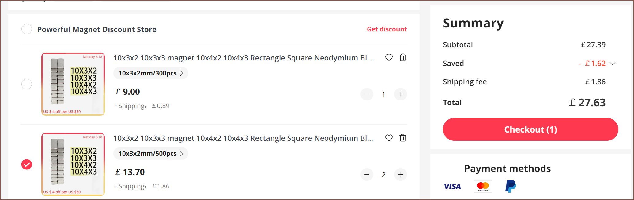
I went with 10*3*2mm magnets because the motor strength should be 25% higher, I've got a better chance of fitting the pulley in-between the sliding rods and I have the opportunity of going to a 10*3*3mm magnet if needed. For now, the 2mm magnet as the benefits of being able to obtain a slightly shorter Tetrinsic and it's more obvious than the 3*3 which faces have poles and which are just the sides. The belt would also be lighter, which means external forces would have less of an effect on the load cell readings. More on that further into this log.
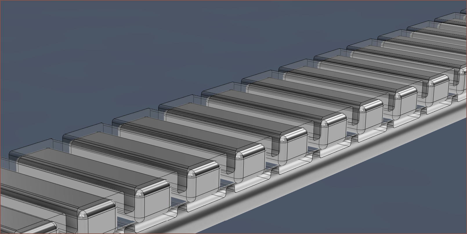
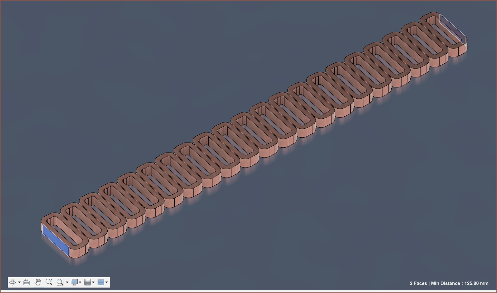
This is what the belt would look like on the steel rods:
Print Material
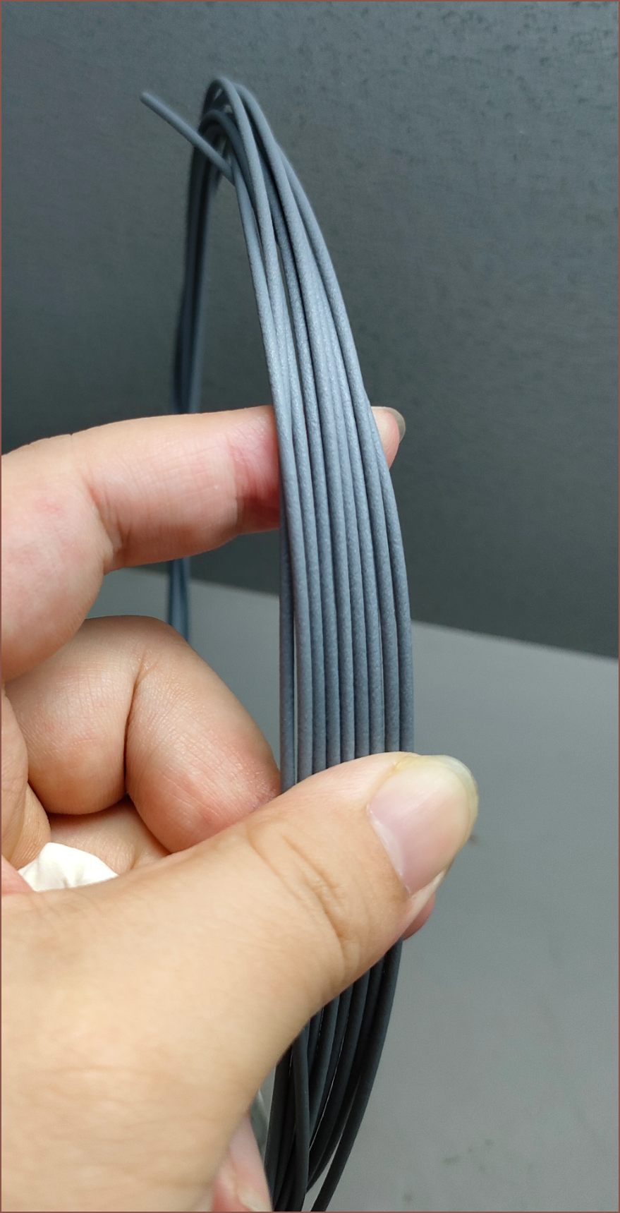
The obvious choice, at least on paper, is PBT:
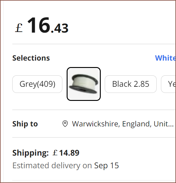
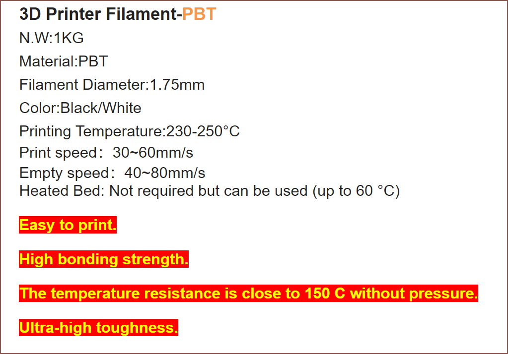
Easy printing? Doesn't even need a heated bed yet has a working temperature of over 130 degrees Celsius? High inter-layer bonding and toughness? I haven't tried it, but it's essentially obtainable unobtainium. I even tried making my own. I asked the seller what the grey looks like and I believe it looks great:
From my experience trying to extrude pellets into filament, I can only imagine the only imperitive step before printing this material is to print a temperature tower. This material has a very sharp melting point.
Accelerometer
The mass of the assembly responsible for measuring the pressure of each finger is now higher, meaning it's even more likely that acceleration and orientation changes will cause Tetrinsic to think that it's being pressed when that's not the case. Thus, I need a 1 axis accelerometer that's in the same axis as the force sensing part of the load cell.
Long story short, the BMI160 is still the best chip for this. I looked into the sample rates, and it looks like I should target 800 or 1600 samples per second:

The amount of samples per second directly affects the latency of the overall system. The last thing I want to find is that my fingers are feeling a haptic event for one layer but the force I'm applying means I'm already in a layer above / beneath it.
As long as the data is clean, 800SPS should be fine.
New Feature: UVC sanitation
Whilst researching and planning out this concept, I had a realisation. The belt can be electronically moved out of view, I could place a UV LED on the underside and heavily touched items such as keyboards and smartphones gather a lot of microorganisms. I also remember the below video I recently watched on "Big Hand Dryer" vs "Big Paper Towel", namely the part when Half As Interesting said "[Big Paper Towel] hit 'em on hygiene.".
I quickly searched to see if UV LEDs have been used to sterilize keyboards, and I found this video from Kensington on a product called the UVStand:
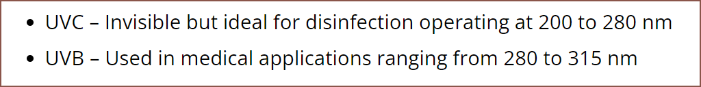
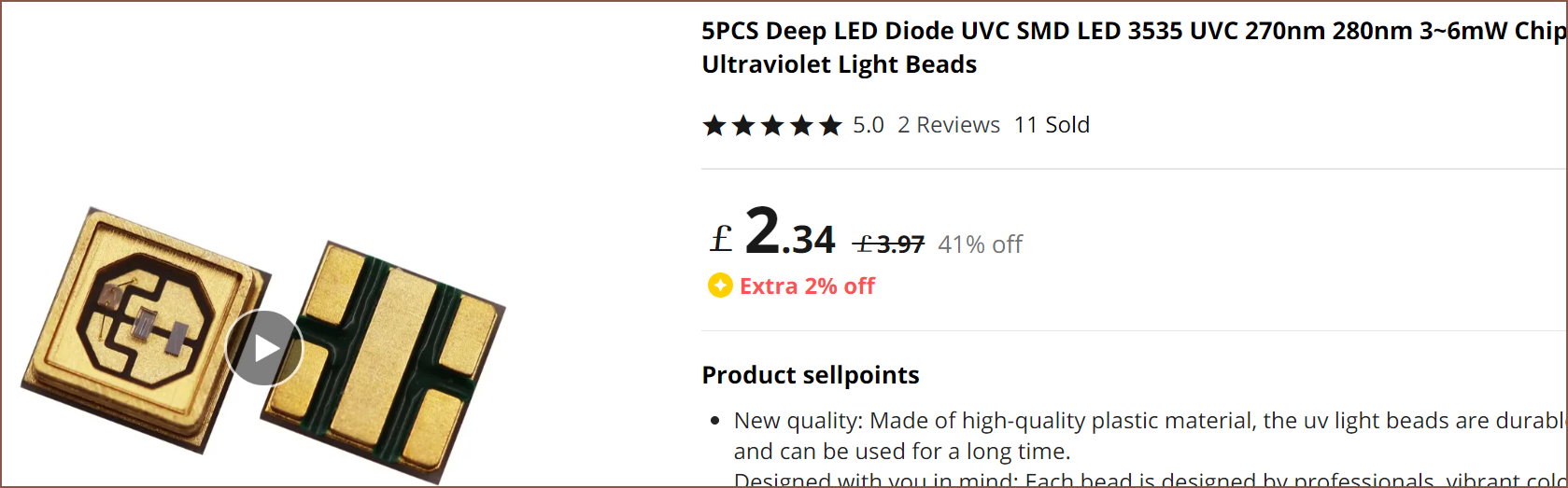
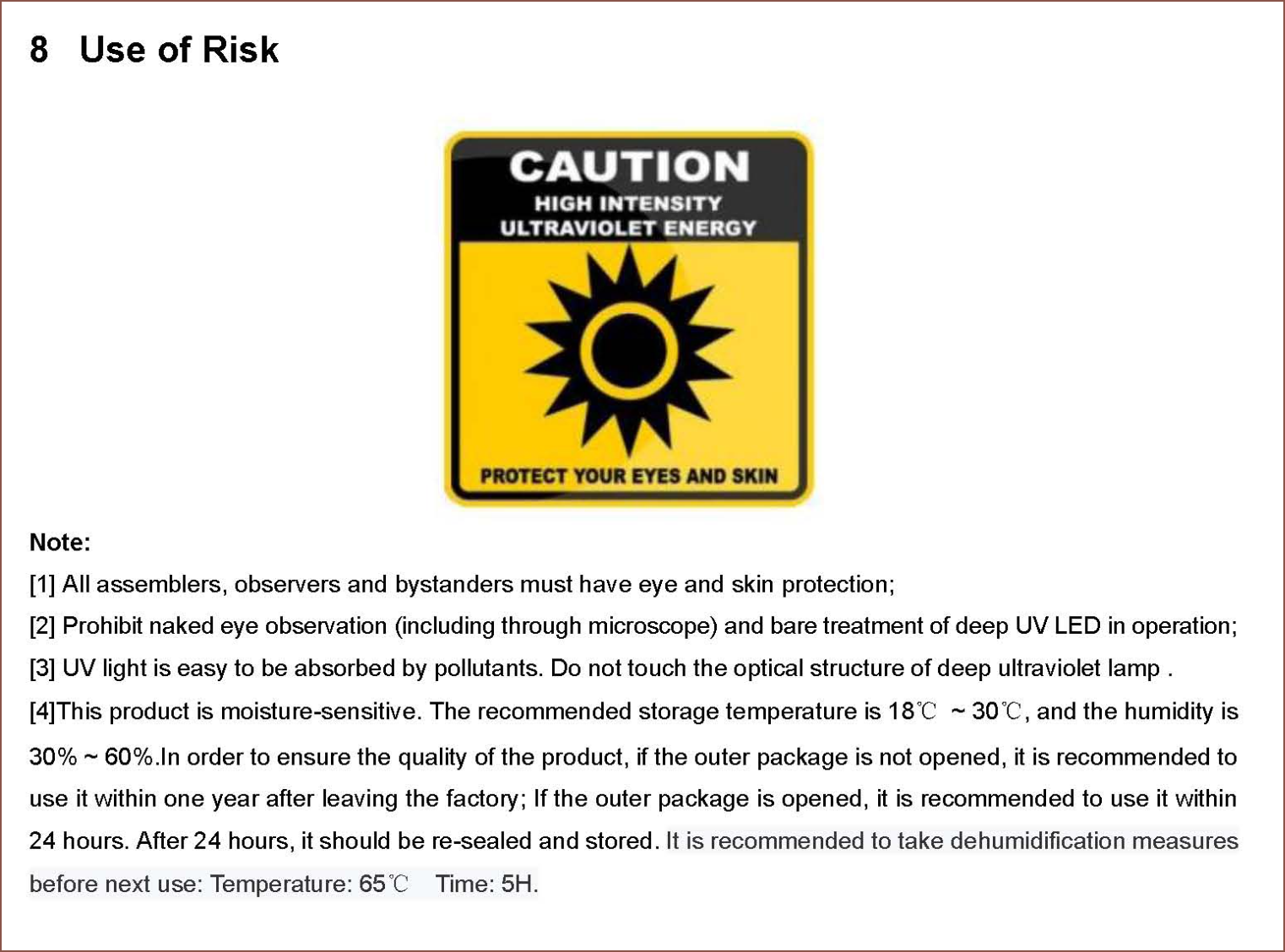
Then some quick research on wavelengths, protective eyewear and purchase options followed:


Coil Creation
I knew that the coils were going to be the most tedious out of this entire operation, so I wanted to look into strategies.
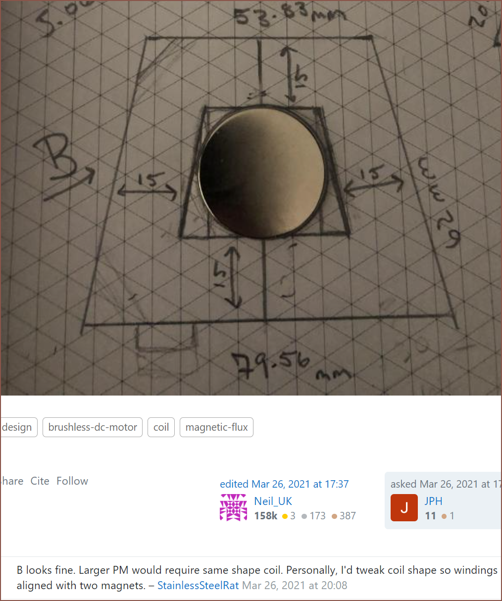
This video on YouTube said that coils of copper inside the perimeter of the magnet wouldn't generate any energy (he's making a wind turbine), and seems to be confirmed by looking at a StackExchange question:
For this application, the Kv should be as low as possible. This means that the turn count of the motor needs to be as high as possible. However, the higher the turn count, the longer it would take to coil, maintaining coil shape quality.
On my research travels, I found this image:
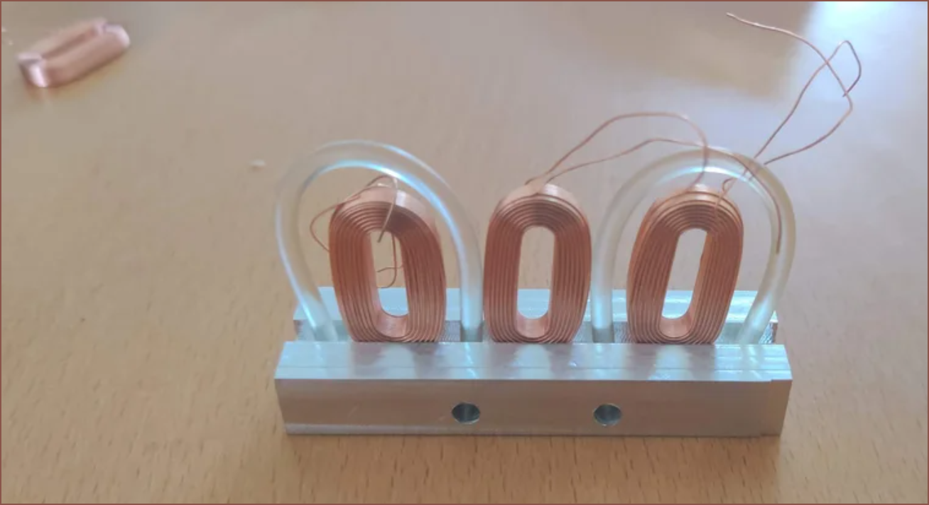
The coils were actually bought:
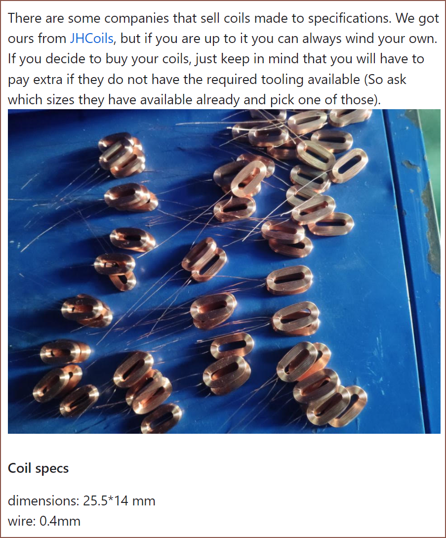
It doesn't seem like they'd have the size I'm looking for:
So I did some more mental simulations and for conductivity of heat, electrical resistance, number of turns, ease of coil manufacture and quality of coil geometry, I'm not really seeing the drawbacks to using copper foil here:
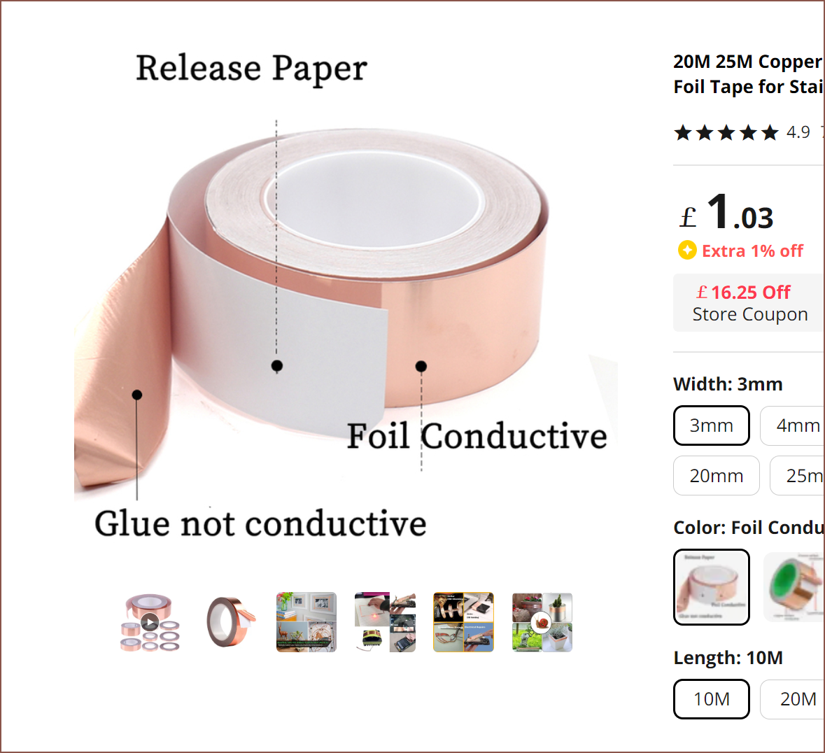
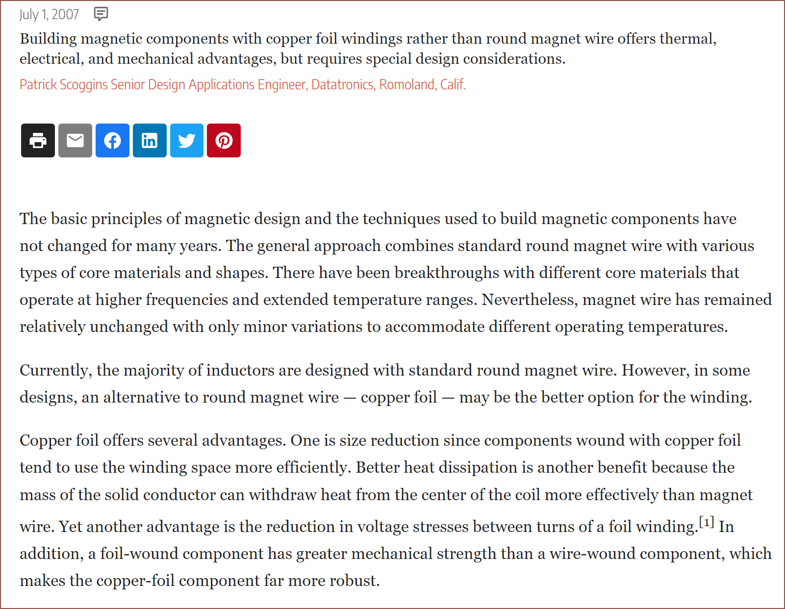
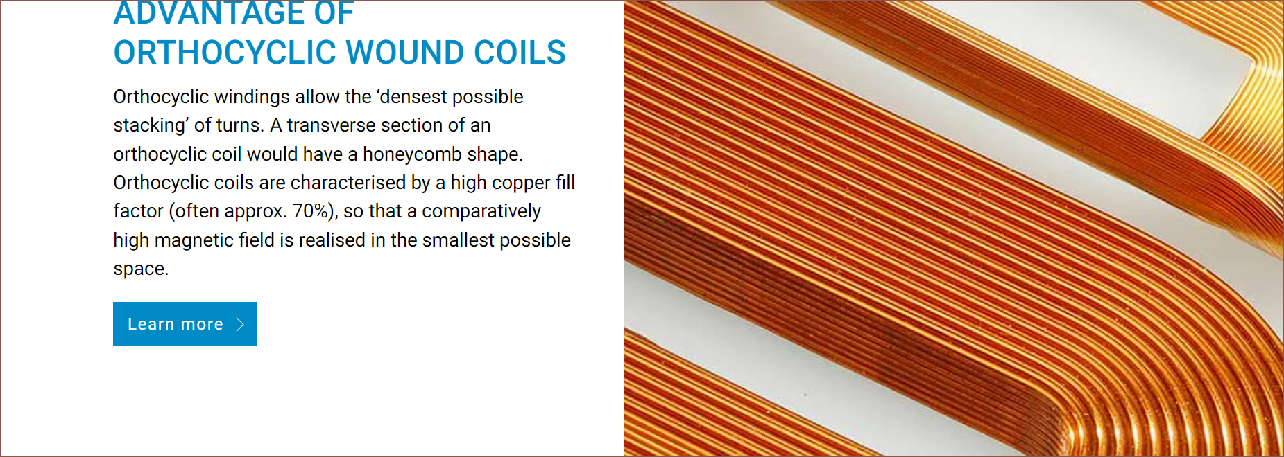
I looked around and found one with a datasheet, called the AT0525 35 Micron Copper Foil Shielding Tape. It's got a foil thickness of 0.035mm and an adhesive thickness of 0.03mm for a total thickness of 0.065mm. I did some more research and found out about orthocyclic wound coils.

The amount of spacing needs to be 3 coils for every 4 magnets.
I'm planning on using a 4.5mm magnet-to-magnet spacing, which means that the max coil width can be 4.5mm*4/3 = 6mm.
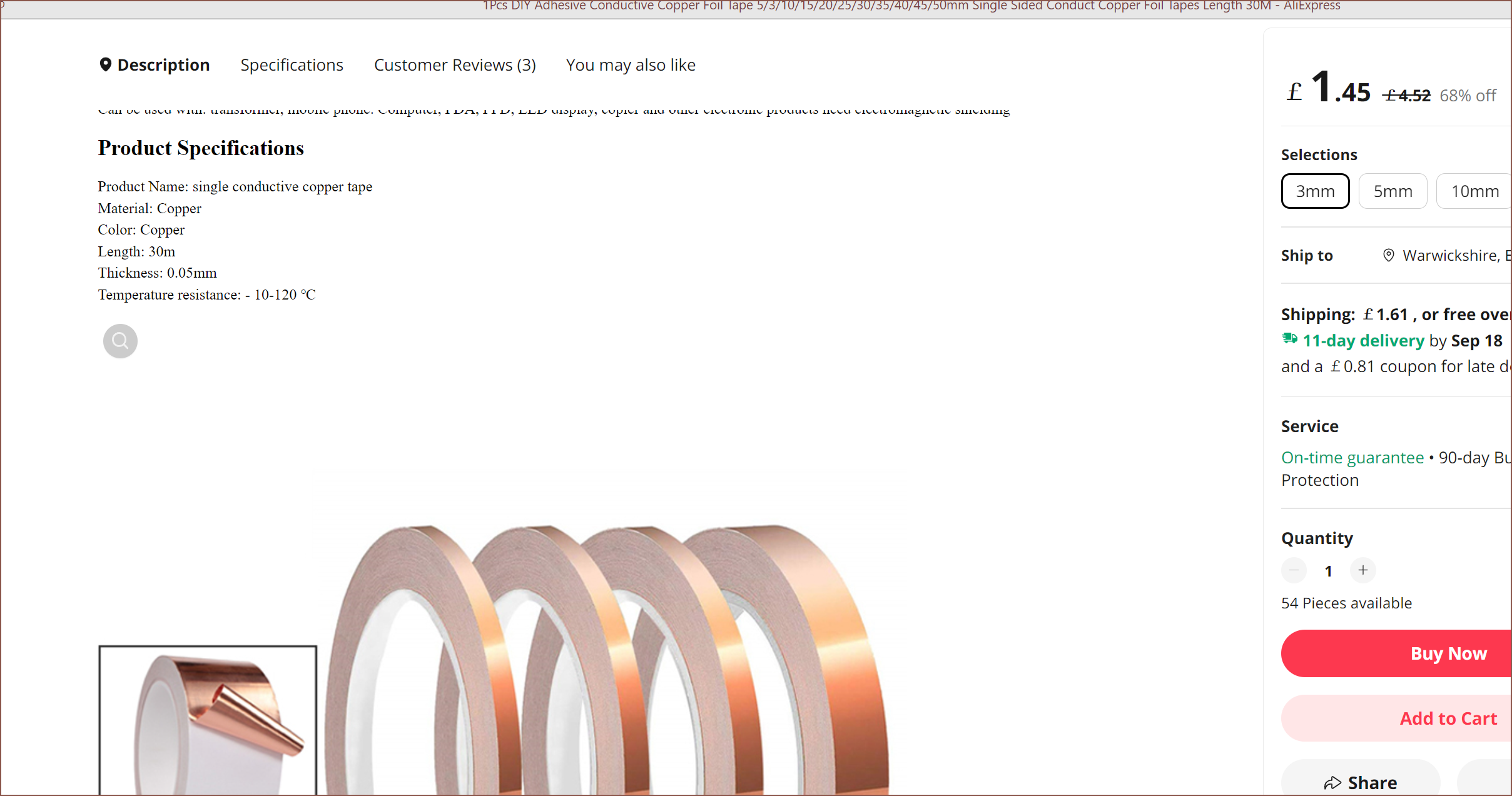
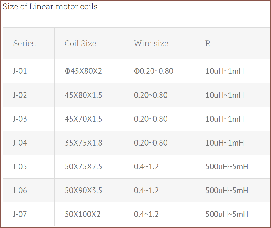
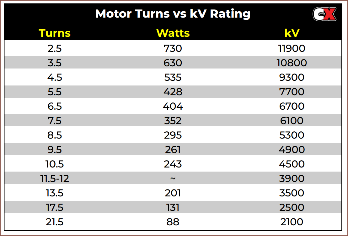
I found this 3mm foil that is only conductive on one side which has a thickness of 0.05mm and a length of 30 metres. I also found this table that gives me a rough idea as to the turn count relationship to Kv:
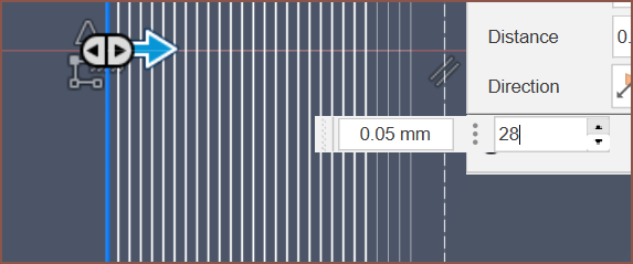
It seems that I can fit about 28 turns and still have space for an insulator such as Kapton tape to go around the entire coil.
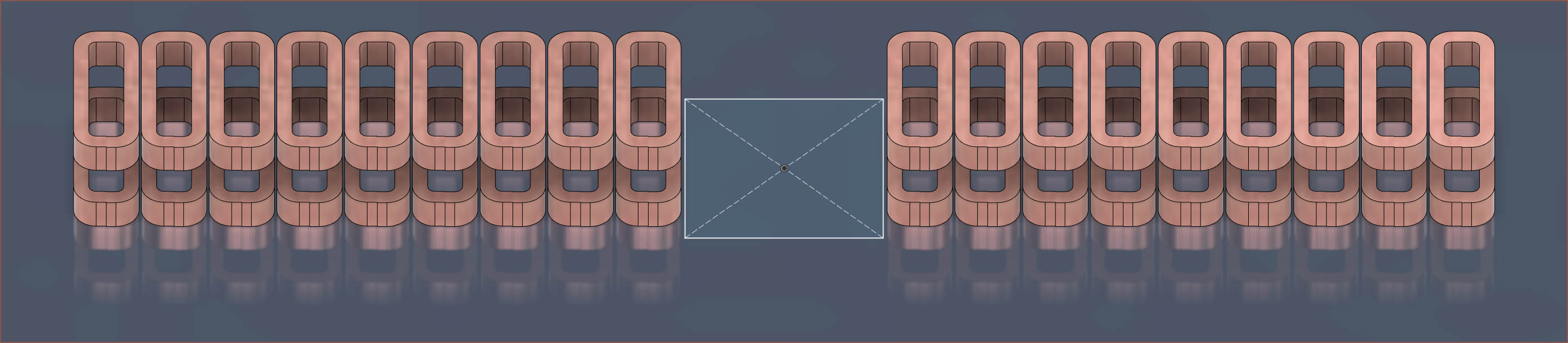
The middle set of 3 coils are removed, and in their place is the 17.5*17.5mm PCB(s) that have the accelerometer and UVC LED. As you can see, each Tetrinsic would use 36 coils, meaning that I'd have to make over 360 of them for 2 Tetrescents, using over 305 metres of foil in the process. Not having to precisely wind thousands of metres of 0.1 - 0.2mm wire onto a 3mm tall coil is the main reason of attempting this foil method. It should be possible to create 9 foil coils at once if I design a suitable jig.
The Analog To Digital Converter
This was the part that took the most time and research. This was mainly because it was the difference between Tetrinsic costing £17.20/ea and as much as £23/ea (which is a difference of £50 for 10 of them).
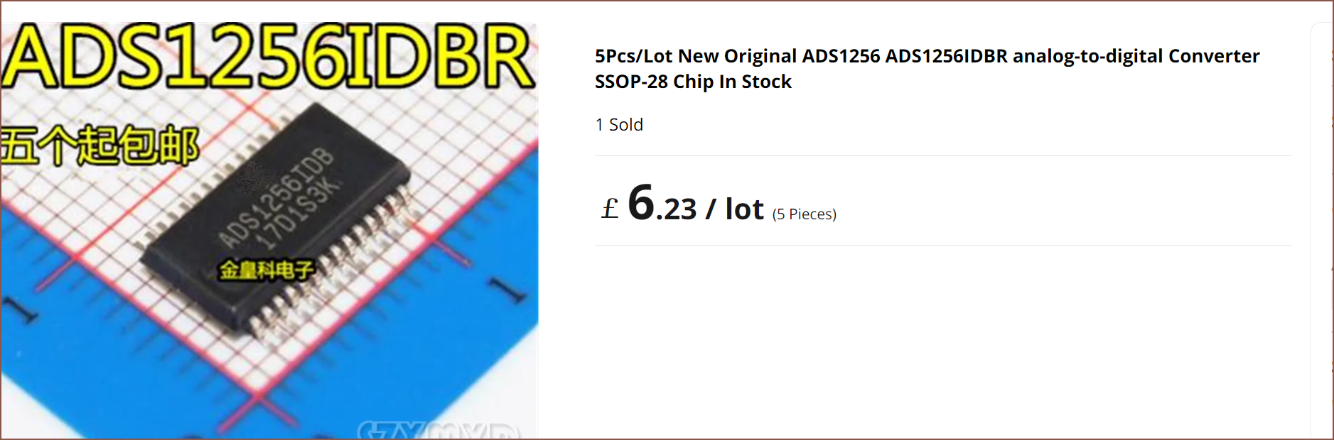
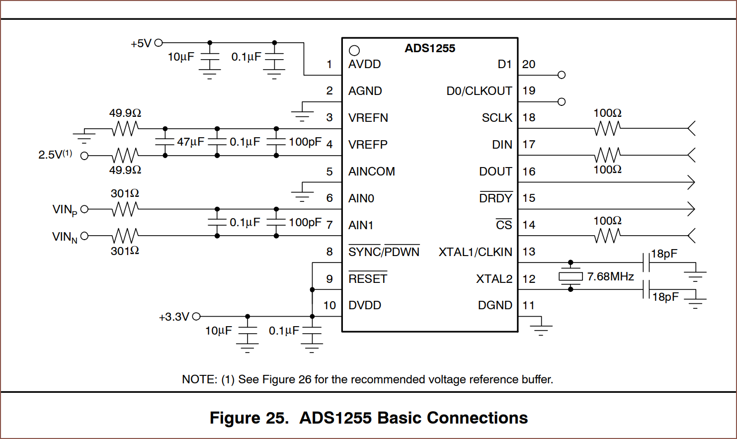
The first thing I did was search Digikey and found out that the ADCs that I can use still start at over £3/ea. Thus I quickly turned to AliExpress and found the ADS1256:
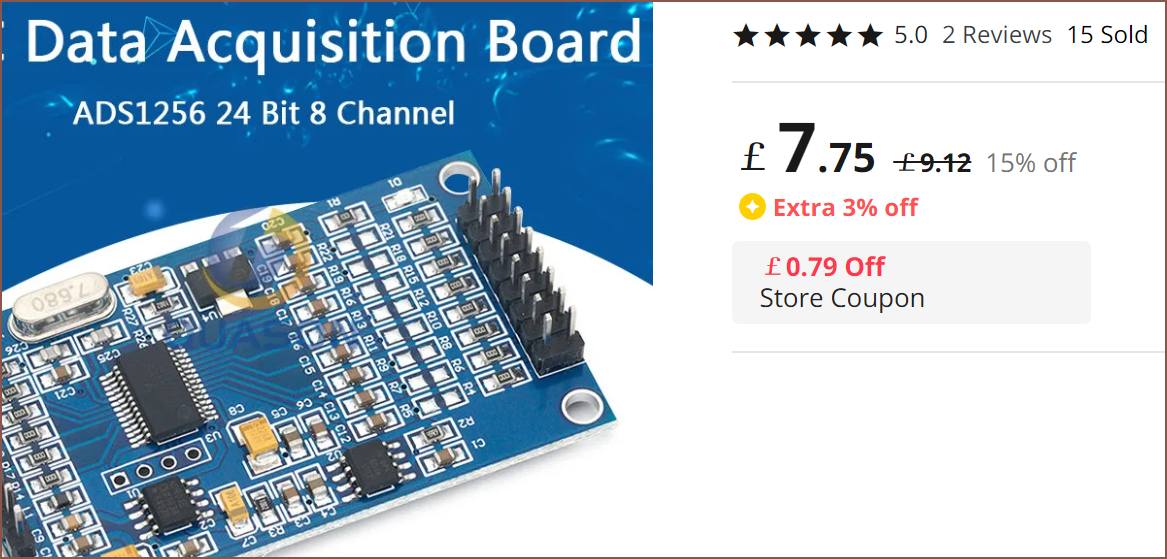
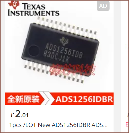
£2 is kind of odd, since on Ti's site, it's like $12:
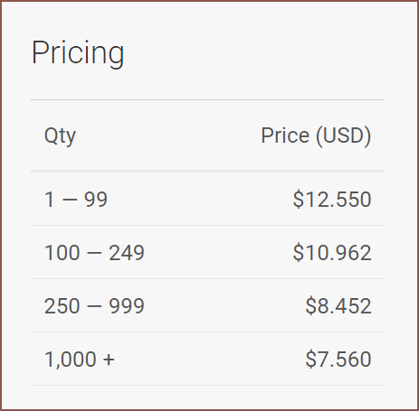
Well there were many sellers selling it at under £2/ea, with the cheapest being £1.50 after tax:
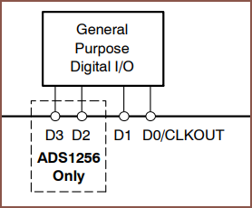
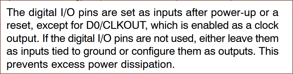
The first things I noticed was that I could save a clock pin and use a crystal (though I'd rather avoid it) and that there was even an IO extender in here:
The ADS131 series is a lot rarer on AliExpress. I couldn't find the M06 but I was able to find the M08 edition:
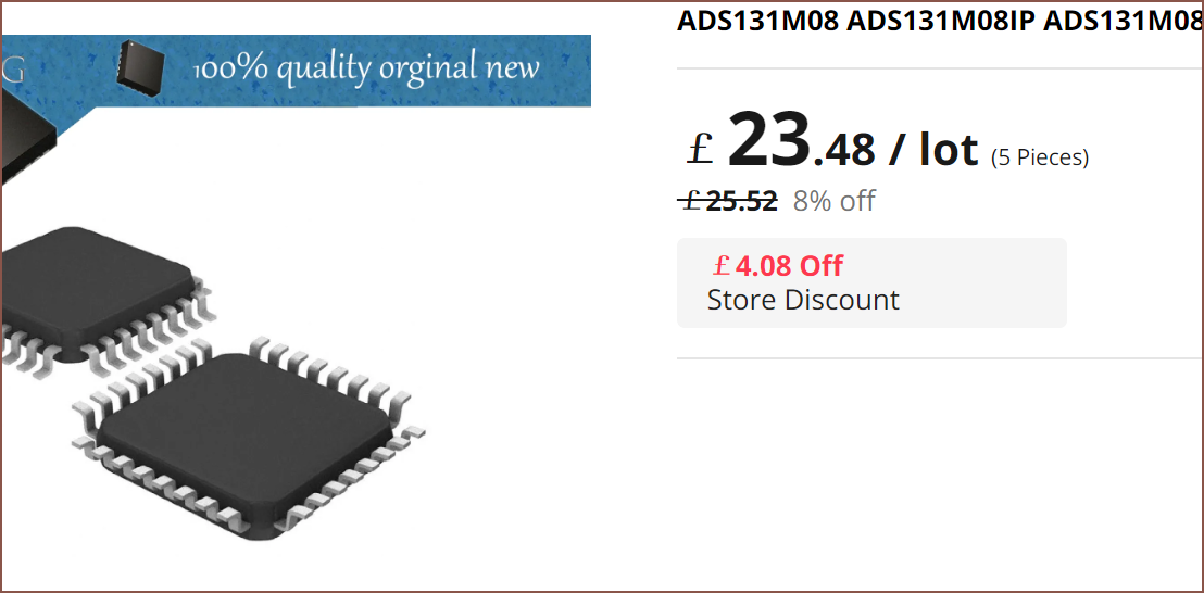
This is £5.80/ea after VAT.
I then found the ADS1262, which is a 32 bit ADC
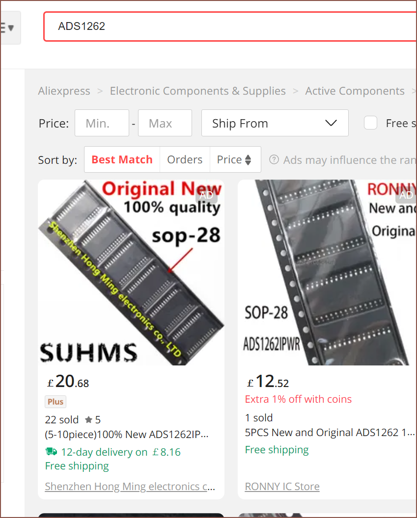
This thing also has IO, but it's shared with the ADC inputs.
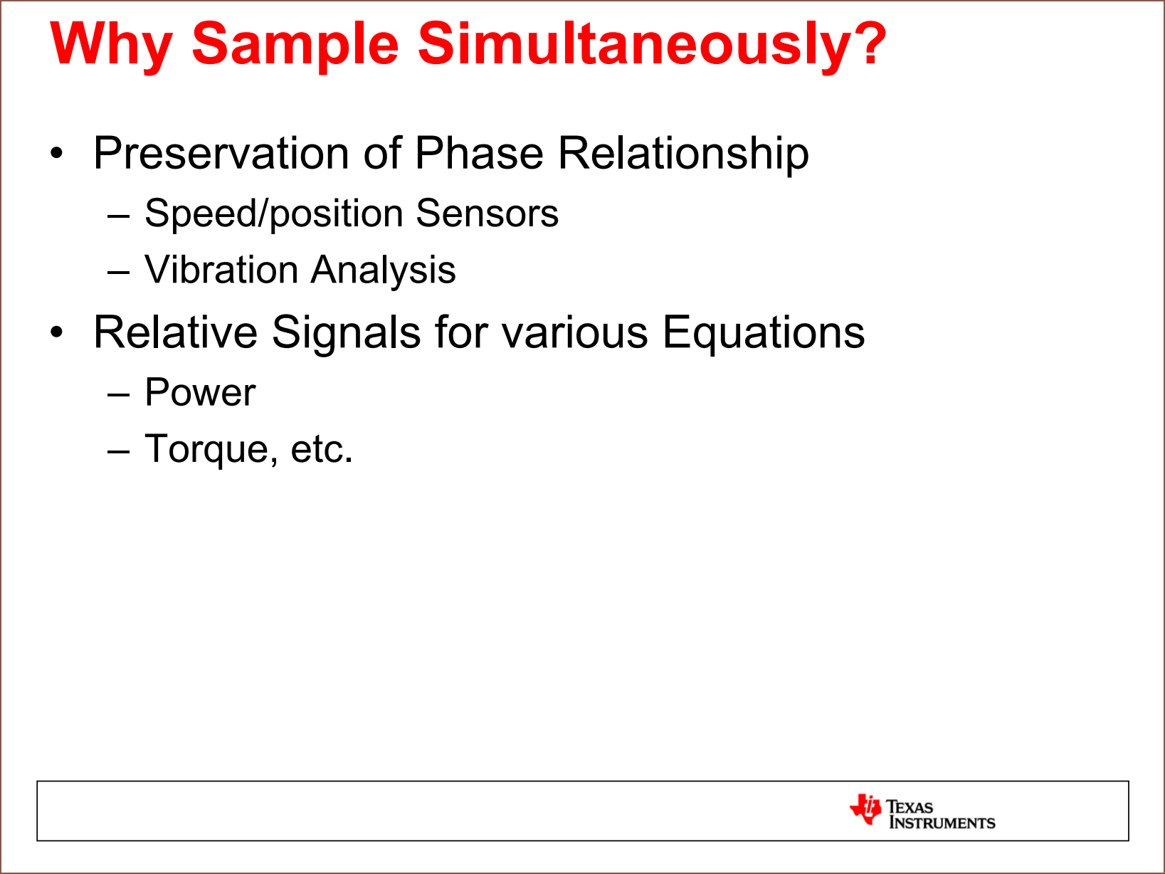
Now, the ADS131 series is the only ADC I've found that can simultaneously sample. The other two, as well as the MCP3564R I'll mention shortly, only have a single ADC. There's also the ADS1263 that has a 32 bit and a 24 bit ADC, but the 24BIT ADC can only do 800SPS (which I was planning to split across 3 current sense pins), the datasheet suggest that this ADC has less than 12 bits of effective resolution at that full speed, and costs about the same as the M08 on AliExpress. This is one notable slide from Ti that I saw when considering my options:
Moving on, the less things I need to sample, the better. It turns out that I could only sample 2 of the 3 sense pins and then calculate the current in the 3rd one:

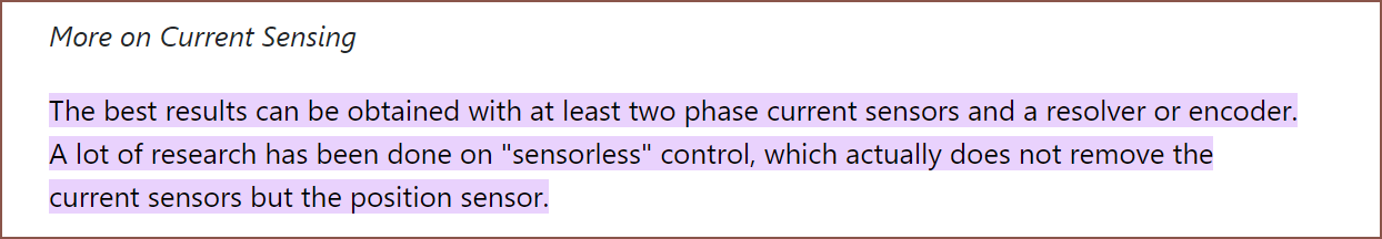
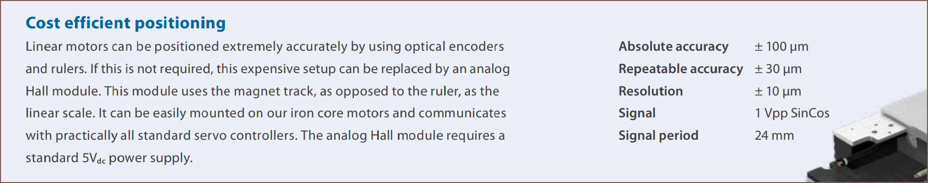
I'd imagine that I can also have 2 hall effect sensors for position:

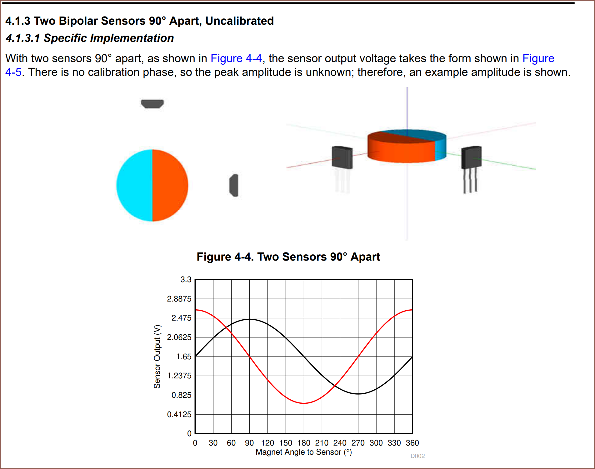
A little side note is that these sensors have more in them than I thought:
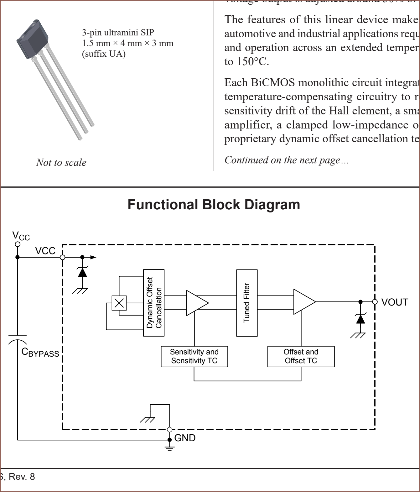
There's the below linear motor that, even though it's only got a 34mm mover length and 2mm thick magnets, it can generate up to 10N of continuous force and also uses hall effect sensors to obtain position from 2 signals:

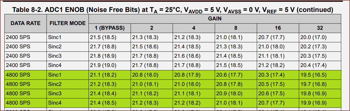
Back to the ADCs, that essentially meant that I have 5 or 6 sensors to scan, meaning that I need 4000 - 4800 SPS if aiming for 800 SPS across all channels. Below are the Effective Number Of Bits (ENOB) of some of the options.
32 Bit Multiplexed:
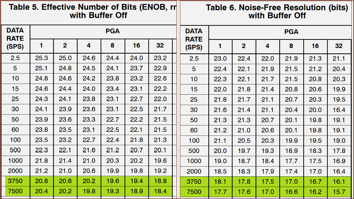
24 Bit Multiplexed:
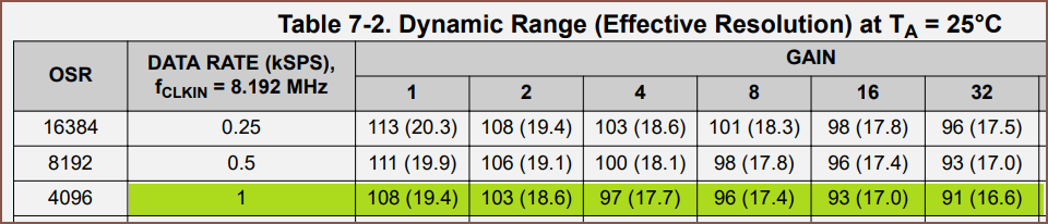
24 Bit Simultaneously Sampled:
And some research suggested that to convert Effective Resolution to Noise-Free Resolution, I take away 2.7 from the number. Looking at the difference of the 24-bit mux, I believe that is the case.
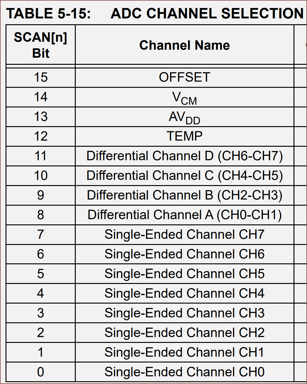
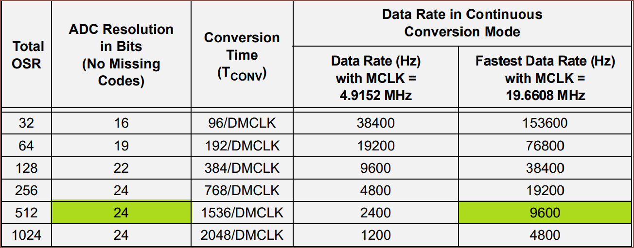
I then looked into scanning the inputs, and found this in the 32 bit datasheet:
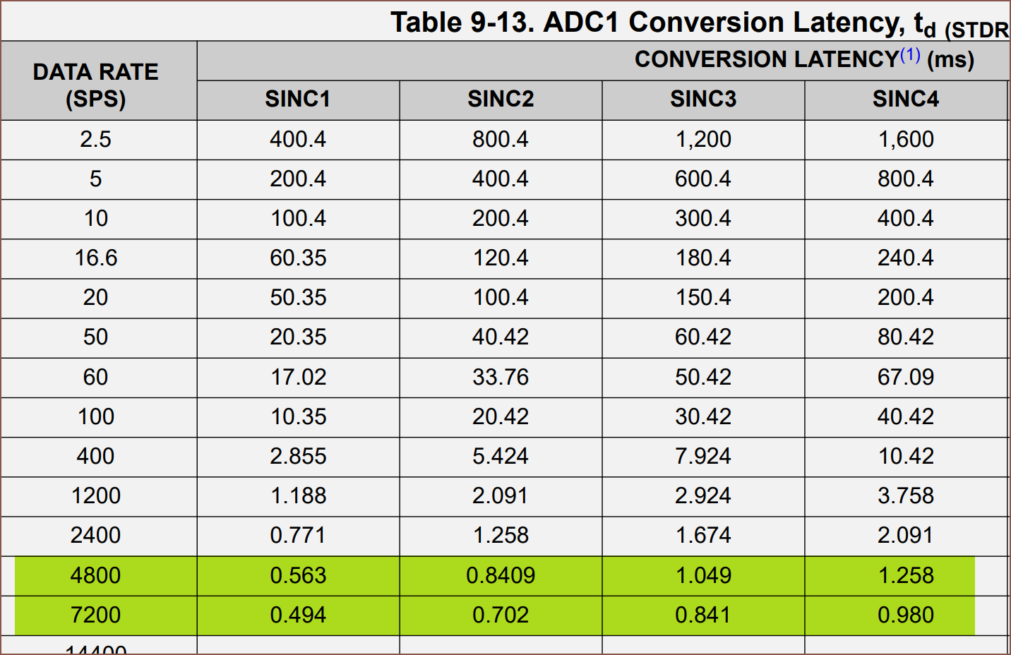
1/4800 * 1000 = 0.2083 ms. The only data rate option that can get that is the 38400 SPS option. Looking at the noise free bits, it tanks to 12.5 across the board doing that.

The 19200 SPS option has a settling time of 0.337ms, resulting in a top frequency of 2967Hz. I'd have to go down to 400SPS to use this. That still exceeds the touch sampling rate of most gaming smartphones (360SPS), but I'm not sure if it's fast enough for haptics. It also increases the latency between the measurement of the sin and cos hall effect sensors. The above table uses an external 5V reference, and it sounds like the reference voltage only affects 38400SPS:

For the 24 bit mux, it's maximum is 4374Hz:
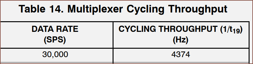
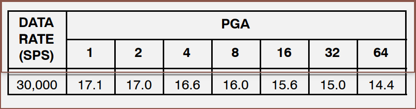
By sampling 2 sense pins, I could still obtain 800SPS and I'd get 15 bits at PGA = 32.
The reason why I'm looking at the noise-free bits is because of this:
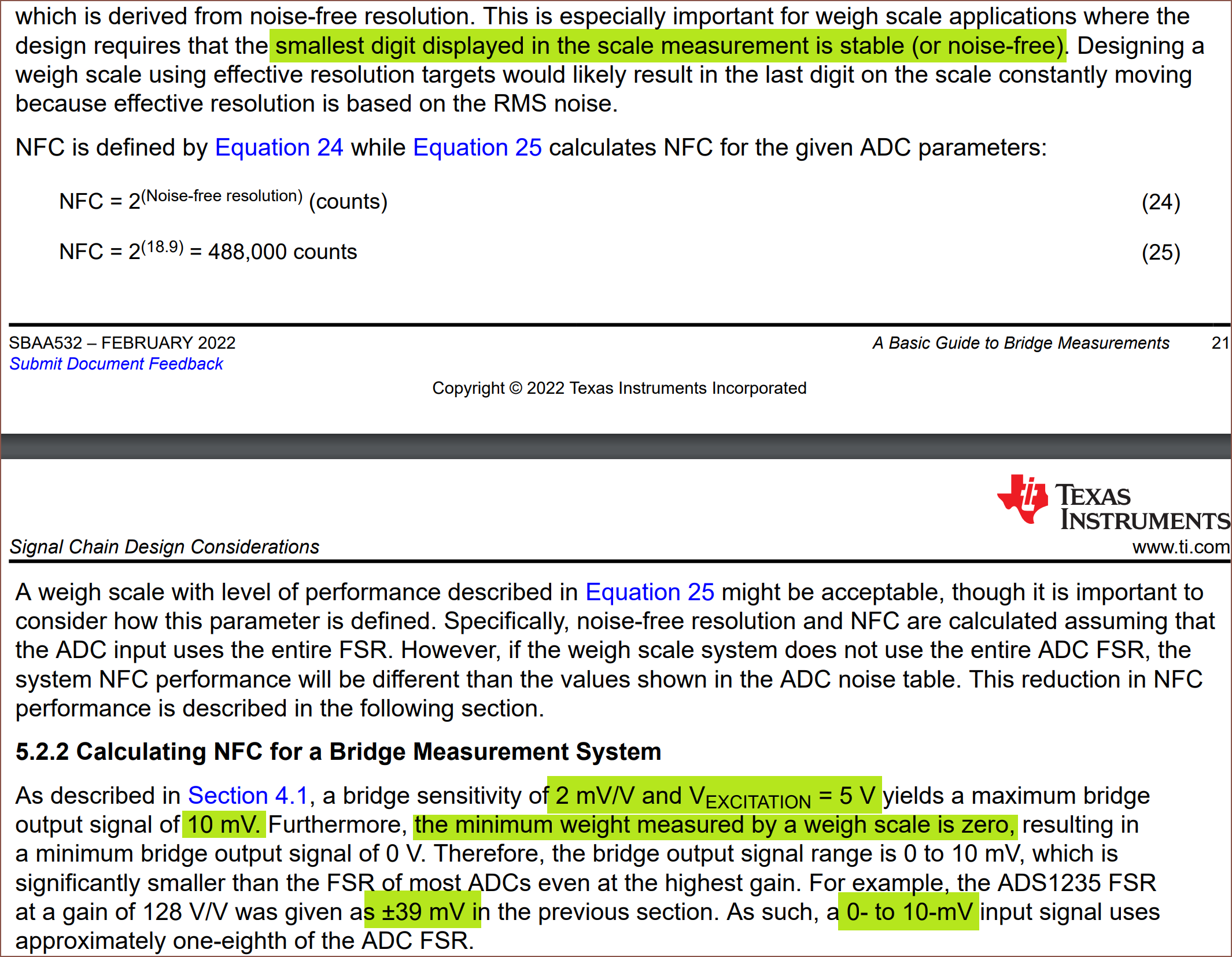
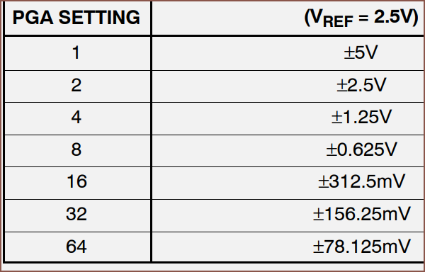
Now, the load cell (well, a very similar load cell to the one in the precision scales) states that it's excitation is 1mV +/- 10%. That seems to mean that with a 3.3V source, I'd get +/- 3.3mV of full scale signal. The below is the 32 bit ADC's mention of PGAs:
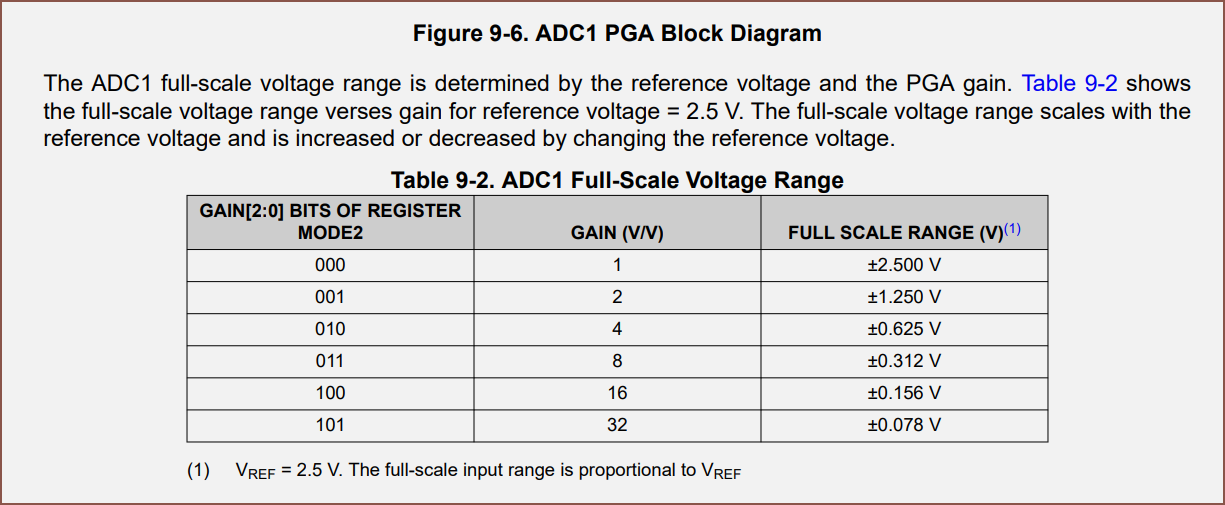
That's like... 78mV. For the 24 bit mux, it's the same for the highest PGA value:
The issue is that it actually doesn't come with a reference voltage source:
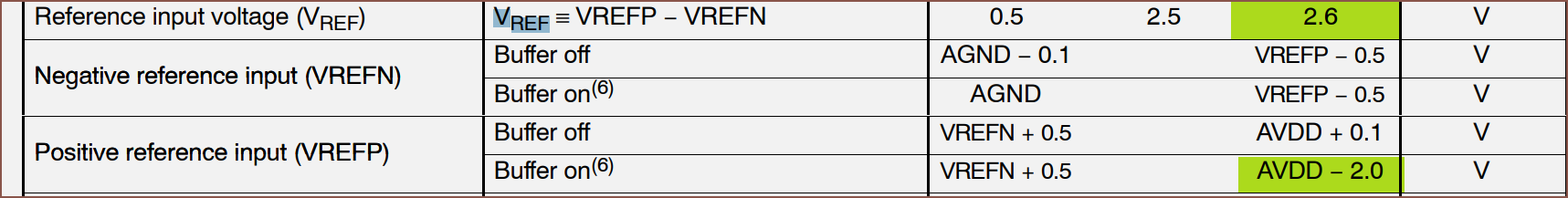
I can't use 3.3V for the positive and GND for the negative terminal because Vref has to be less than 2.6V. Also, the buffer needs to be kept off unless I want to be using something like a 1.25V reference voltage.
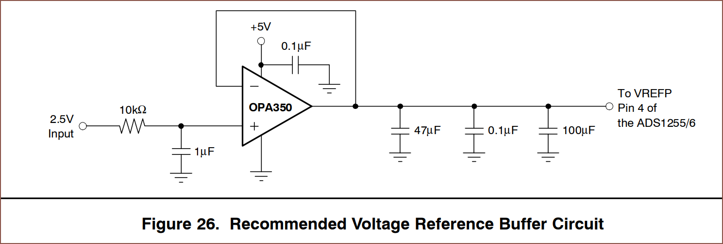
Overall, there's something like 12 components I need to also allocate PCB space for to even use this chip. I could always put this on the connector PCB, but I'm not sure if it's a good idea having a reference voltage trace spanning across the entire device.
Moving on, it turns out that the M08 and M06 share the same packages and pins, just that the latter (on the right) has 4 more NC pins.
I'm not sure why Ti made seperate datasheets for all the chips in the ADS131M0x range. It's also a bit painful that they said it's "optimized for cost sensitive applications" when it's easily the most expensive chip:

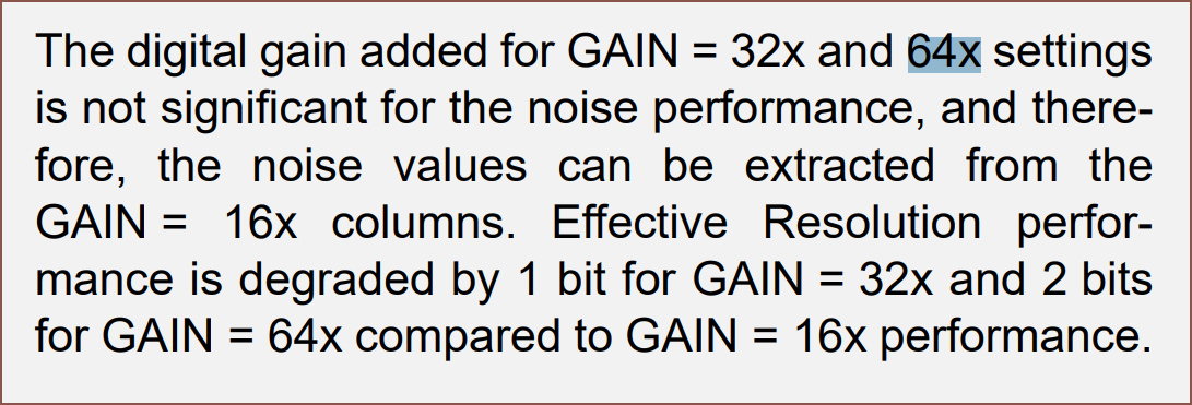
Anyway, most everything in them are identical and there's something I noticed about the ENOB:
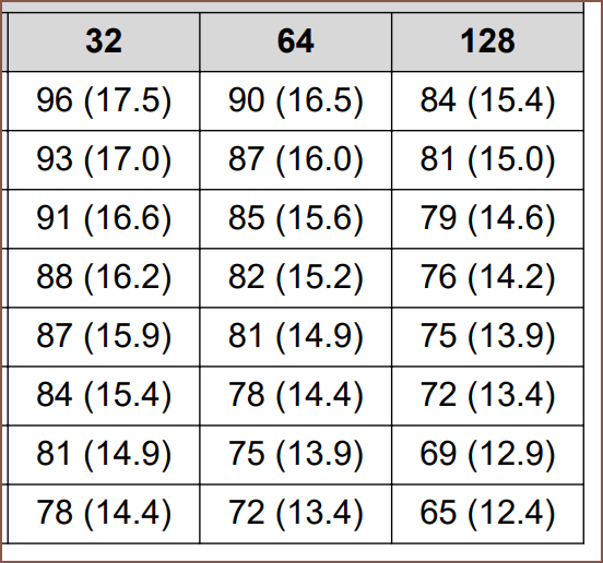
As you can see, PGA=32, 64 and 128 don't exactly do anything. The signal gets doubled, but then you lose 1 bit of precision. It's essentially like just multiplying the values by 2 in software. The FSR at 128 is +/- 9.375mV.
Side tangent: There's also chips that sense voltage and current:
I thought it was quite cool.
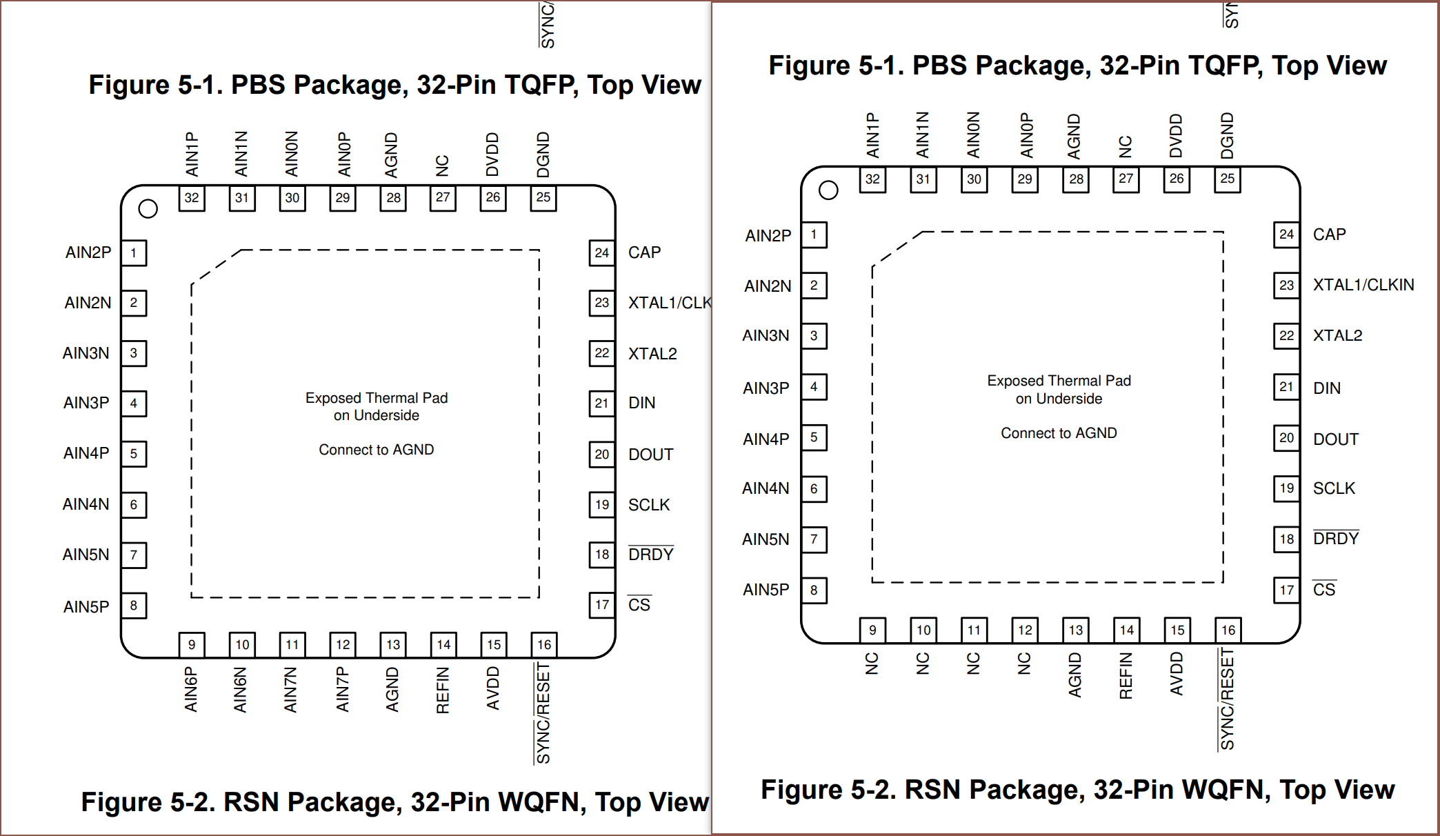
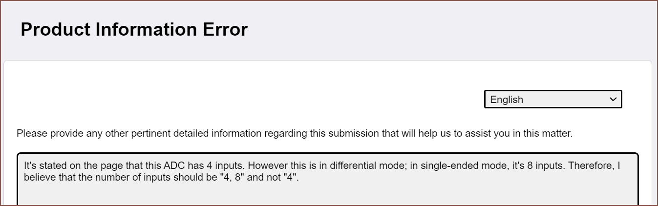
Back to ADCs, I found the reason why I wasn't finding the MCP3564R:
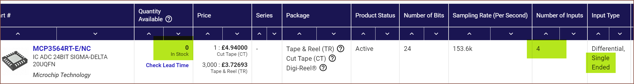
Even though Digikey says it has 4 inputs, it's actually "4, 8" inputs. I've reported it.
[11 Sep: I just got an email back saying they've fixed the whole series and should be reflected on the site shortly.]
Anyway, the datasheet seems to imply that it's specifically designed to be able to multiplex through inputs without settling times. The ENOB values for 32 and 64 have also been omitted due to the 1-entire-bit reduction I mentioned.
This chip has enough speed to sample 6 channels at 1600SPS whilst still allowing for a full 24 bits of resolution:
I think it would make sense to get 5 inputs at 1600SPS and then scan other inputs for diagnostics information, such as the solar cell voltage or ADC temperature.
This chip allows for using 3.3V as the Vref or using an internal 2.4V source, though it seems that it's slightly better to use 3.3V:
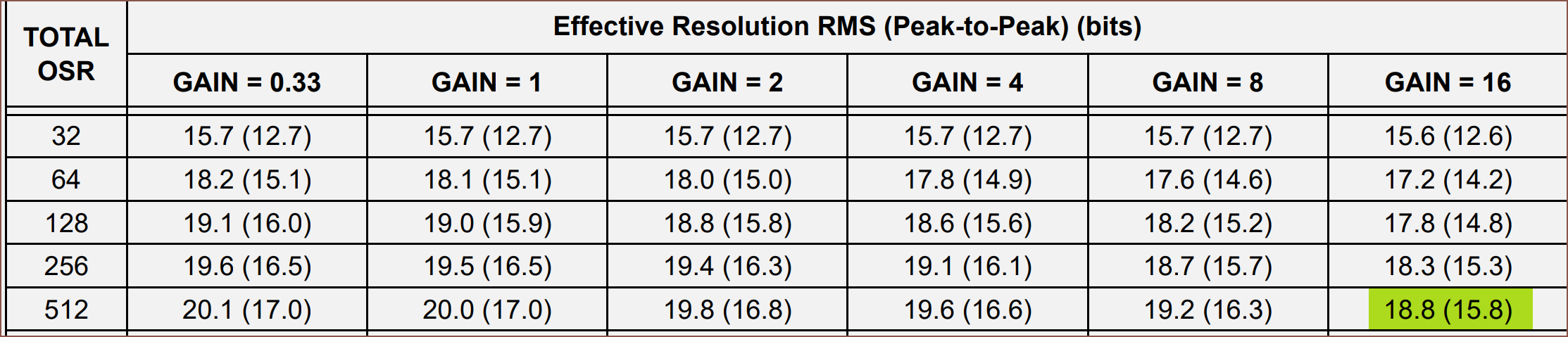
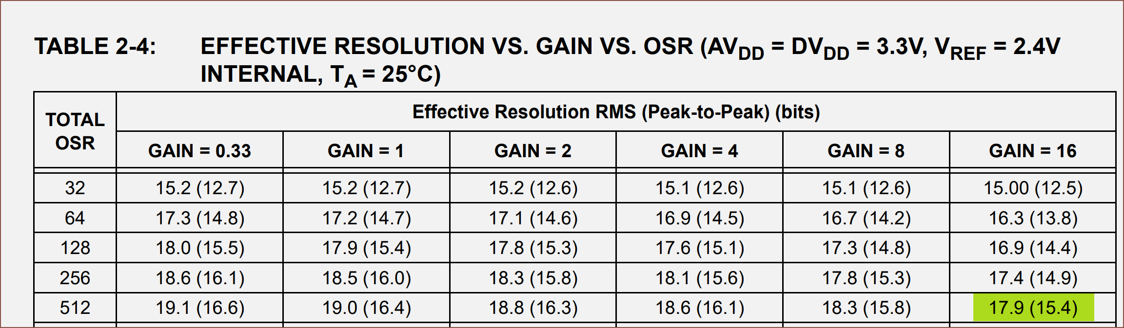
I think their "peak-to-peak" value is equivalent to "noise-free bits".
The smallest FSR is 3.3/64 = 0.05156V = 51.56mV.
Obtainable resolution
With these options known, I can calculate the smallest force I should expect to measure without any noise.
ADS131M08 24-Bit Simultaneous:
    500SPS:
        500g * (9.375 / 3.3) / (2 ^(15-2.7))
        = 0.28168g
    1kSPS:
        500g * (9.375 / 3.3) / (2 ^(14.6-2.7))
        = 0.37168g
    2kSPS:
        500g * (9.375 / 3.3) / (2 ^(14.2-2.7))
        = 0.49044g

MCP3564R 24-Bit Fast Multiplex:
    1.6kSPS, 3.3V reference:
        500g * (51.56 / 3.3) / (2^13.8)
        = 0.54772g
    1.6kSPS, 2.4V internal:
        500g * (37.5 / 3.3) / (2^13.4)
        = 0.52564g

ADS1256 24-Bit Multiplex:
    800 or 400SPS (identical performance):
        500g * (78.125 / 3.3) / (2^14.4)
        = 0.54754g

ADS1262 32-Bit Multiplex:
    800SPS:
        500g * (78.125 / 3.3) / (2^12.5)
        = 2.04348g
    400SPS:
        500g * (78.125 / 3.3) / (2^16)
        = 0.18062g
It seems that any option I pick would be able to get 0.5 grams of precision. Yes, this doesn't sound anywhere near as good as the 0.1g precision scales, but remember that I need this data correct in fractions of a second, not an entire second.
Obviously, correct to the nearest 2 grams isn't going to work for a layout that is broken up into 8 gram layers, but if I can make do with 400SPS, I should expect to improve precision by over a magnitude. It is for this reason that -- PCB area permitting -- I'm probably going to go forward with the 32-Bit ADS1262 ADC.
Conclusion
This concept took 5 days to research and 6.75 hours to write out this log. The good news though is that Tetrinsic would now potentially be
- more visually and dimensionally customizable (due to the 3D printed belt)
- coggless
- cheaper
- self-sterilizing
- more tolerant on finger misalignment (since it's now a wide 10mm belt instead of the valley created between 2 ball-chains)
- more resilient to part sourcing issues
- better in terms of active-length to footprint-length ratio
- less software-complex since I don't need to communicate between 5 microcontrollers
- lower power since I don't have 5 microcontrollers that need power
whilst addressing the concerns Me In The Past had about this solution strategy, such as ease-of-manufacture and electronic restoring force.
Discussions
Become a Hackaday.io Member
Create an account to leave a comment. Already have an account? Log In.