 kelvinA
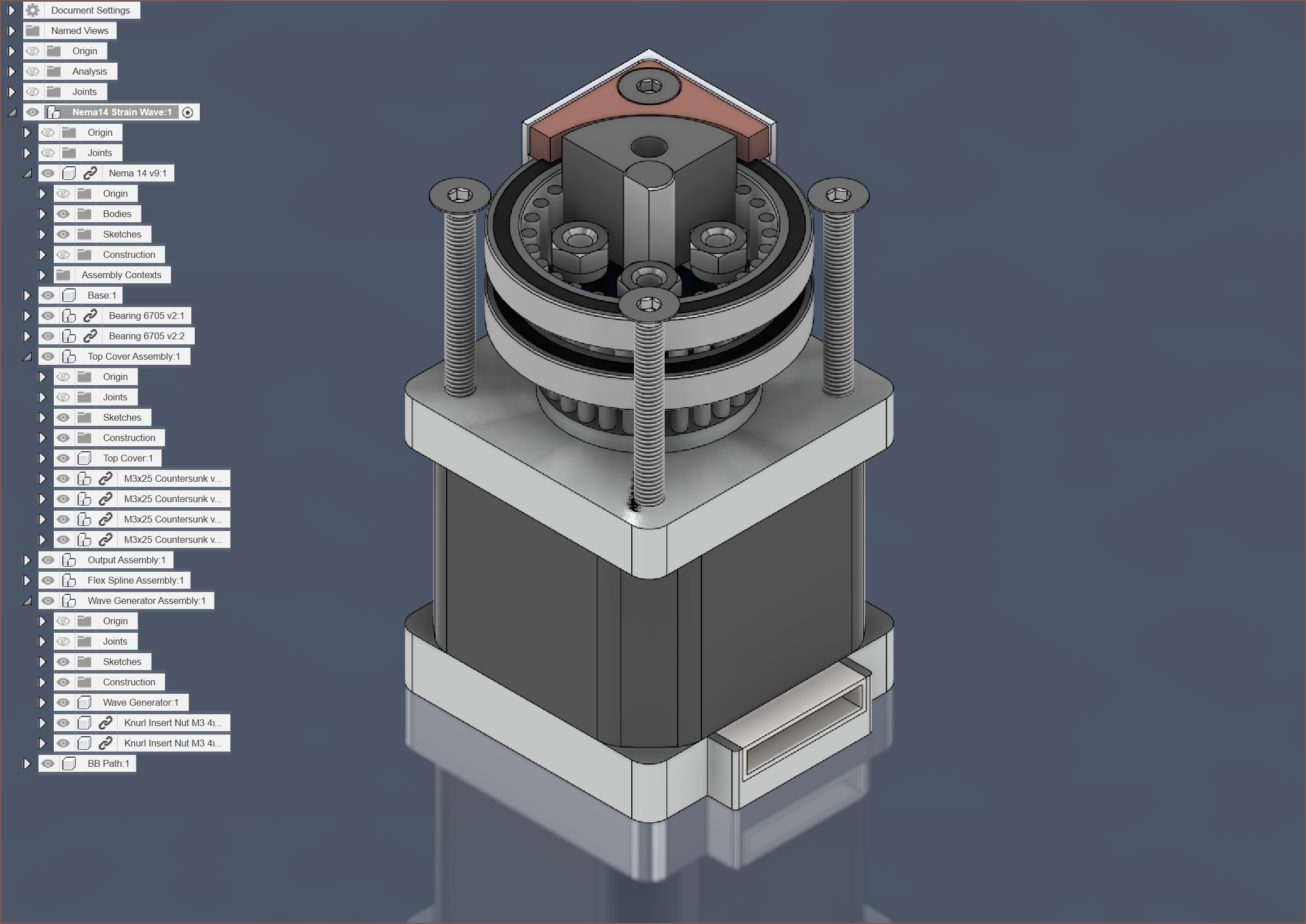
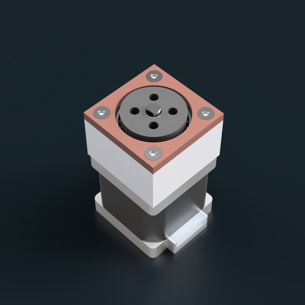
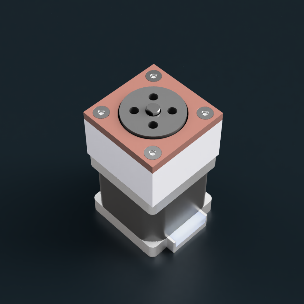
Right so it's been... checks notes... 36 hours since I wrote the log saying I don't know how to progress further. I've now essentially finished modelling the entire thing, and it should be smaller, better, faster and stronger than the previous harmonic drive I designed but never tried out. I've got more confidence in this one, which is now only a compact 35*35*24mm.
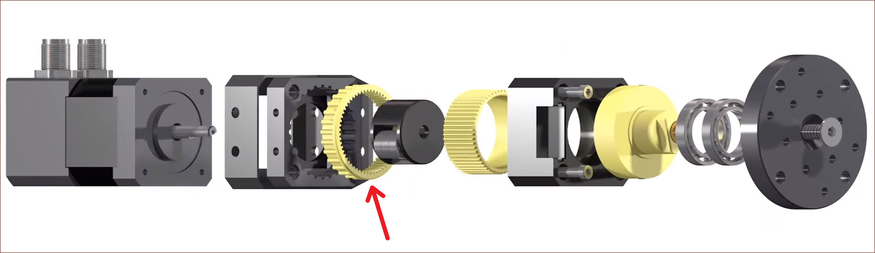
I've gone for the strategy of having a solid output assemby and input flexspline, taking inspiration from this satisfyingly animated video.
Namely, the part marked with the red arrow:
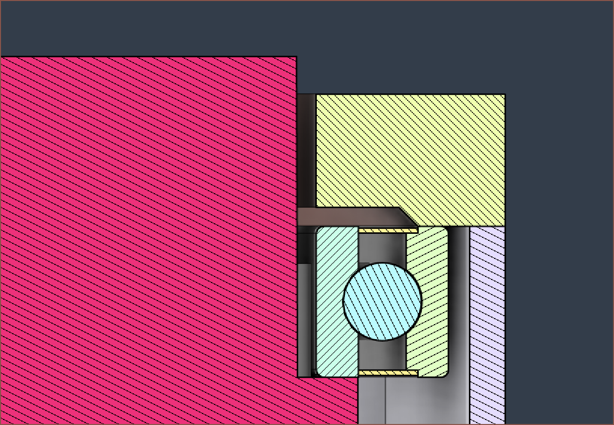
This is a section view of the design:
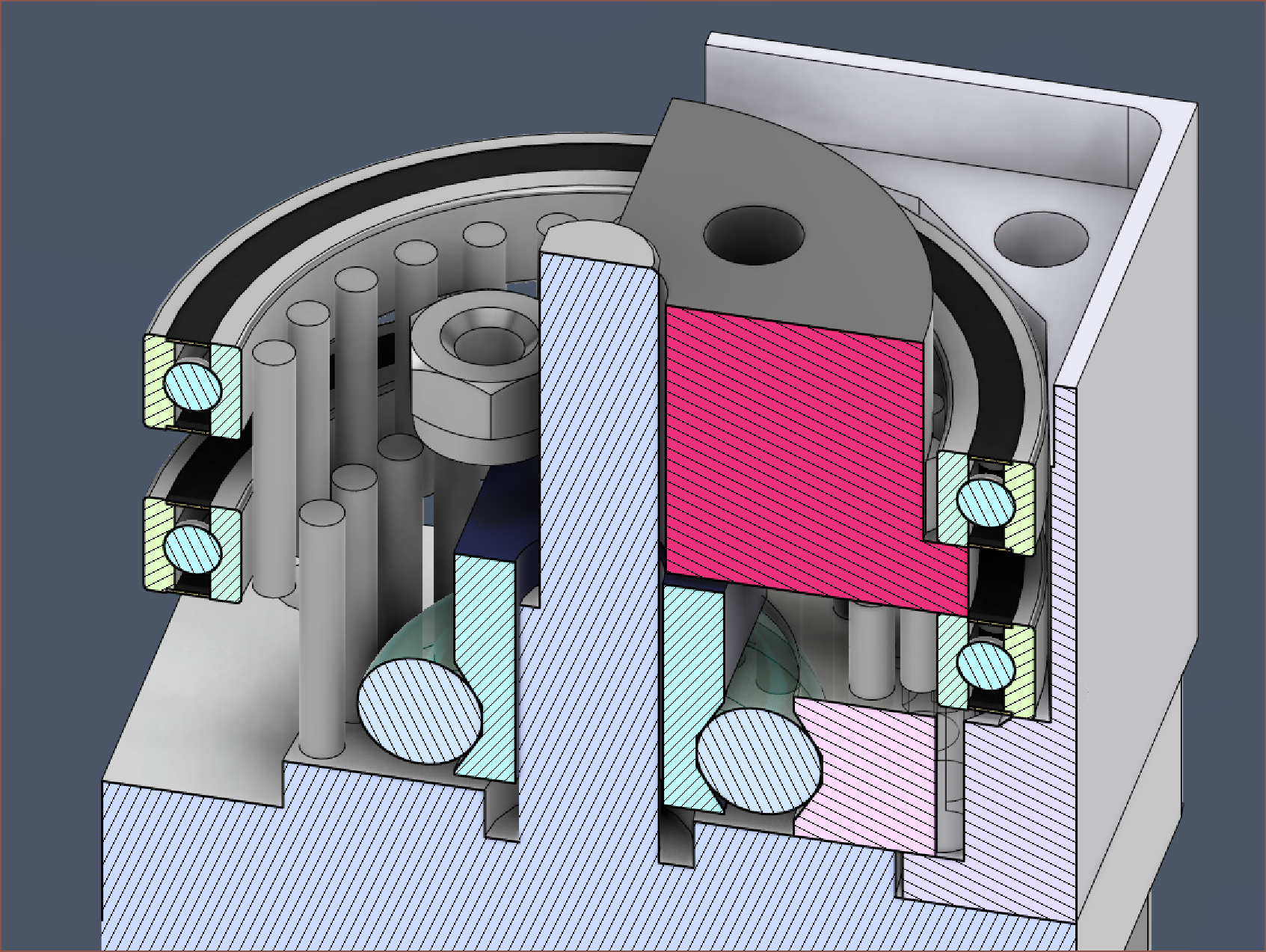
- Transparent Green: 4.5mm Steel BB path
- I wanted to use plastic to reduce the likelihood of raceway damage, but it only comes in 5.95mm sizes.
- Dark Blue: Wave Generator with the choice of 1x or 2x M3x3 heat inserts.
- Transparent: Flexspline
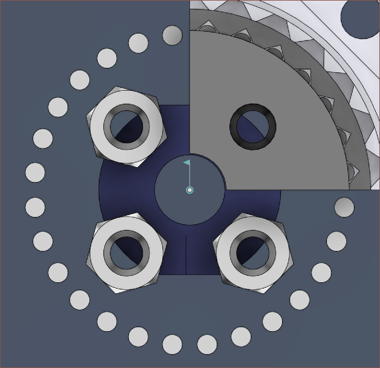
- Dark Grey: Output with 4x M3 self-locking nuts in a 9.5mm*9.5mm square
- White: Enclosure
- Bearings: 2x 6705-2RS 25*37*4mm
- Pins: 54x solid 1.5mm*10mm stainless steel. I found a seller that offered them for 30% less than the steel tubes I found.
- Copper (not shown): Top cover plate + 4x M3*25mm countersunk screws
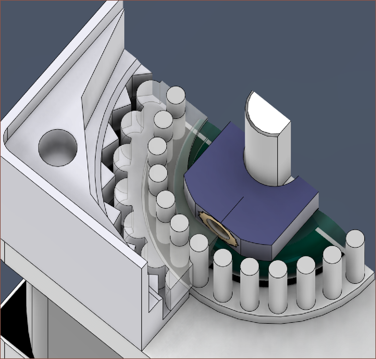
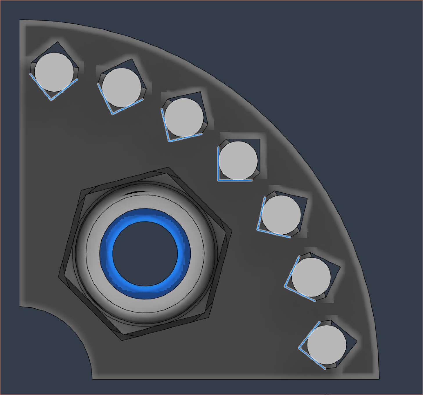
To stop the flexspline from spinning in place, I've gone for 2.5mm cylinders that fit into 80 degree V cutouts:
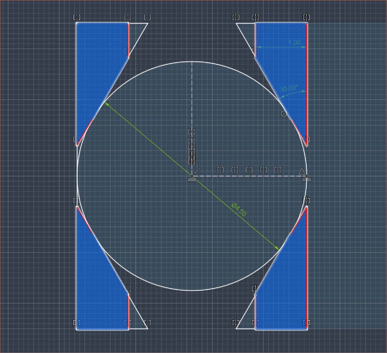
Here is the raceway profile I've used for the flexspline and wave generator, where the ball is in contact at 3 points on each side:
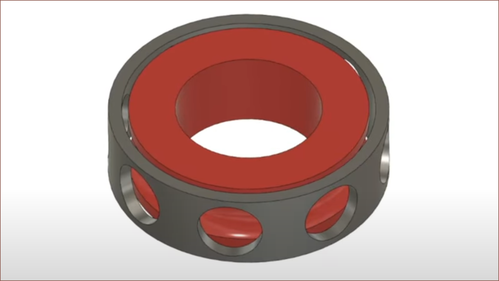
I just need to model the bearing spacer, which reduces both the amount of bearings needed and the friction of the bearing. It looks like the grey component below (click image for source), where the red component in the image would correspond to the wave generator:
Speaking of that wave generator, I'm cutting things close. 4.5mm BBs are cheaper than smaller sizes like 3mm, so I looked to see if I could get away with it. The wave generator is only a 1.2mm wall at it's thinnest cross section. Hopefully, the 5mm motor shaft will reinforce this part.
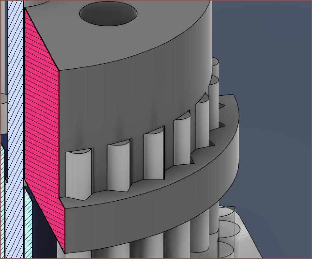
The pins also act as a precise metal-on-metal contact between the output and the bearings. Unlike the flexspline that uses circular pin holes for a tight fit, the output uses more V's (these are 90 degrees) so that the pins shouldn't be overconstrained:
I'm using self-locking M3's because I've got the space and all this stuff is moving. shaking and vibrating so it's probably for the best.
In terms of pricing, all the metal components total to £3.69/ea, assuming rates of
- 1500 BBs for £7,
- 700 pins for £16.05*,
- 10 bearings for £6.96*,
- 250 brass inserts for £4.75*,
- 100 M3 self-locking nuts for £5.20,
- 50 M3*3mm grub screws for £0.83*
- and 100 M3*25 countersunk screws for £6.37.
- (*used [£price]* 1.2 in the calculation to reflect the 20% VAT charge of AliExpress imports)
It is also assumed that only 6 BBs and 1 heat insert + grub is used, thought I can imagine 2 would be needed to prevent vibrations due to the centre of mass of the wave generator. I think being able to keep the original idea of metal-on-metal contact for the flexspline-to-output transfer is the best part of this proposed solution, but the steel pins are the largest contributors to the cost. Add in the printed parts, and it's probably a £4/ea gearbox. Sure it's a 35*35*24mm, metal contact gearbox, but I was hoping for something like £2-2.50, with £3 as a stretch. I need 5 of these per Tile, so that means that I'm already at £37.50/ea from just the P2.5 LED Display and gearboxes (though, the seller has a near identical, non-bevelled frame display for £5 less, so I wonder if I could get even more savings by asking to buy a frameless version). The motors and S6609 stepper drivers are another £20.35 to the BOM/ea.
It doesn't look like 16pcs for £1000 is going to materialise (£62.50/ea). £75/ea maybe?
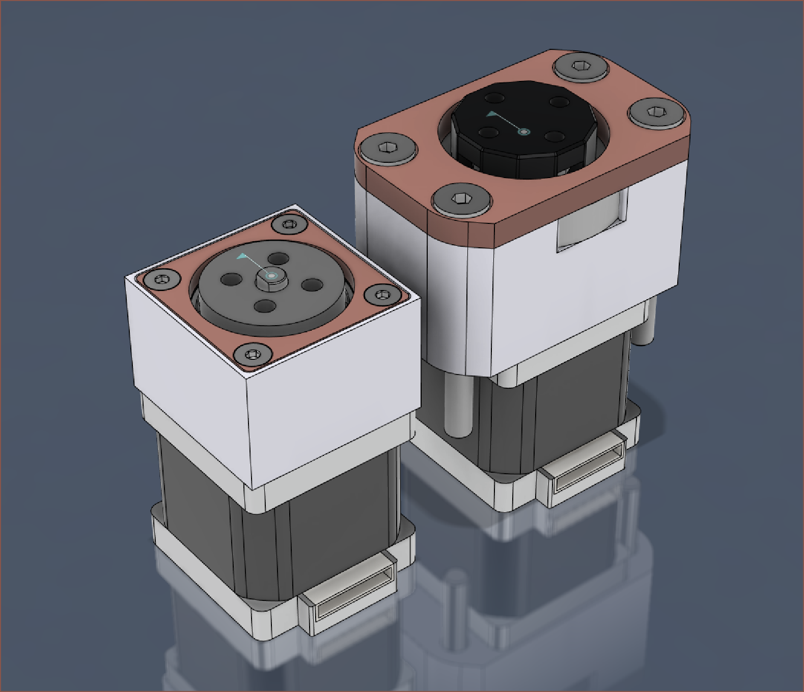
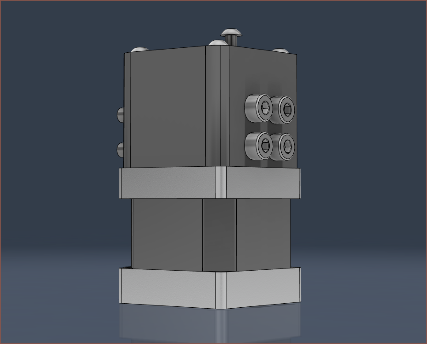
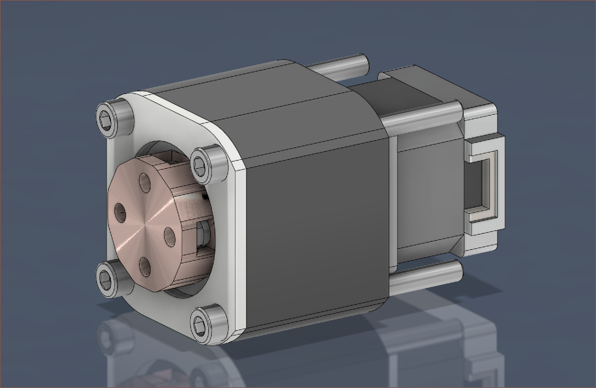
Anyway, here's some more images:
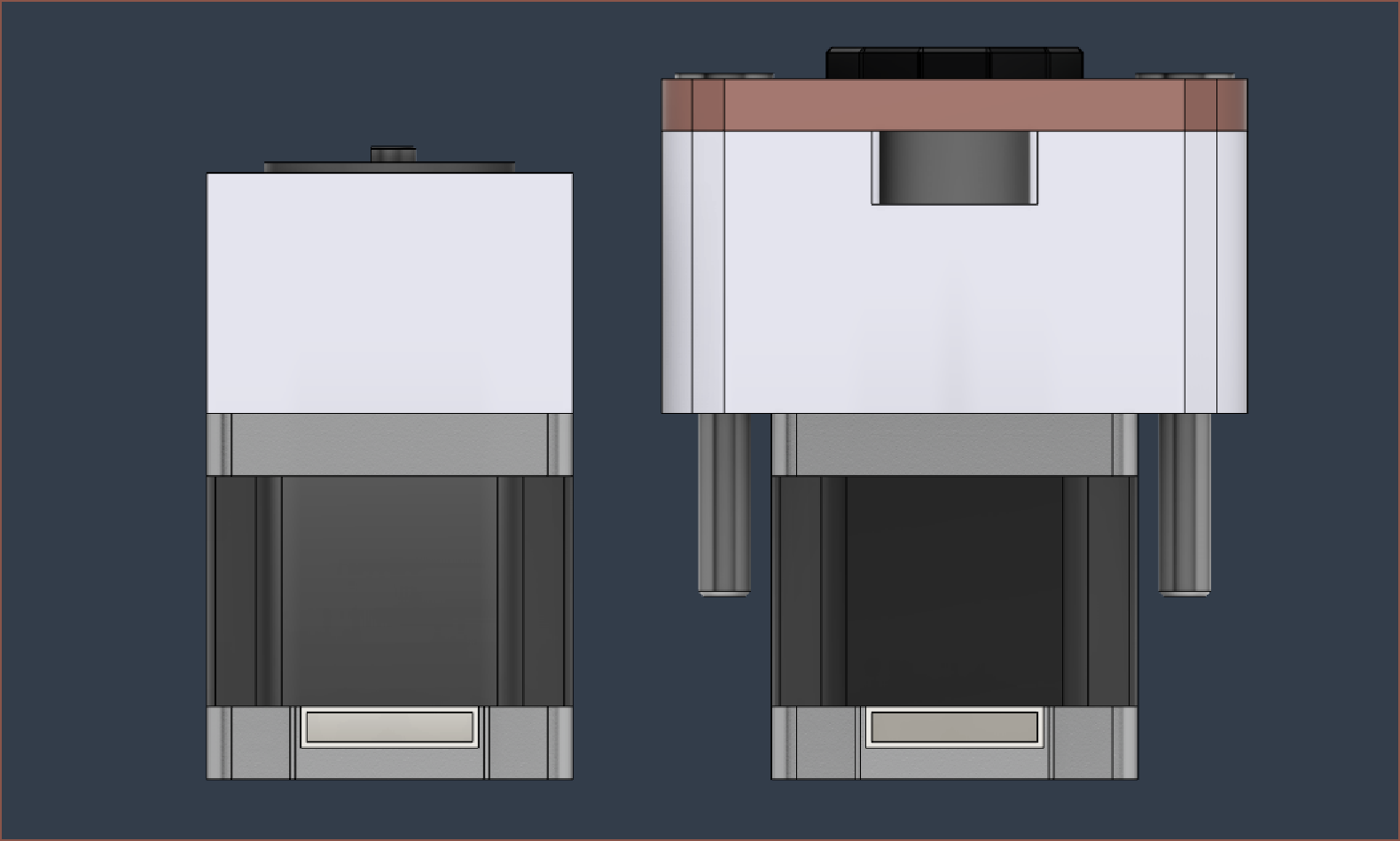
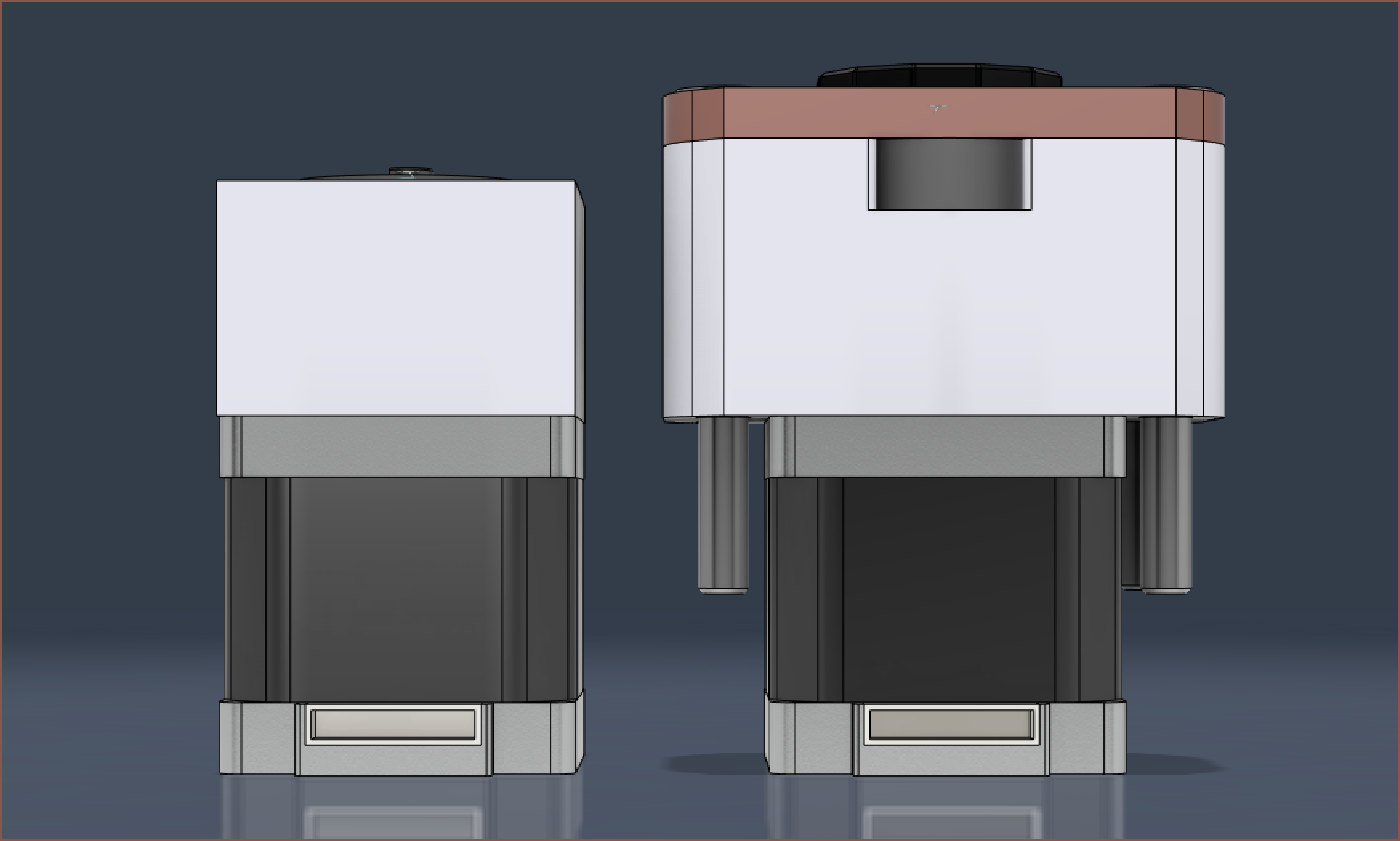
I'm most likely going to go for a similar top cover design as the previous verson though. There's just so much empty white space and it probably increases print time for the enclosure more than it decreases print time for the top cover. It also is one less thing to go wrong, as the top cover no longer would need to perfectly fit into the enclosure. On the other hand, the edges of the gearbox are no longer smooth, and there could be positional errors with the top cover meaning that it slightly sticks out. Well, here's what the variation looks like anyway:
For mounting, I'm thinking of clamping the Nema 14 similar to how it's done on CNCs like the 3018. I could also do a strategy that Me-In-Jan-2021 was going to try, where bolts go through a block and narrowly miss the 5mm shaft. It turns out that 9.5mm square is enough space to do it, just like the output mounting holes, so I should remember this for a possible strategy for Axis 5:
While I'm here, might as well take a trip down memory lane. The above is v47 of the design, and this was going to be a redesign of v35:
This was 52*52*48.5mm large and was a 16:1 reduction.
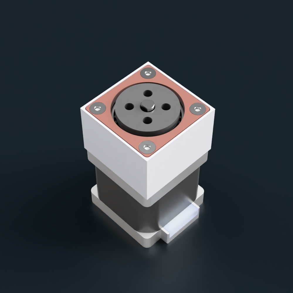
Back to the current version, I could probably bring in the top cover hole to further prevent dirt from entering the drive. It's still a 0.5mm gap so it's not like it's become dustproof or anything, but it should (in theory) reduce the likelihood of dust entering.
The bearings themselves are 2RS so should have good dust resistance, and the only way dust can get to the bottom half of the system is through the small gaps around the pins. I'll admit, it doesn't look as powerful / high tech with a smaller gap, but generic-ly simple as if it was just a basic mock-up without any internal geometry:
It's probably for the best, though.
[30 May: Edit 1] I've just edited the wave generator to also block the M3 nuts from falling down during assembly.
I also watched the below video and now looking into life cycle testing, such as this research paper on accelerated life testing.
Discussions
Become a Hackaday.io Member
Create an account to leave a comment. Already have an account? Log In.