 kelvinA
The pins are the most expensive part of the harmonic drive and if I'm going for 16 Tiles, I need 4320 of them, so I got to looking if I could find them cheaper. I found this:
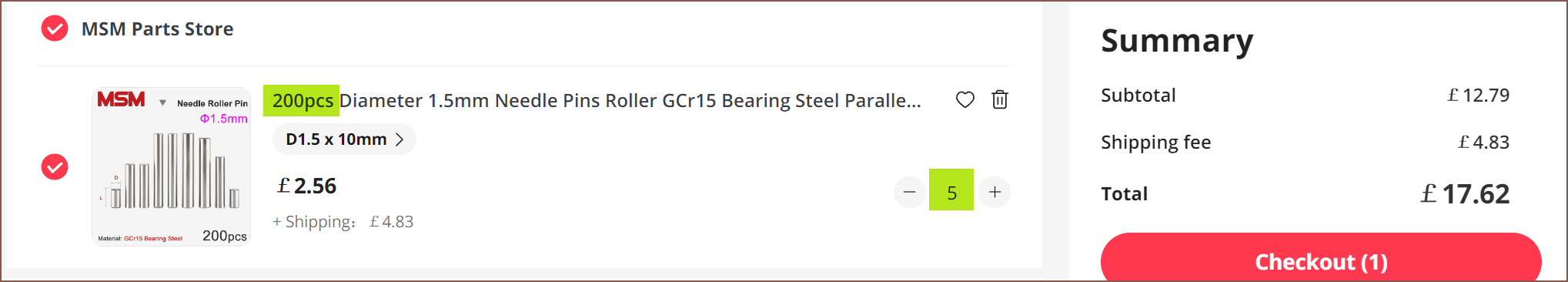
These are needle-roller-bearing pins that have a diameter accuracy of +0/-0.01mm. This seller also has any integer length from 3 - 20mm, so if I need a certain size for the gearbox, I can have it. I just would like to either keep the same size for all of them or, if I must use two lengths, the actual lengths are noticably different. I don't want to be trying to discern the difference of hundreds of 9mm and 11mm pins.
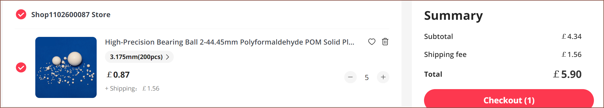
Running mental life-cycle simulations, that wave generator + steel BB proposed solution was still failing and I knew I had to change it out. Conviniently, while I was out searching for the pins above, I found out that you can actually get ball bearings in POM. In another listing, their balls are advertised to have a +/- 0.01mm tolerance and that they're self-lubricating.
There's probably a reason why V-Slot 3D printers, even the high-end ones, don't use metal wheels, and I heard that it's because they have the potential to damage aluminum extrusions. A small, 3D printed part has an even lower chance of survival.
Now that the ball is down from 4.5mm to 3.175mm, I wanted to reduce the height by 1mm. I also found out that the Nema14's I modelled were actually 2mm longer than the real world ones.
Anyway, the only way to do that was to reduce the distance between the bearings to 2mm. It was for the best, though, since that lip for the output is only held by 28x 0.8mm walls (reinforced by the pins) and so a taller lip could buckle easier. I'm also not expecting extreme forces to be pushing or pulling on the output, and axial loads are transfered to the pins. Now, the pin rests on the entire 4mm of the top bearing (instead of 3mm previously), further distributing the load on the output printed part. The minimum thickness of the wave generator is also thicker now.
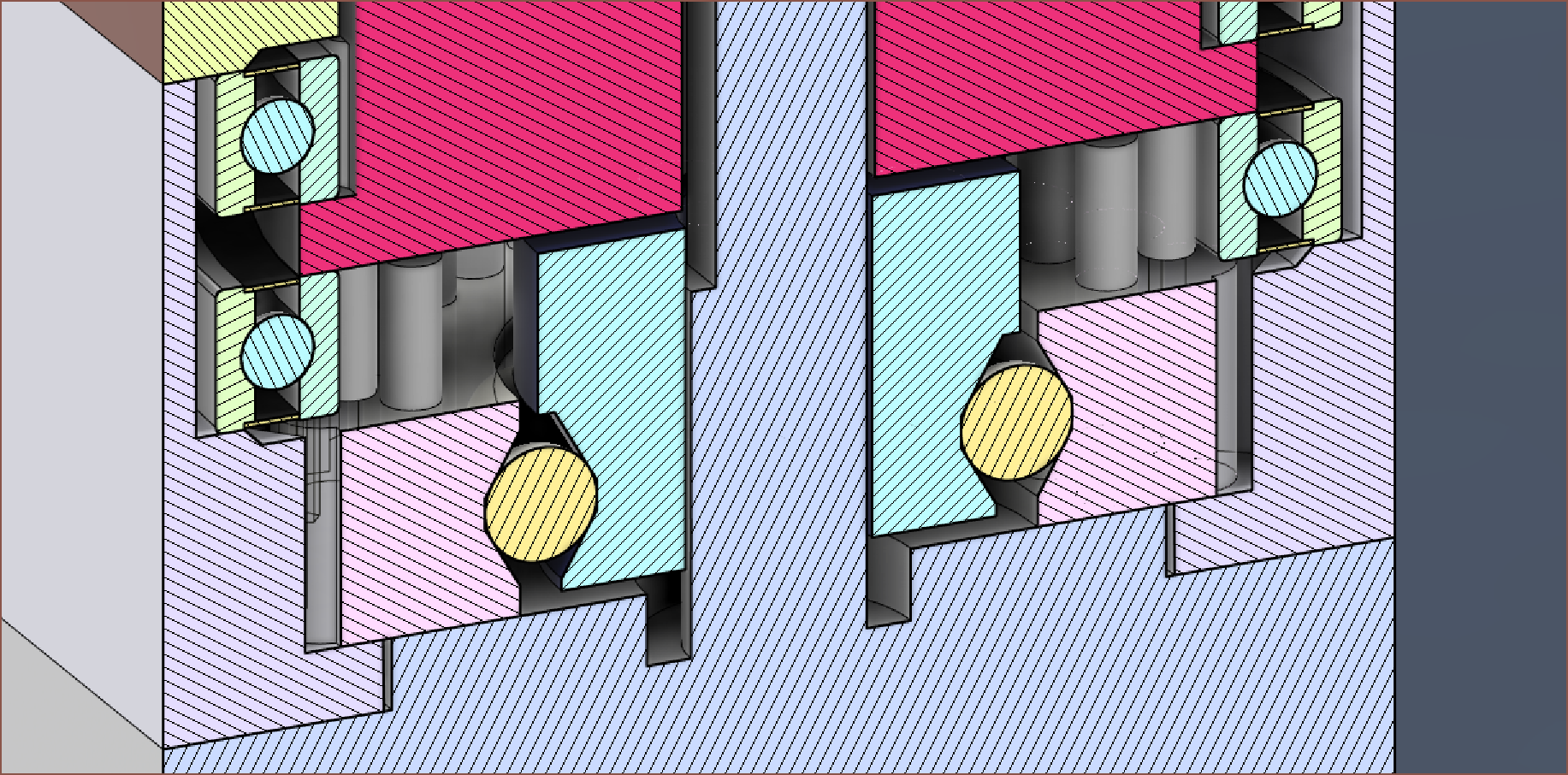
I've also modelled the actual balls, and it's looking like 8-10 with a cage or 12 balls without will fit. I'm also wondering if I should remove the brass inserts and instead tap in the screws for the wave generator. Looking at the videos below, probably not unless I've done some actual testing.
I wanted to see what others were doing about this, and so I started looking at other 3D printed harmonic gearboxes and found these:
- Used dual screws to hold the wave generator on the shaft.
- The wave generator slipping on the motor shaft was the main point of failure. It could be seen that he tried a square nut first that broke the pocket it was in, but after that he was just doing "some changes" to improve it and I couldn't see what.
- The flexspline delaminated. I shouldn't need to worry about that since I'm using "bearing steel" pins.
- At max force failure, the flexspline split in half.
Instead of removing the brass inserts, I'm going to double trouble and use 4 of them:
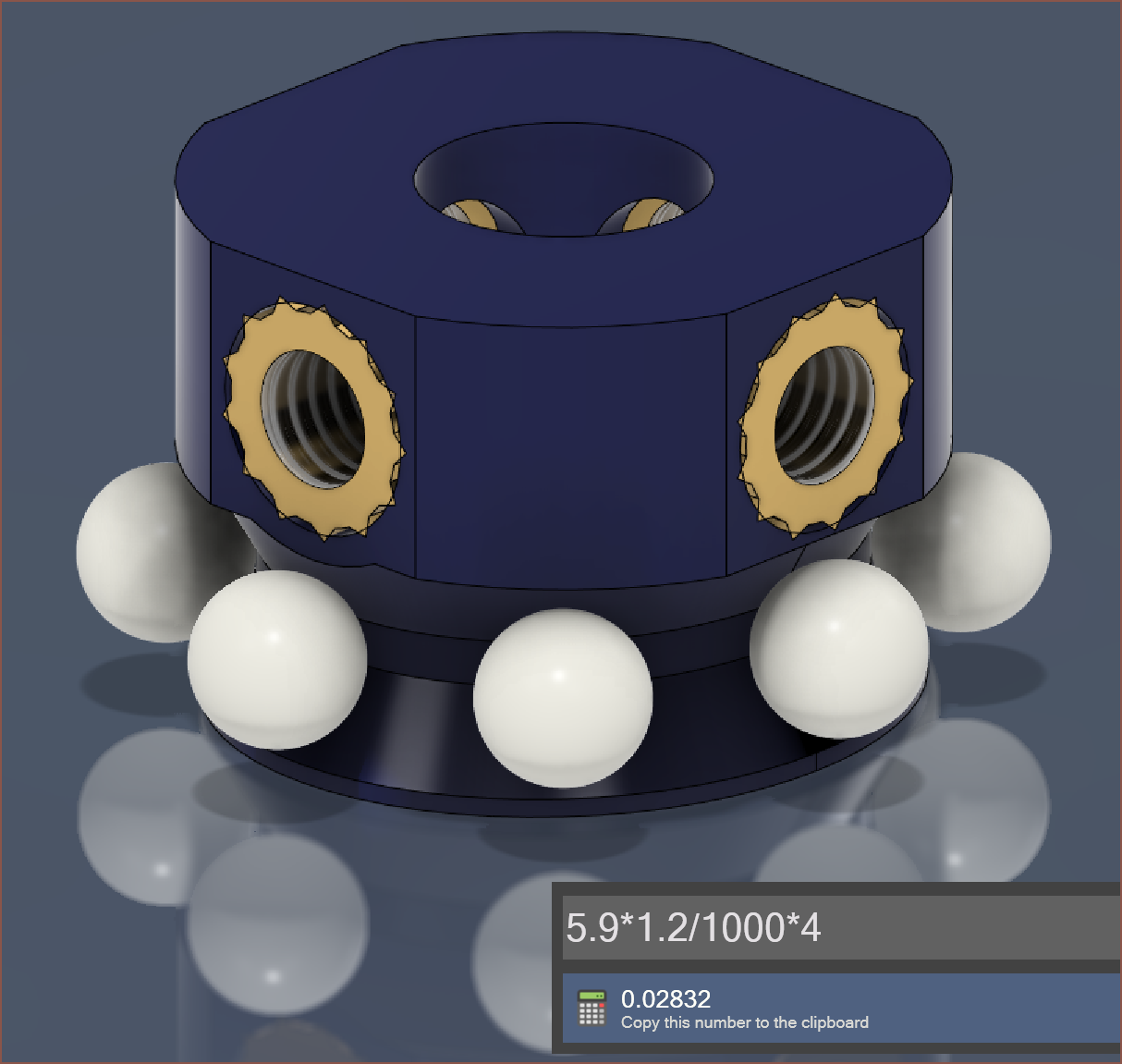 Speaking of 4, I think I'm going to pass on the cage and instead use 12 balls. The difference would be 3p, and I'd expect that a 3D printed cage would cost more. Additionally, more balls means that the loads exerted on the wave generator are more distributed and would better imprint the eliptical shape onto the flexspline.
Discussions
Become a Hackaday.io Member
Create an account to leave a comment. Already have an account? Log In.