kelvinA
Navigation
The title tag system is explained here, and the table is updated when a change occurs. This project also has a tag for each of the printers. Notable logs have bold L# text.
A log of upgrading / repairing my (non-SecSavr) 3D printers.
Already have an account? Log in.
To make the experience fit your profile, pick a username and tell us what interests you.
The title tag system is explained here, and the table is updated when a change occurs. This project also has a tag for each of the printers. Notable logs have bold L# text.
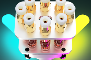
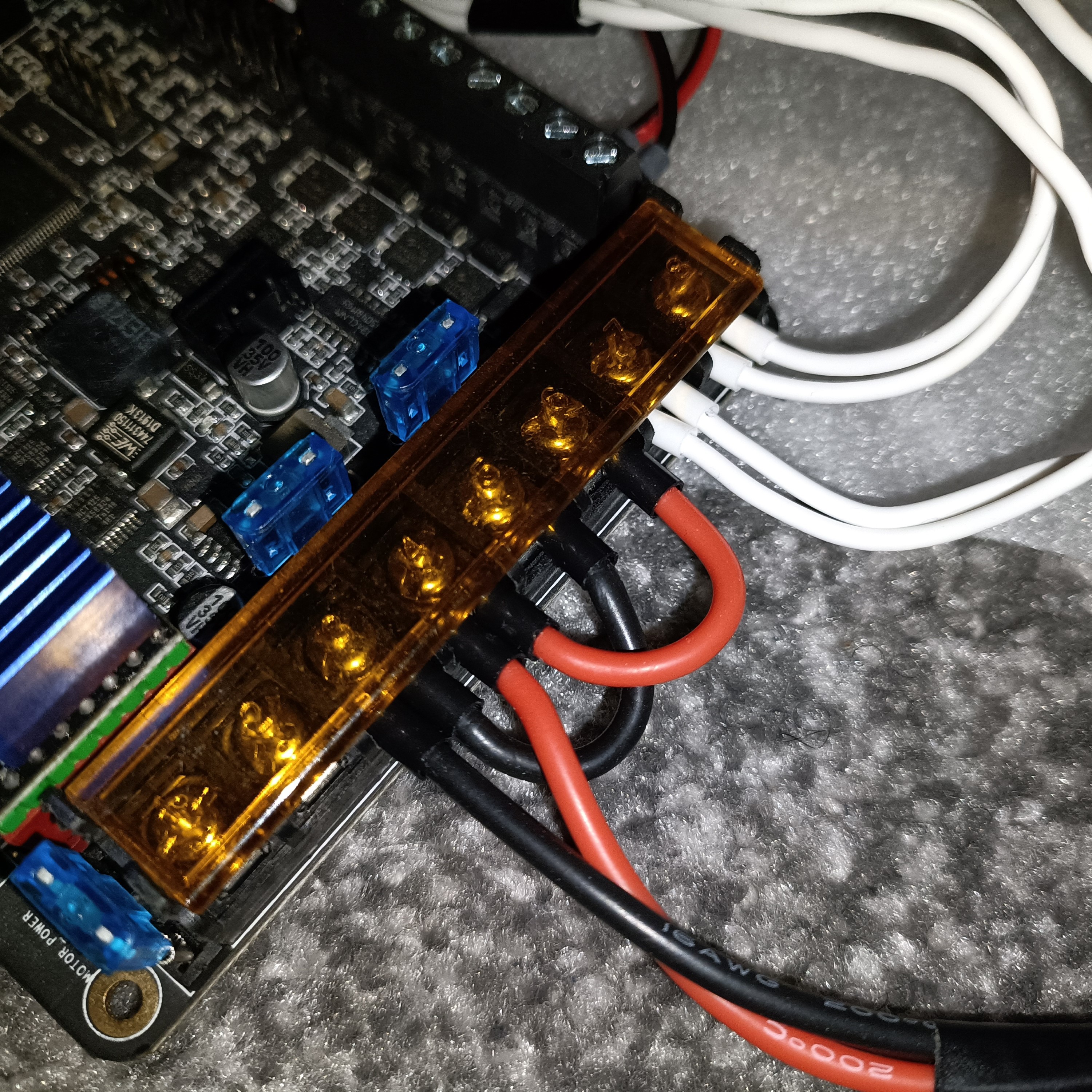
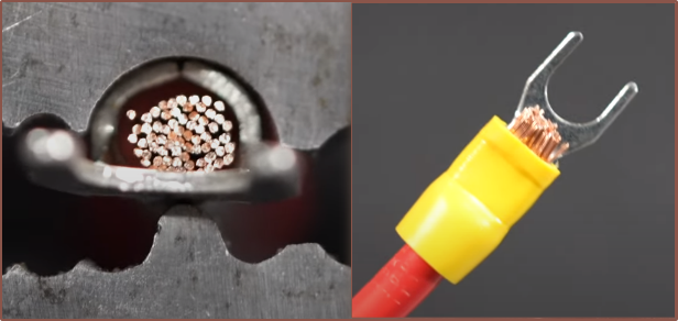
I ordered some cool wire block terminals because the terminals on the PSU looked too small to be able to fit 2 ferrules into them. Other than having to double up the 20AWG silicone wire for the live bed wire, they were no problems with them. They're quite easy to use; just strip the wire, insert and close the lever.
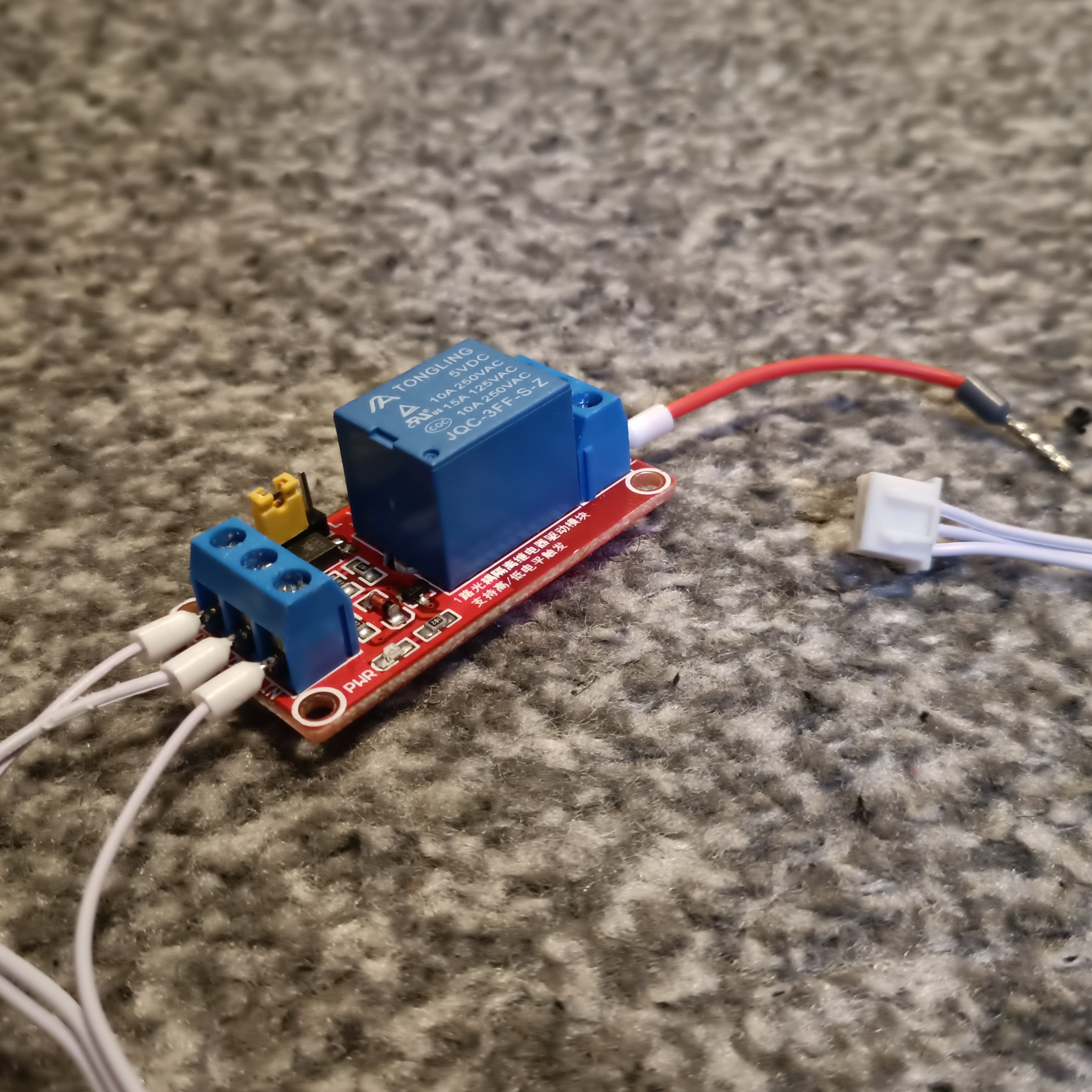
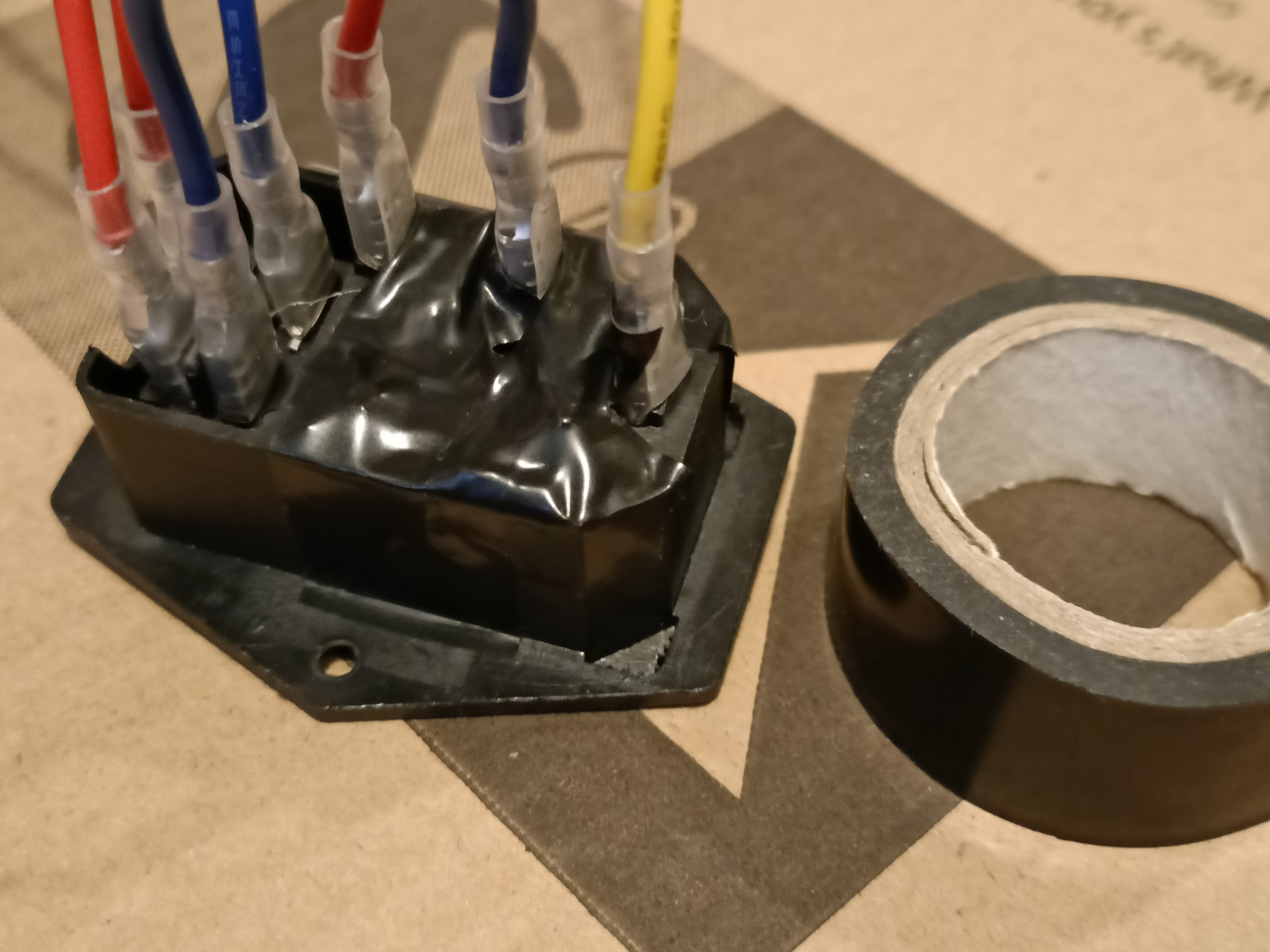
I failed to integrate a mechanical relay into the AC bed circuit. The idea was that, in the event of a fault, AC power to the SSR can be cut. This is because I've heard that SSRs can fail in a way that keeps power permanently on.
The wires I tried to use were fairly thin and my smallest size of ferulles (white) were not small enough so I had to fold over the bare wire and then crimp multiple times. Additionally, these blue terminal blocks are awful as the white ferulles only barely fit and one of the screws had quite a bit of friction. I'd recommend finding a relay with green blocks:
In any case, the 5V relay, in either the high or low trigger mode, didn't seem to close the connection. I'm not sure if I'm missing anything in the Marlin PSU-on feature settings, but I think the reason is hardware related as the signal pin uses 3V3.
I cut off the dupont and crimped XH onto the wire that was already there, and all seemed fine other than I was fluctuating between 21 and 23C degrees. I thought it was a poor crimp job so I tried again (and one of the crimps literally came undone just trying to get the wires out of the housing). Second attempt had no thermistor reading whatsoever so the 3rd time I just soldered on a wire with a pre-existing XH termination. Still got the fluctuations, just at a slightly higher frequency. It'll be something like 24->23->22->24->23... at a frequency of 0.2Hz.
I should finally be good to finally answer the main question: Does the #Coaxial8or [gd0144] work as intended? All CR600S related systems seem operational now.
With the #Coaxial8or [gd0144] installed, I've gone to the limits (of the printer) to get this information.
// The size of the printable area
#define X_BED_SIZE 308
#define Y_BED_SIZE X_BED_SIZE

// Travel limits
#define X_MIN_POS 0
#define Y_MIN_POS -9
#define Z_MIN_POS 0
#define X_MAX_POS X_BED_SIZE
#define Y_MAX_POS Y_BED_SIZE
#define Z_MAX_POS 328
308 x 308mm is where the nozzle is just inside the edge of the bed for my printer. Due to the bowden tubes for the coaxial8or, I've only gone up to 328mm. It seems that I can comfortably do something like 305 x 305 x 325mm, which is essentially a 12 inch cube with Z height to spare; I'm satisfied with that. I still get to use the full advertised XY bed size for the CR-10 and I don't think I've ever had a single print even 250mm high, let alone the 400mm that a stock CR-10 supports. Like I've said in this Coaxial8or R1 log, I've tried hard to preseve my XY limits, even going as far as the #Revolving Hotend [gd0012] so that I didn't lose any to XY nozzle offsets.
I should mention that I've got a custom Y tensioner installed, which allows an extra 10mm or so, hence the negative Y_MIN_POS. It would likely be decreased to -6 if one was to install the slimmened Coaxial8or R1.
//#define DEFAULT_AXIS_STEPS_PER_UNIT   { 320, 320, 1600, 1675 }  // 64 microsteps
//#define DEFAULT_AXIS_STEPS_PER_UNIT   { 80, 80, 400, 418.750 }  // 16 microsteps
#define DEFAULT_AXIS_STEPS_PER_UNIT     { 80, 80, 400, 209.375 }  // 16 XYZ, 8 E microsteps
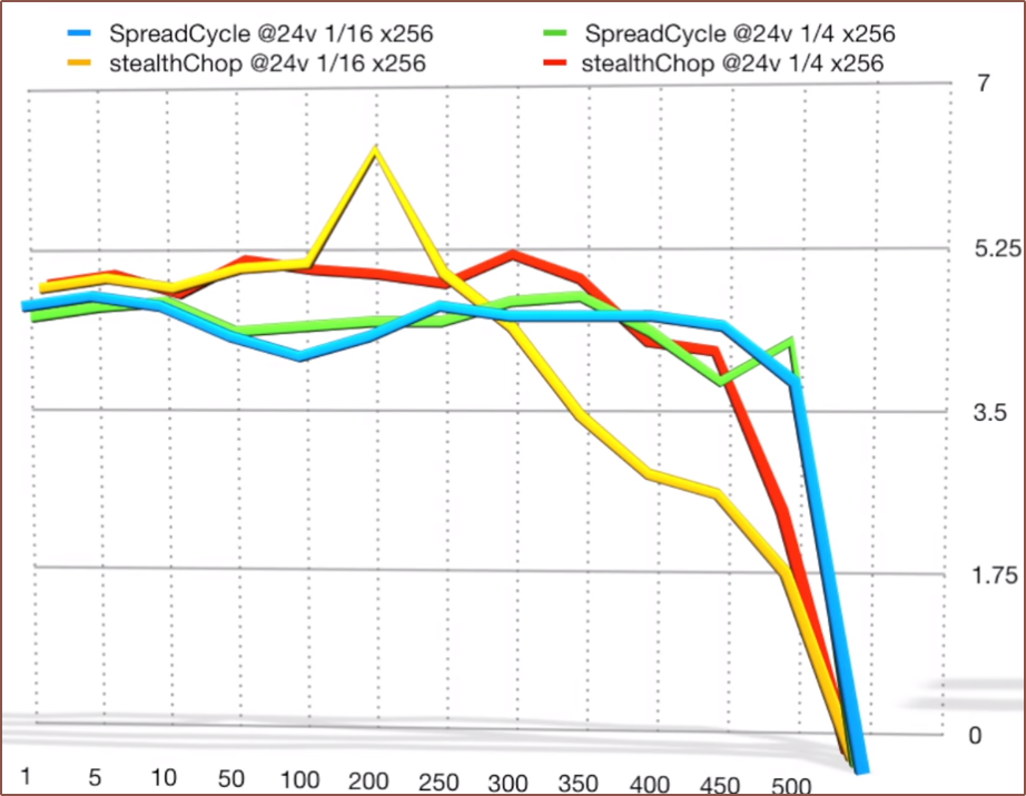
This agrees with my previous go-to value of 418.5mm that I must've calibrated years ago when TriangleLab first came out with their BMG clone and have used it blindly with every BMG clone since. Now I have a more accurate value, obtained by going up to 64 microsteps and no interpolation and getting 99.97mm when expecting 100.00mm. I've then dropped the E to 8 microsteps, mainly because there's eight of them and I don't want to find out that the 180MHz chip on the Octopus Pro can't handle that kind of step rate, but also because of the below graph from this video:
This is for the TMC2208 (not the 2209/2226 I've got) and the lower microsteps were 1/4 not 1/8, but I'm just kind of assuming that the torque curves between StealthChop and SpreadCycle are more similar at 1/8 than 1/16.
Surprisingly, even though the task was simple, it took 3h 20min to actually do the following:
I've used the packaging from the DDE (Dual Drive Extruders from SanBrother) as the testbench, which was a good idea as the PCBs have much more grip.
I haven't yet done the electrical system for the AC heated bed, as right now I've only got one question on my mind: Does the #Coaxial8or [gd0144] actually coaxialate?
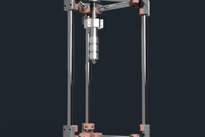
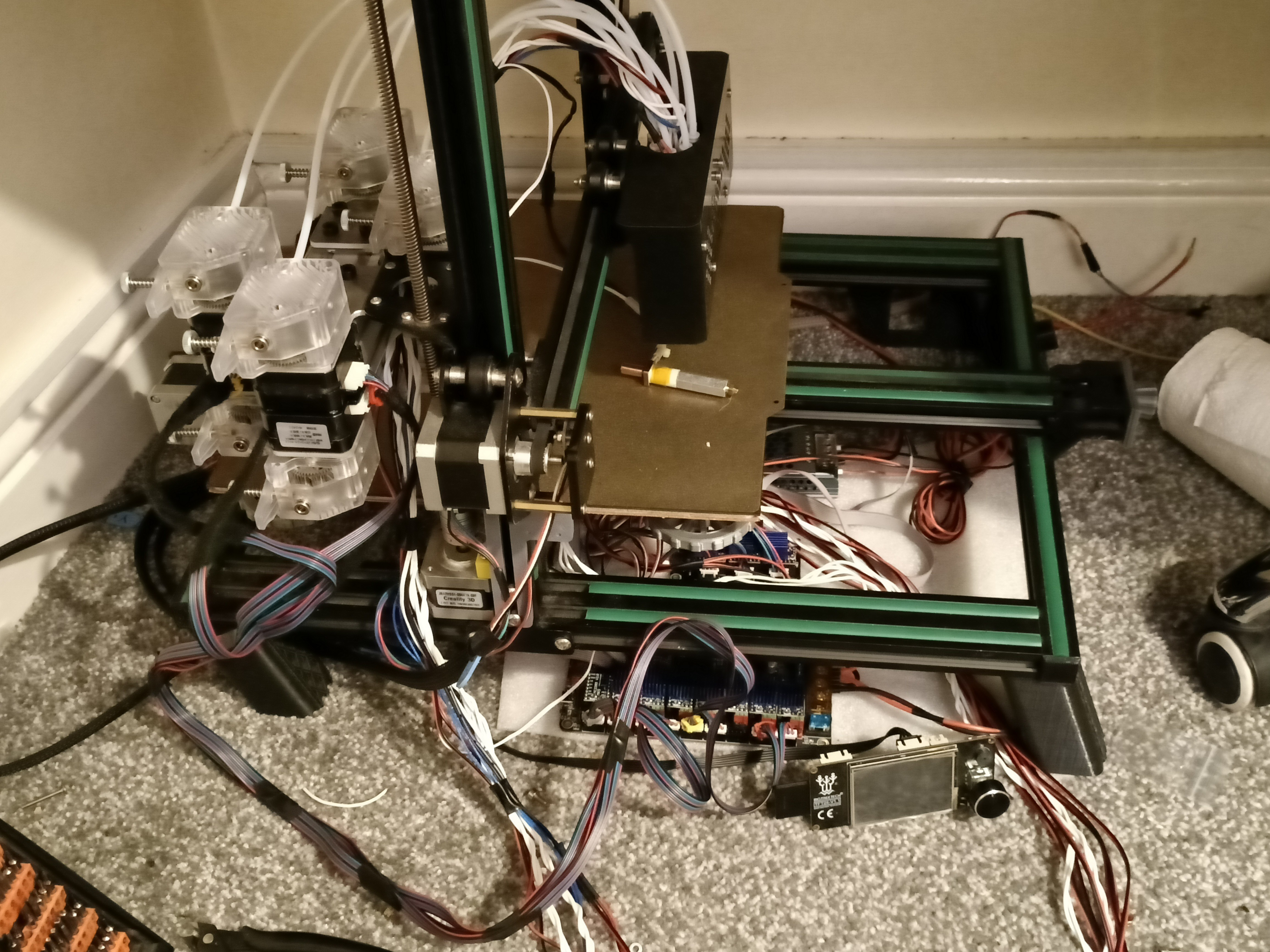
Oh, right. I also had to get an extended Z axis endstop holder printed this morning. You can see it installed in the topmost image.
The Coaxial8or has been installed and now it's time for me to get the new electrical system set up so that I can heat up the CHC Pro and unscrew the heatbreak and nozzle that are both currently attached to it.
If you've been reading those logs, you may remember that my PSU popped a fuse. I didn't know if it was the suspicious PSU itself that's been sitting in the open in a cupboard for years or the shady mains kettle switch socket, so replacements for both have arrived in the mail. I'm partway though the upgrade when writing this intro, and it was the switch socket's fuse that has blown.
I decided to finally look into installing safety related features for the bed before I power the printer back on. I don't think I remembered to mention this anywhere, but when I was working on the CR600S and my arm lightly grazed the edge of the spring steel bed, it felt a lot sharper than it should have. I got a multimeter to it and left ground floating, and I was getting as much as 18VAC, down to 4AC when the bed was powered. My current hypothesis is that the (reverse order) stackup of
is acting like a capacitor.
Unintentional potential differences like this is why earthing bonding wire is needed for things like plumbing. Me In The Past knew that, for safety, I should earth the AC bed when I installed it, but quickly dismissed the idea because I had neither the tools nor any free tapping locations to screw a bonding wire in. It didn't help that I couldn't (and still can't, hence this log) find any strategies for grounding a CR-10 / Ender3 bed (with or without an AC silicone mat installed).
Well a few weeks ago, I came to the simple conclusion to just use one of the 4 M4 tramming bolts that are already there.
To facilitate this upgrade, I've gotten the following:
I've also got silicone bed spacers installed.
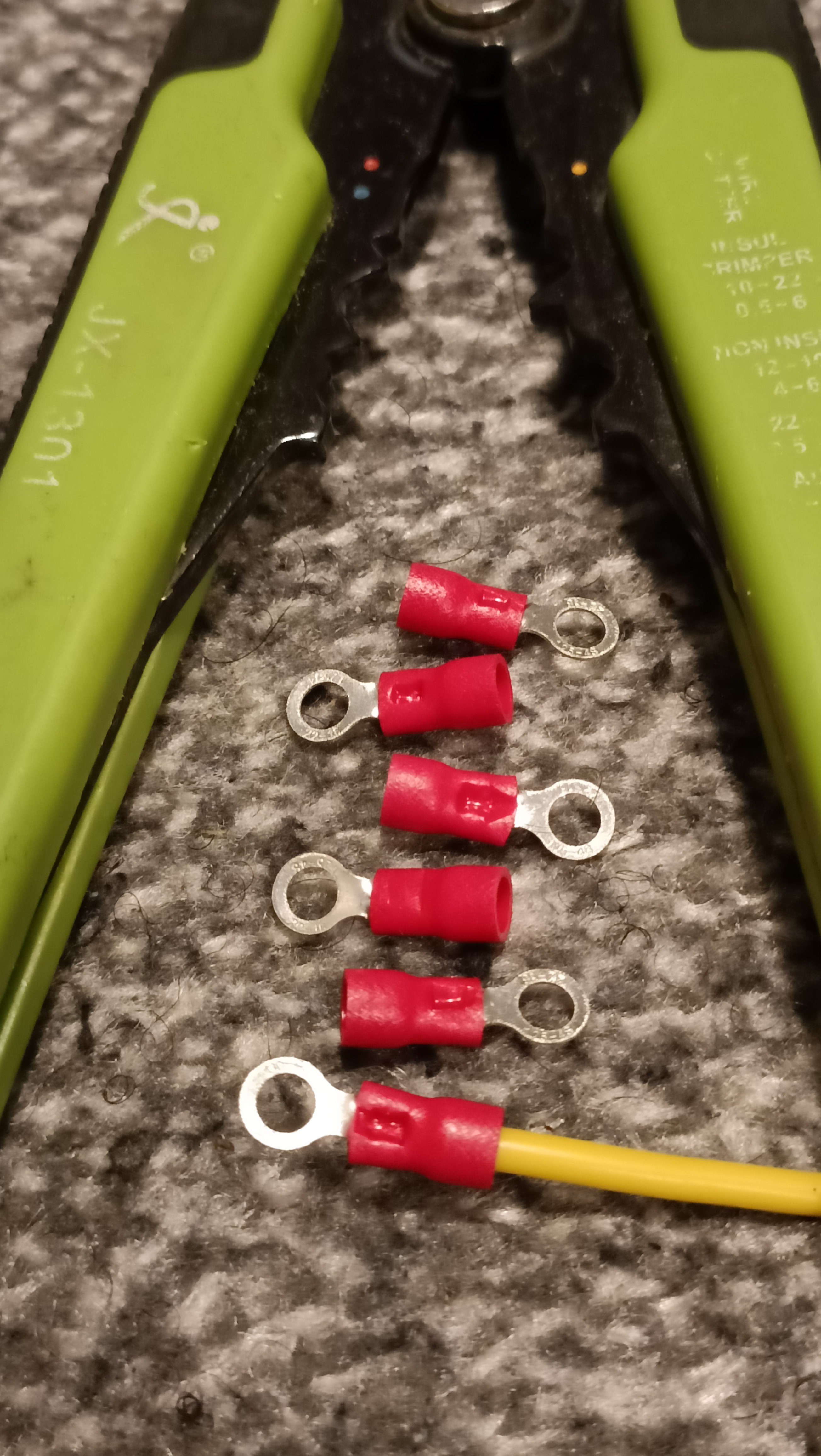
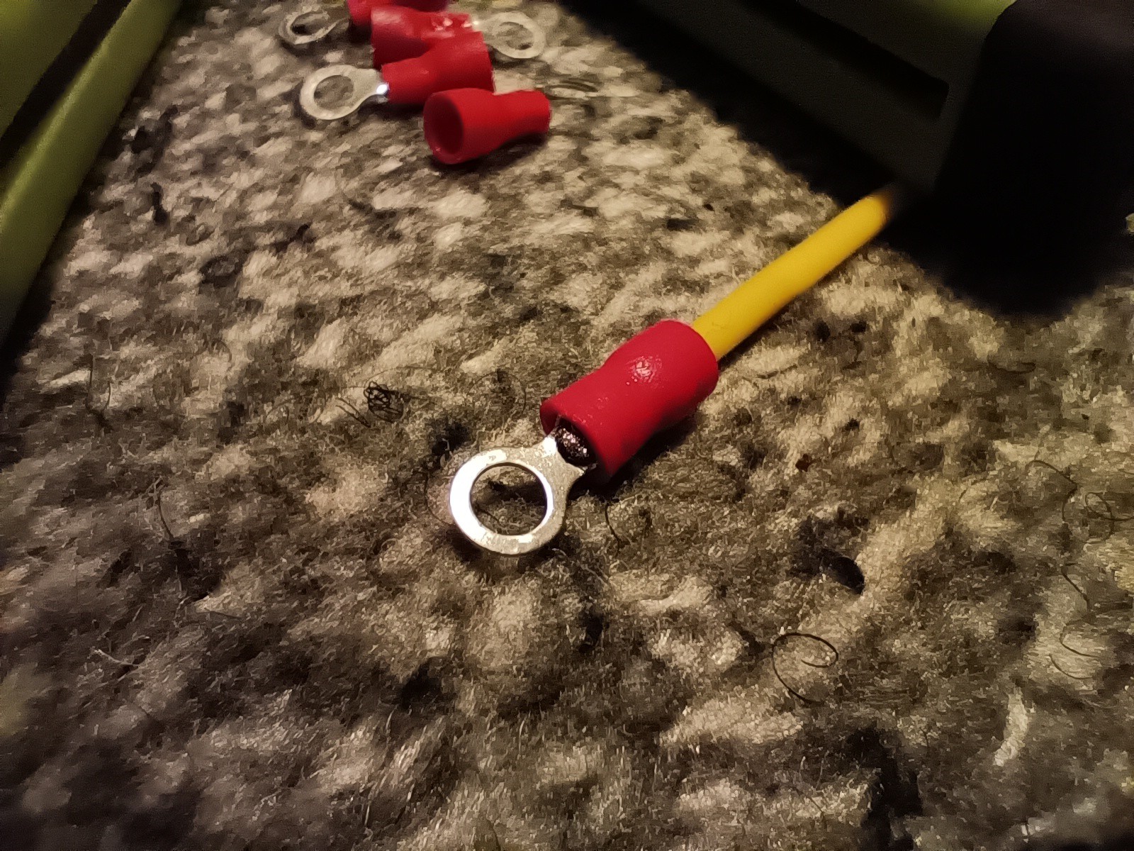
I feel somewhat proud of myself for splurging an extra 20p on the set of 25 of these instead of 10, because it took 6 attempts to get a crimp that was sufficient:
First I had looked up the tips for doing a crimp in the first place, such as crimp orientation and splice length.
I'm using the JX-1301 and I had to strip about 2mm before the minimum helper barrier (approx 5mm from the cutting pincher).
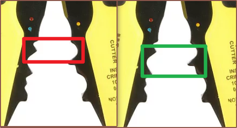
Then I tried a few times using the crimp rectangled in red, before seeing that the one in green looked like it would compress further in. The first time with the latter (5th attempt overall), I accidentally crimped at an angle but it seemed that there was potential so I tried again:
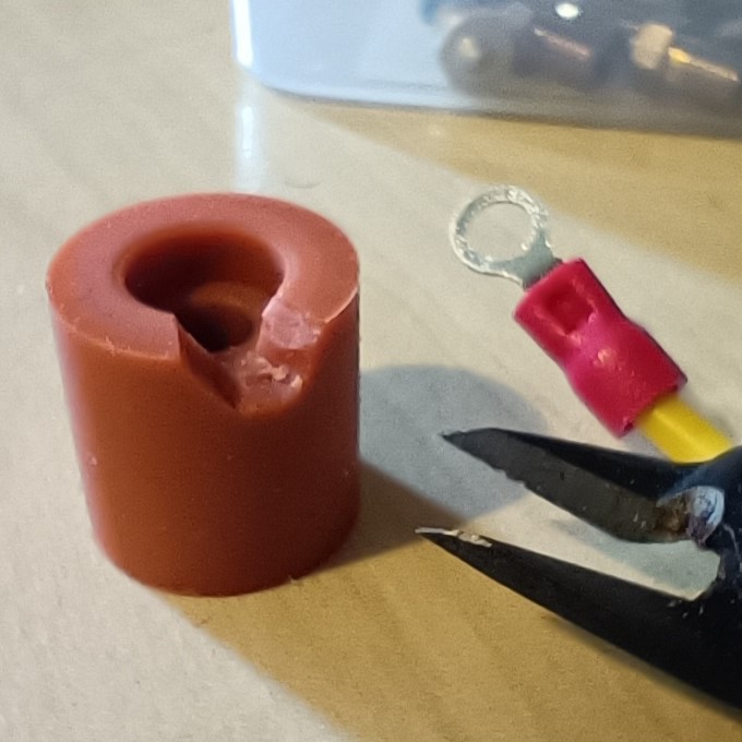
Now that I actually had a crimp termination, I could move onto installing it. I tried a few things and decided that the best solution would be to use some cutters to cut out a small (30 degree or so) portion of the top ring section of a silicone spacer:
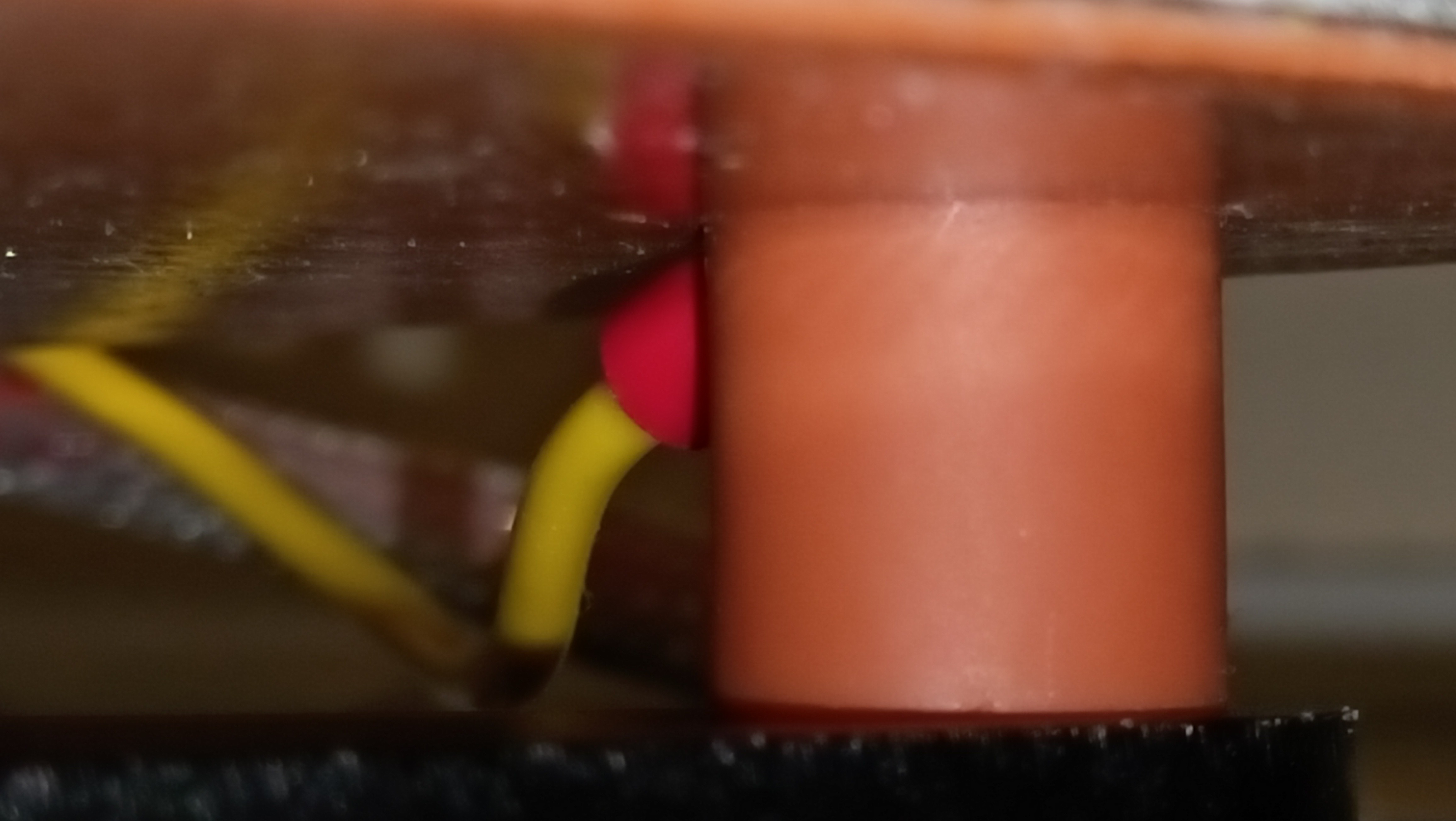
Then I lightly bent the ring termination so that it would screw on the underside of the bed flush, put the ring termination on the bolt and followed it with a thin M4 brass nut, using a 7mm spanner to tighten it. Lastly, I placed the spacer back on and it seems to have all worked as the spacer is in contact with the underside of the bed and my multimeter reads 0.0 Ohms between the bed and the other side of the yellow silicone wire.
Lastly, I've thread the wire through the sheath.
[Moved to it's own project: https://hackaday.io/project/190831-coaxial-hotend/log/218383-tm-design-and-fabrication-optimisation]
[18 March 2023] Ok. I'm trying to print Tetent Concept3 and I've encountered the strange behaviour again:
So it seems that there's actually a zone between 180 and 220 degrees where the readings are not correct.
However, it seems that (other than that one mystery hiccup at 115C), the temperature reading is fine if the hotend cools down to 45C.
Maybe some component is overheating and I should turn the internal fan on? Right now I've got an external fan pointed at the DP2's general direction and I'll see if I can make it though the rest of this 90 minute print.
[perhaps 3 minutes later] Well that didn't last long at all:
It seems that cooling down to 140C works too...
[23:07] Nouhhh my restarts are now proving ineffective!
[23:14] Okay alright pack it up guys. This print is a fail.
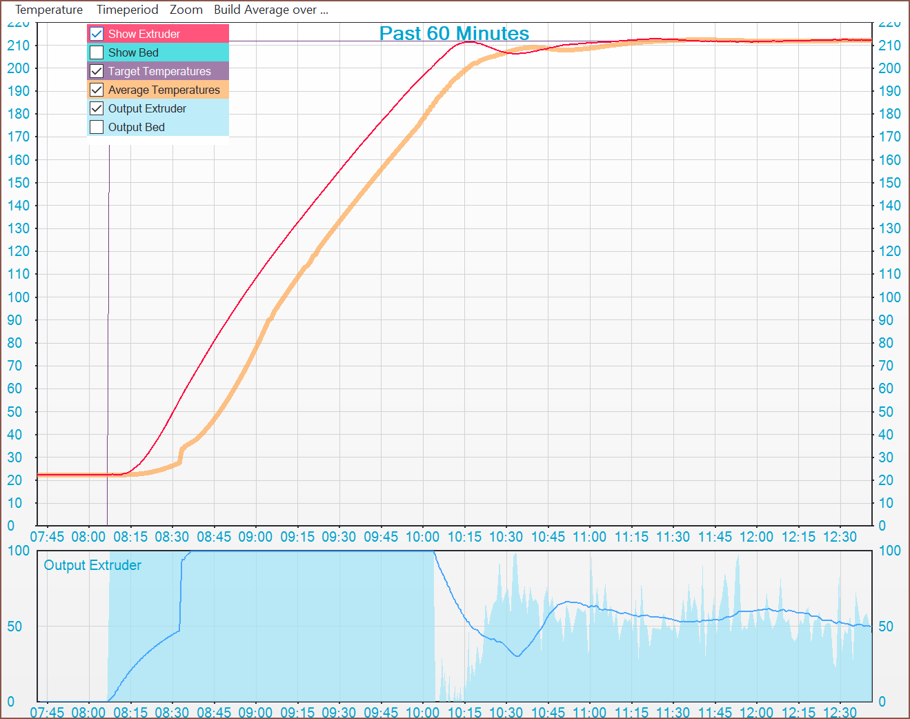
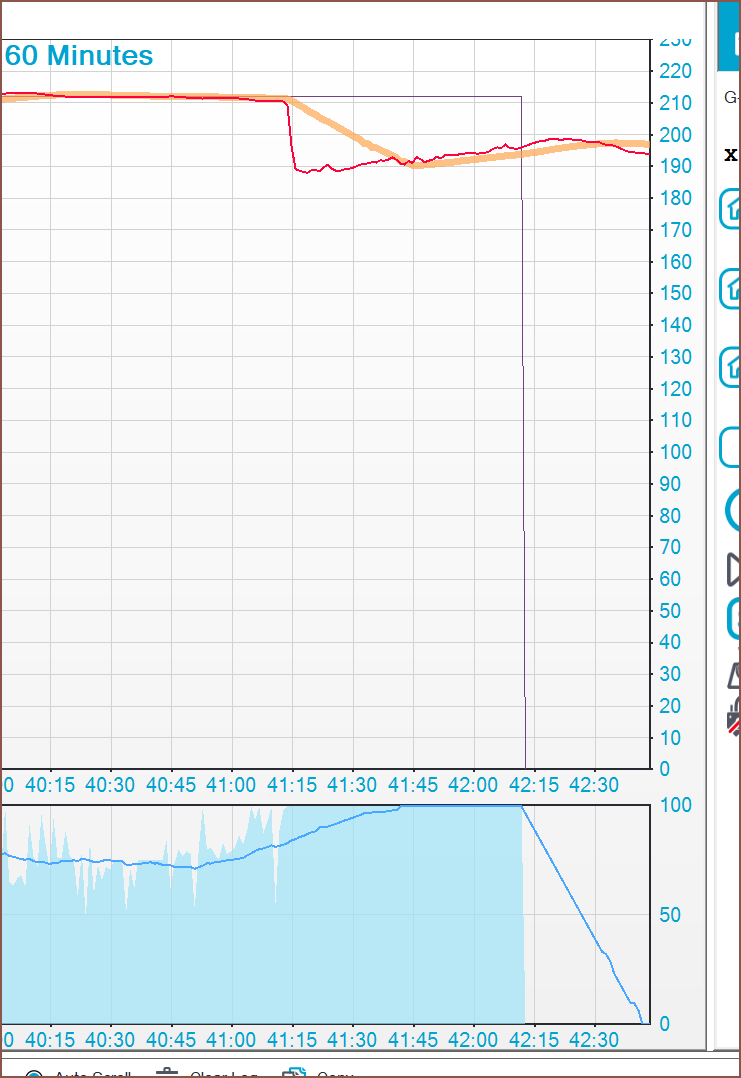
[15:42] As mentioned in a comment here, my DP2 is having a thermal runaway condition where everything is printing just fine and then BAM out of nowhere I tank from 212C to 189C or so. So far, I've taken off the silicone sleeve and, other than the bottom of the nozzle, it's one of the cleanest v6 blocks I've ever seen on a printer (that hasn't recently gotten a new one). The thermistor is the cartridge style and very solidly in there, so it doesn't seem to be the cause of a loose one.
[15:56] Went into the wiring and all terminal blocks are tight. Hm... could it be software? I'll track the temperature though Repetier to get more insights.
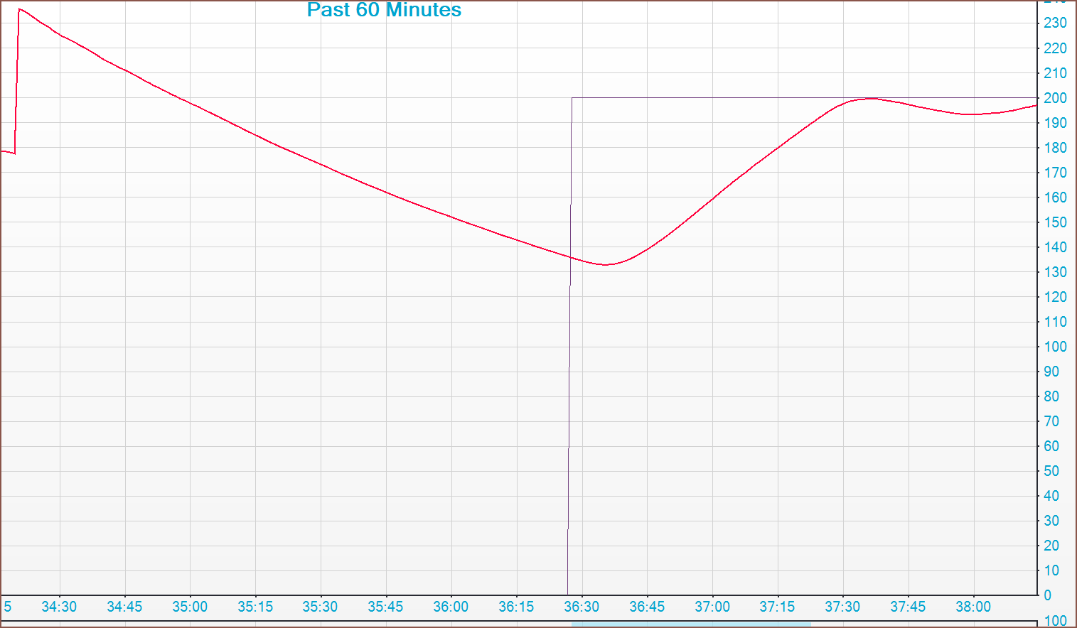
[16:13] And were live:
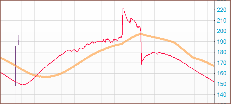
[16:44] Ok... all looking goo-- WOAH WOAH WOAH THERE IT IS!
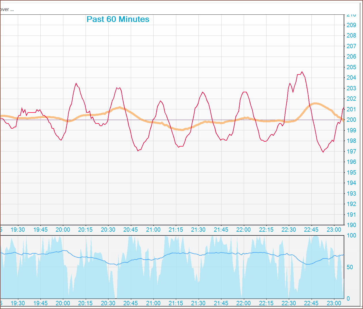
then again, it might just be a difference in scales. The gradients look about the same now.
Maybe I should try printing at 200C and see if that eliviates the strain on the heater cartridge? Also, that little dip is when I restarted the printer, just incase something was restart related.
[17:15] I'm currently compiling the latest Marlin 2.1 bugfix to see if that changes anything (if this current 200C test fails)
[18:02]
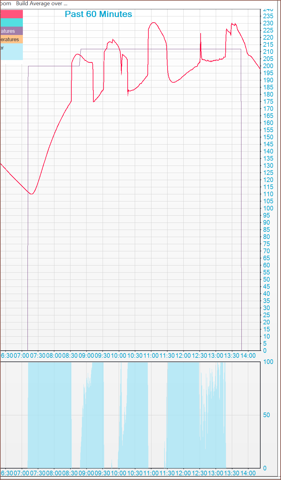
Earlier into the print, I was getting large temperature swings:
[19:13] Okay the print finished (and just in time because the part fell off as soon as I lifted the magnetic build plate). I'll try an autotune with the fan at 100% to see if that can resolve anything, and then flash the updated firmware.
[18:28] 6 hours ago, I was looking at the Tetent Timespy [gd0136] concept I had modelled the day before and desired to print it. I thought about the printers I had available. The CR600S is completely out of commision and the Tevo Flash needs a fan shroud tweak and a new fan, but I couldn't think of anything hardware related that stopped me from using the Linear Plus.
Powered it on and it homed fine, so I started an Auto Bed Calibration and that's when I found out that the issue was firmware related. The printer wasn't moving to the correct next probe position. So, 5 hours ago, I got started.
So my Marlin Github is set up to have "common" as the main branch that has all the common changes I make to all Marlin printers, and then printer specific branches. Since I didn't want any suprises, I pulled changes from common as-is instead of first pulling from marlin/bugfix-2.0.x. About an hour later after accepting changes, I was ready for the first compile.
Yeah that make sense.
So there's a bunch of new things I have to accept in the config files, and so I finish one and then see this:
Thus, I "Accept all incomming" for maybe 20 files at a time, since, for some reason, I couldn't do all at once successfully.
Yeah... this is probably one of those "caught inside a merge" kind of errors. I don't know what they're actually called, but I imagine that a non-compiling codebase was pushed to the branch. I copy out the 4 files I've modified, hard reset the repository, paste the 4 files back in and... same result.
So after like an hour figuring out how to pull from 2.1.x and not 2.0.x, I go through the config and find out what a TPARA is:
I accept changes in the config files, then do the same copy-out strategy mentioned above.
FINALLY WE HAVE GREEN
The changes from the initial LP firmware is
First time trying the auto calibration and the Z was moving down at a snail pace.
Then the probing looked pretty gittery so I was thinking it was to do with a low DELAY_BEFORE_PROBING of 70ms. It barely succedded with a standard deviation of 0.49 after 3 iterations. Increased it to 200 and then 500ms and the calibration failed and made it more obvious that the bug I mentioned earlier was still around. For some reason, the printer won't move to the correct location if this value is too low.
I changed DELAY_BEFORE_PROBING to 100ms and increased Z_CLEARANCE_BETWEEN_PROBES back to 18mm/s. I got a successful calibration and after 4 iterations, the screen spat out a s.d. of 0.35. Now it's been entire years since I've last done a delta calibration, but I feel like the typical standard dev is 0.020, but maybe I'm misremembering 0.200.
My hypothesis was that 18mm was high enough for a full auto calibration, but not high enough for the linear plus to move to the...
Read more »I'm going to start putting all my printer repair logs into this project, so it has been renamed.
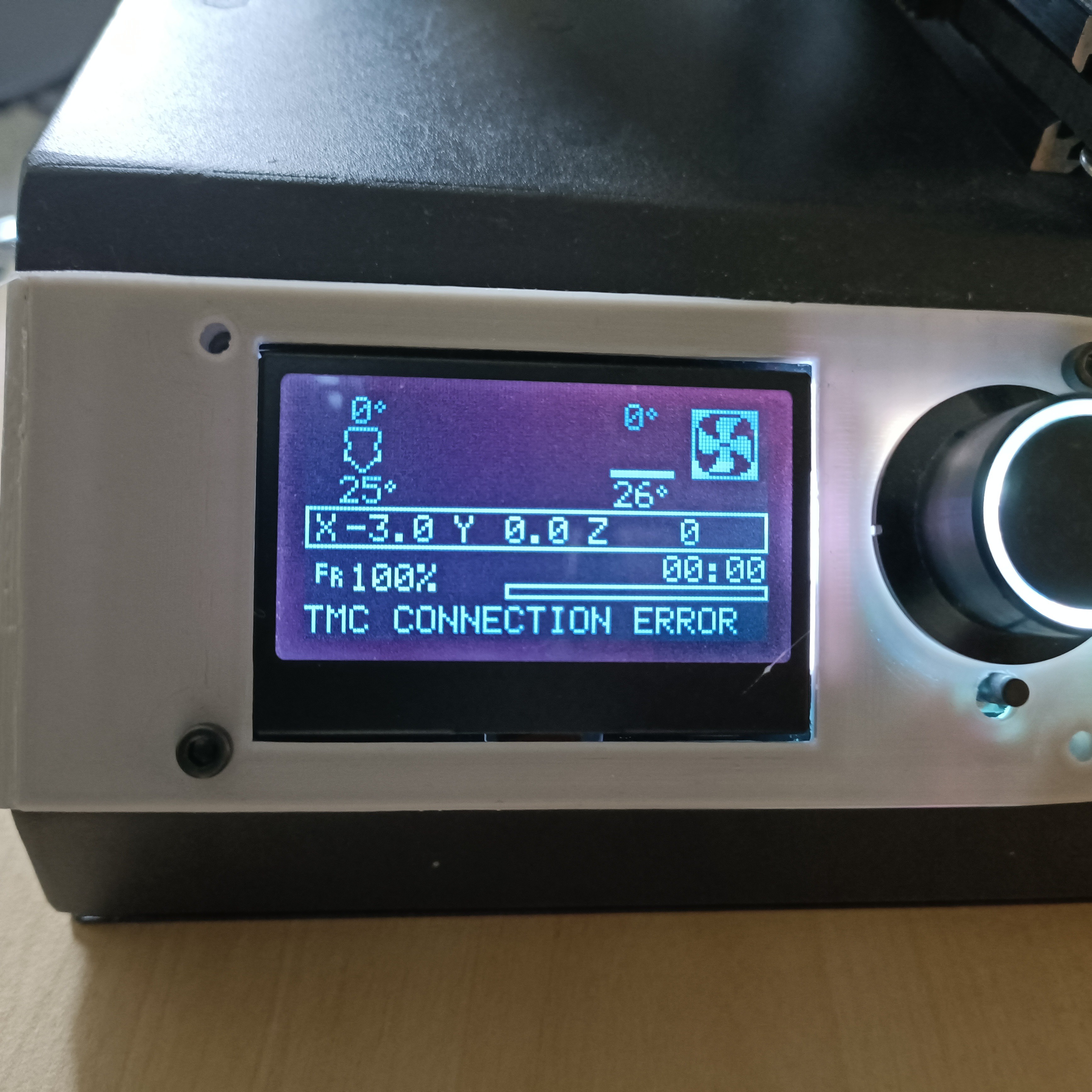
For gd0036, I wanted to see if I can use these drivers (on the S6609 stepstick) instead of (drastically) more expensive (and out of stock) TMC5160s at 36V.
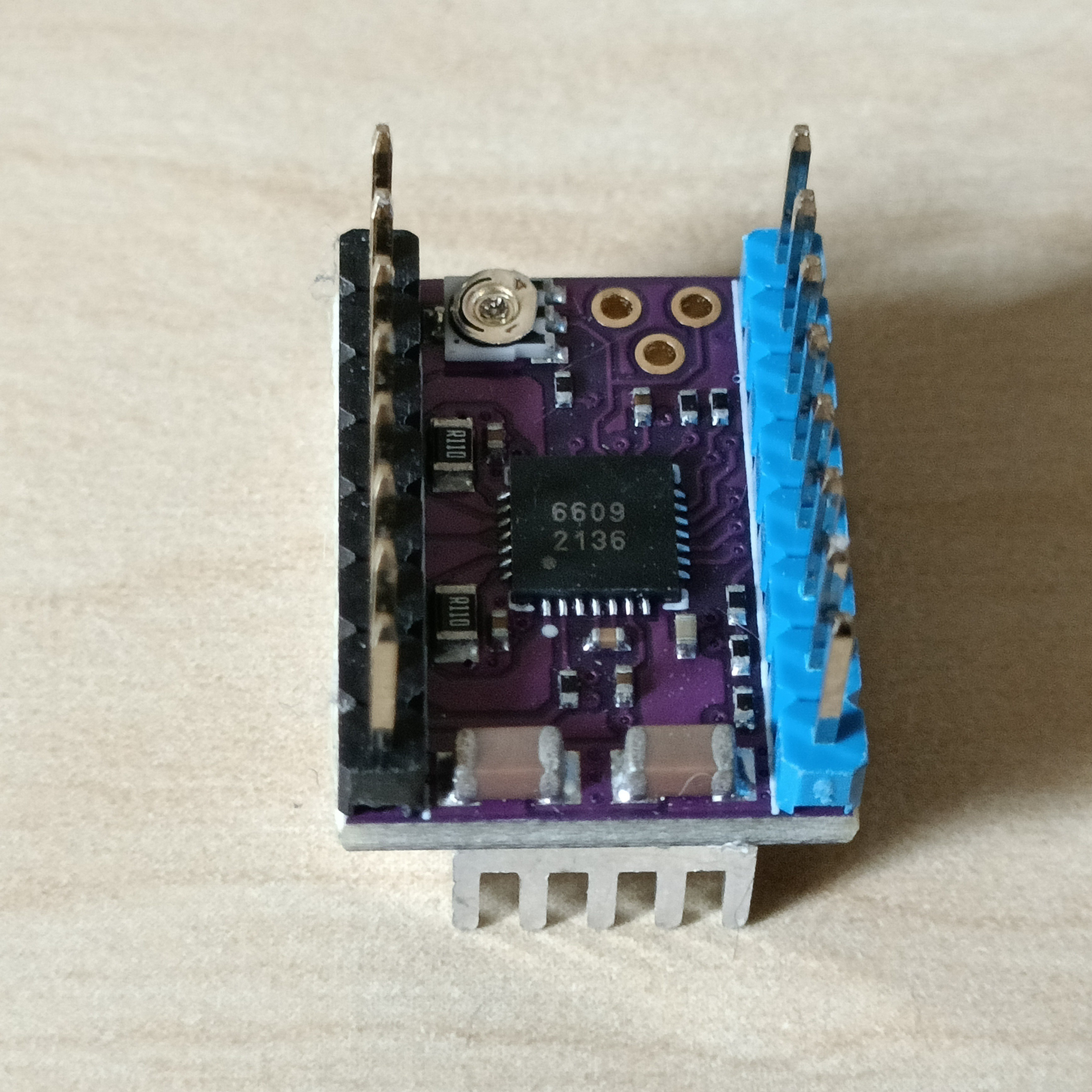
[14:43] I've just discovered that the logo on the board is FysetC's. I knew I recognised that logo somewhere. I've also discovered the datasheet, but I don't have an account so I can't see the other 8 pages.
[15:03] Tried getting some component values, seeing if I could find some kind of rsense.
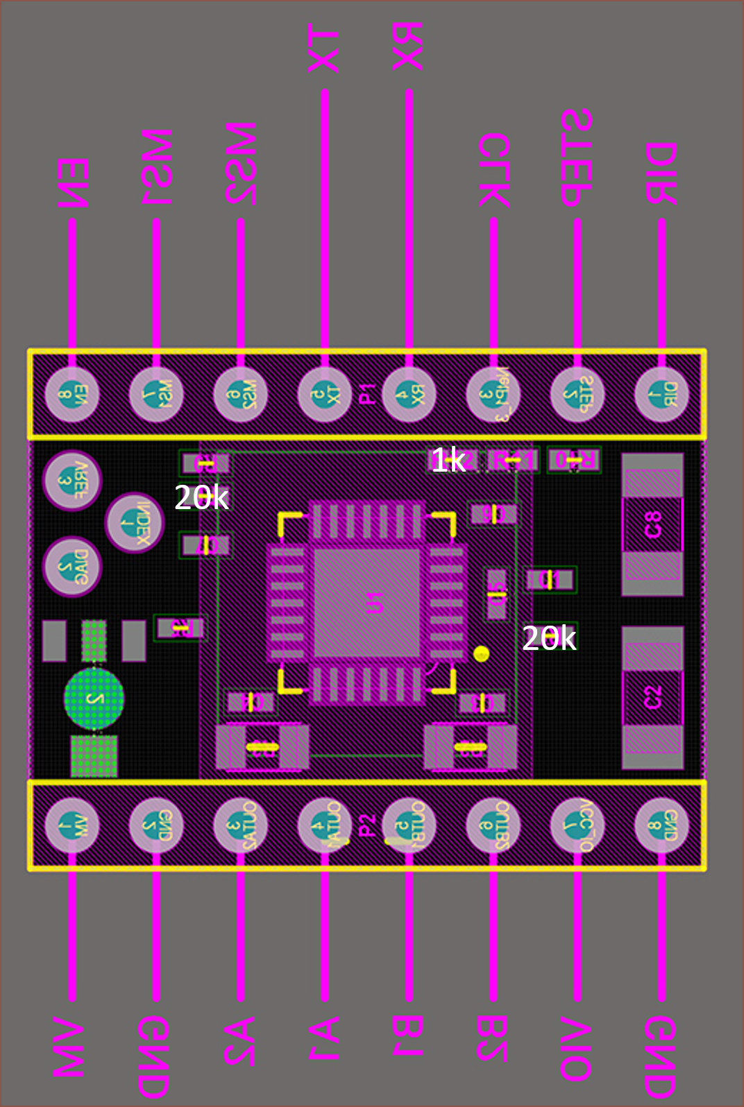 It's not much but it's honest work. Most resistors read as 0ohms. The 1K resistor is for TX and RX.
[16:43] Huuuuh. I was scrolling through this fysetc page on the TMC2209 and I found a schematic that looks awfully similar.
I'm going to continue my testing with the driver set to 2209 in Marlin and see if this gives me any leads.
Wednesday 23 March
[05:54] Fysetc calling their latest TMC2209 driver the S2209, as well as similar text layout, adds more evidence that the S6609 is a 2209 clone from FysetC. Judging by the schematics, it also looks like Index and Vref were intended to be swapped on the S6609 v1.0 PCB to match the S2209 v3.1, but there was an error when setting the header pin numbers.
Also, without UART, both chips can only be set to a maximum of 1.77A R.M.S..
[06:46] I just realised something:
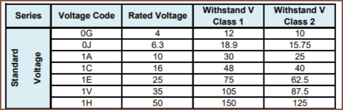
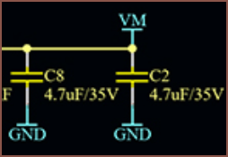 That's the 2 relatively large Voltage(motor) capacitors. This seems like a situation where the chip can do one voltage (which is the one advertised), but the stepstick can only work to at a different, lower voltage. Nothing short of penny pinching here. Micropennies actually. Further research uncovers that the general consensus is to use capacitors up to 70% of rated voltage, which means I'd need at least 51.43V capacitors and these current capacitors are really only for 24.5V usage. This knowledge is interesting though, as the SKR Octopus Pro uses 63V capacitors, which should equate to a 44.1V recommended max input voltage.
[08:29] Looks like the S2226 has an even more identical pinout, suggesting that the "judging by the schematic" stuff I said at 05:54 is irrelevant.
[18:04] I've just discovered that MLCC capacitors (the brown ones on the stepstick) don't require derating as they have "higher voltage strength".
Phew. I was worried all day about having to desolder and resolder like 32+ stepsticks; an entire reflow station is still probably cheaper than a couple of HV 5160 stepsticks (that have just shown up on virtual shelves). Speaking of those stepsticks, it seems that the DIAG pin is the only one needed for sensorless homing.
Thursday 24th March
[10:05] UART woes aside, I thought I'd see what these drivers even sound like. Can confirm they are TMC2208 grade. I feel the 6609 is like 1dB quieter on the Y axis when I did the test, but the 2208 seems to take the win when playing...
Read more »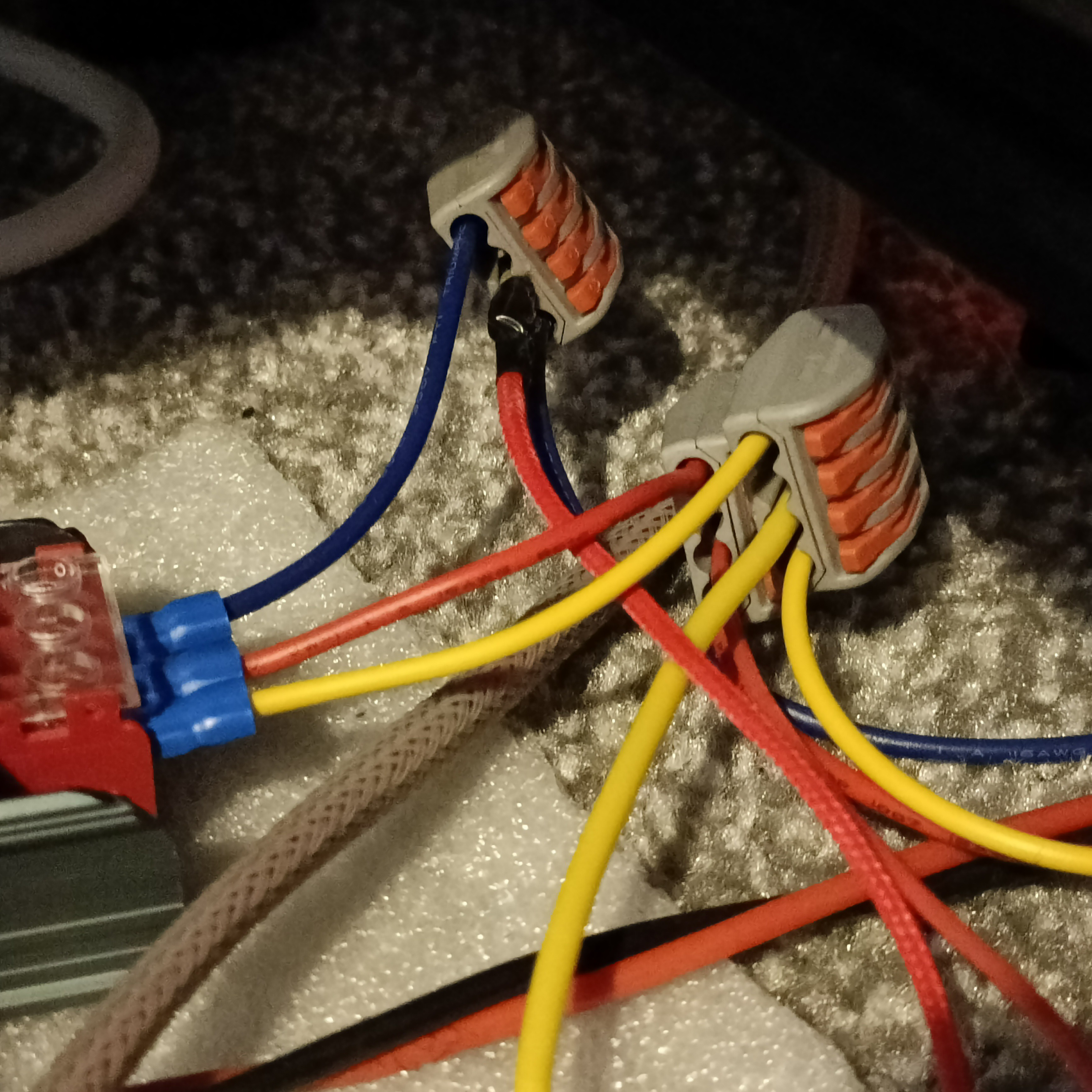

 Maybe the fan wasn't pointed precisely enough. I didn't want the part to warp or anything. I'm trying again with an even more directly pointed fan.
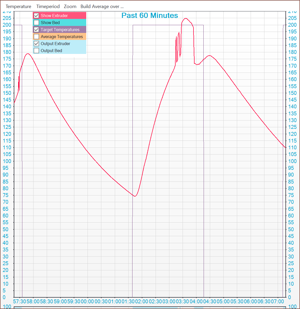
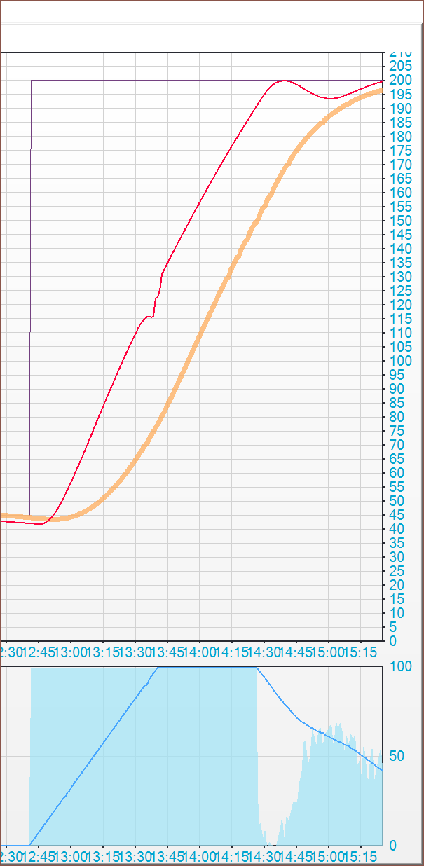
 Yeah there's ABSOLUTELY no way I'm loosing 20C in like 2 seconds. And then, max power was injected in yet the temp is climbing much slower than it should be (so I turned it off). Something else to note is how high the power% is. Seems like 70% to keep at 212C for some reason, especially since it was hovering at 50% at the start of the print. This could be caused by the hotend being further away.
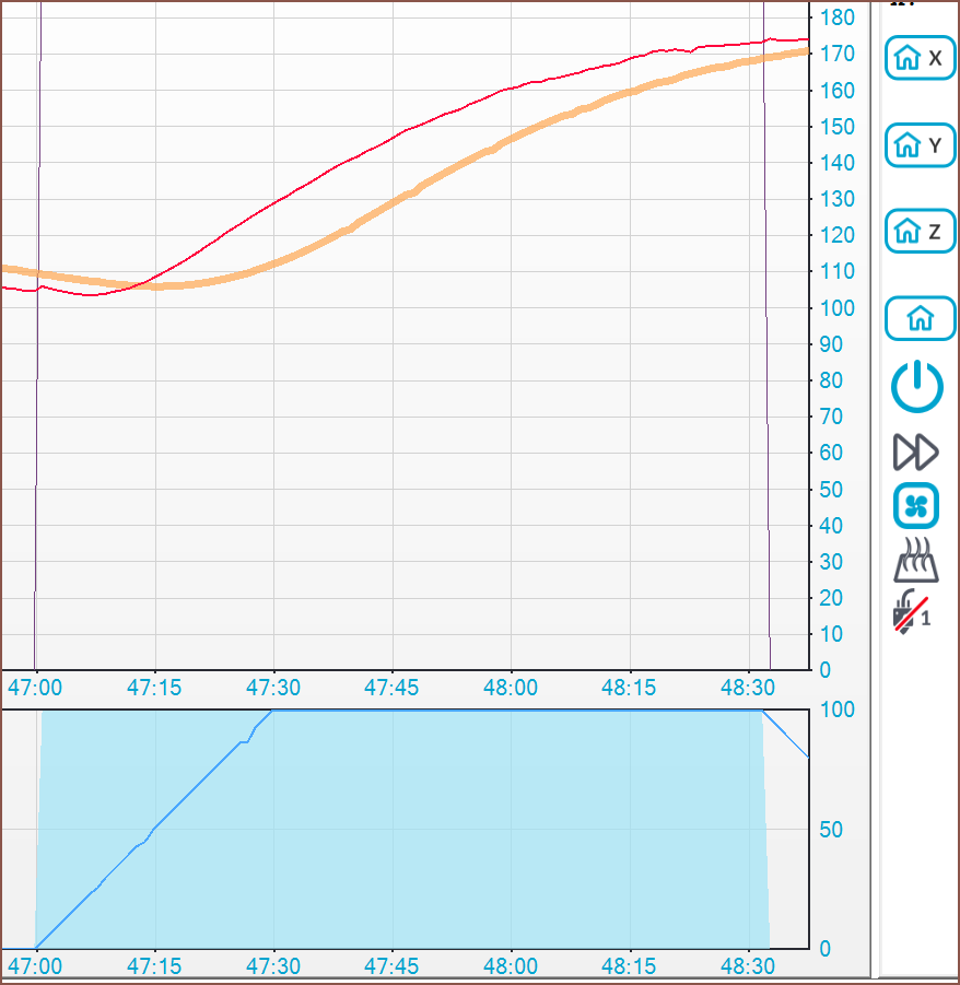 I cooled it to 100C and then turned the heater on again... and it's looking to plateau at 180C. As you could see from the first graph, that certainly shouldn't be happening.
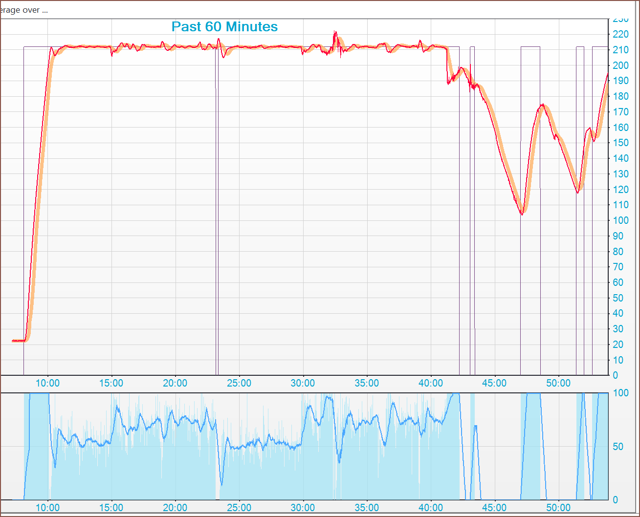
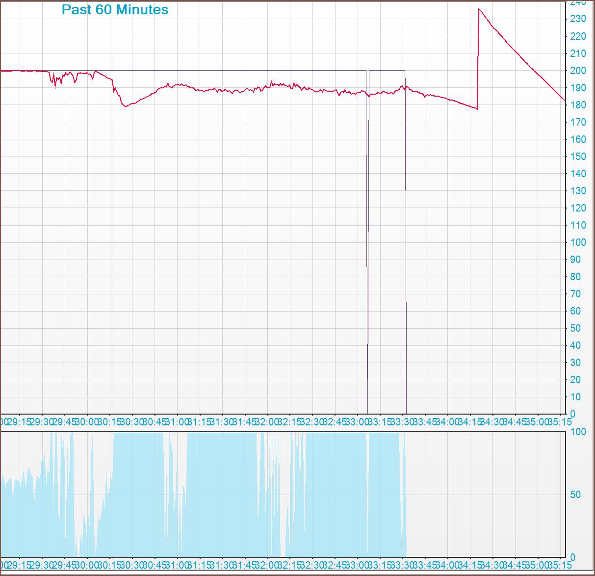
 They've seemingly died down, and then I got this suspicious spike:
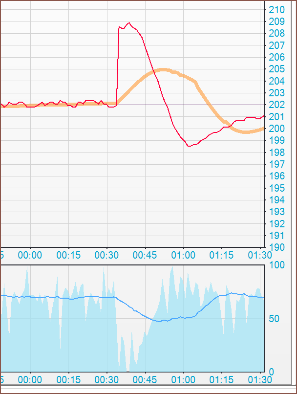 I wonder what this could be caused by. Maybe the passively cooled internals are messing with the ADC? I have also opened a window so the ambient air is a little colder.
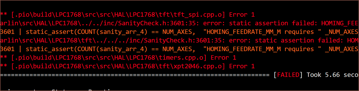
 Yeah I thought I could get away with this and marlin would automatically apply the value to the other 2 axes.
 Oh yeah... that's right. There was some sanitycheck bug I found when compiling for the DP2. Instead of going into that file, adding a "!" and recompiling, let's take our chances and spin a win on a git pull bugfix2.0.x -> common.
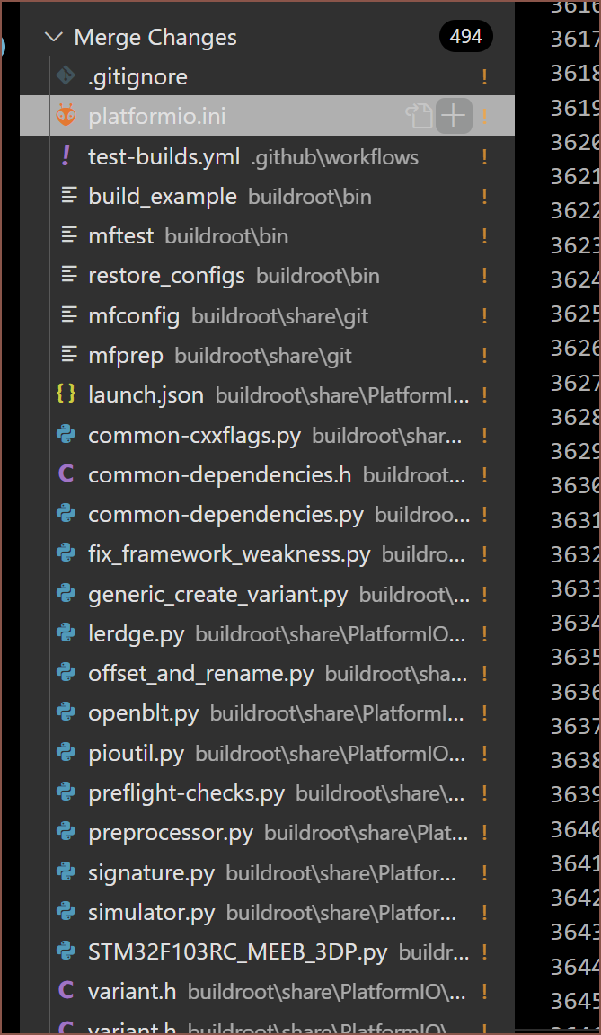 Why is there so many things that failed to merge??? I haven't touched any of these files!
 Wait. There's a 2.1.x!?
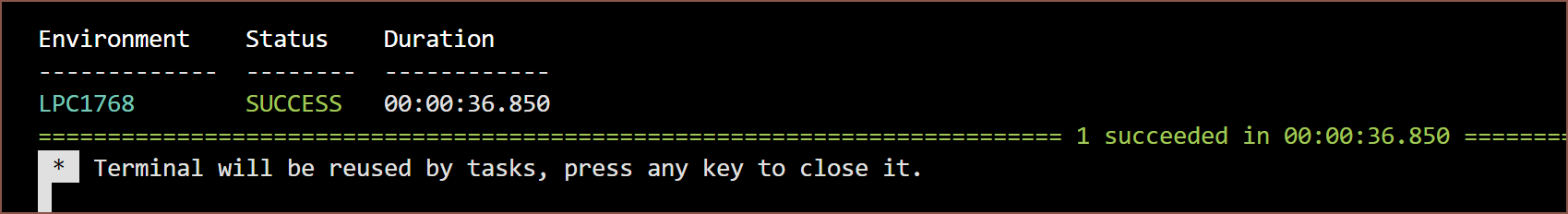
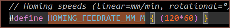
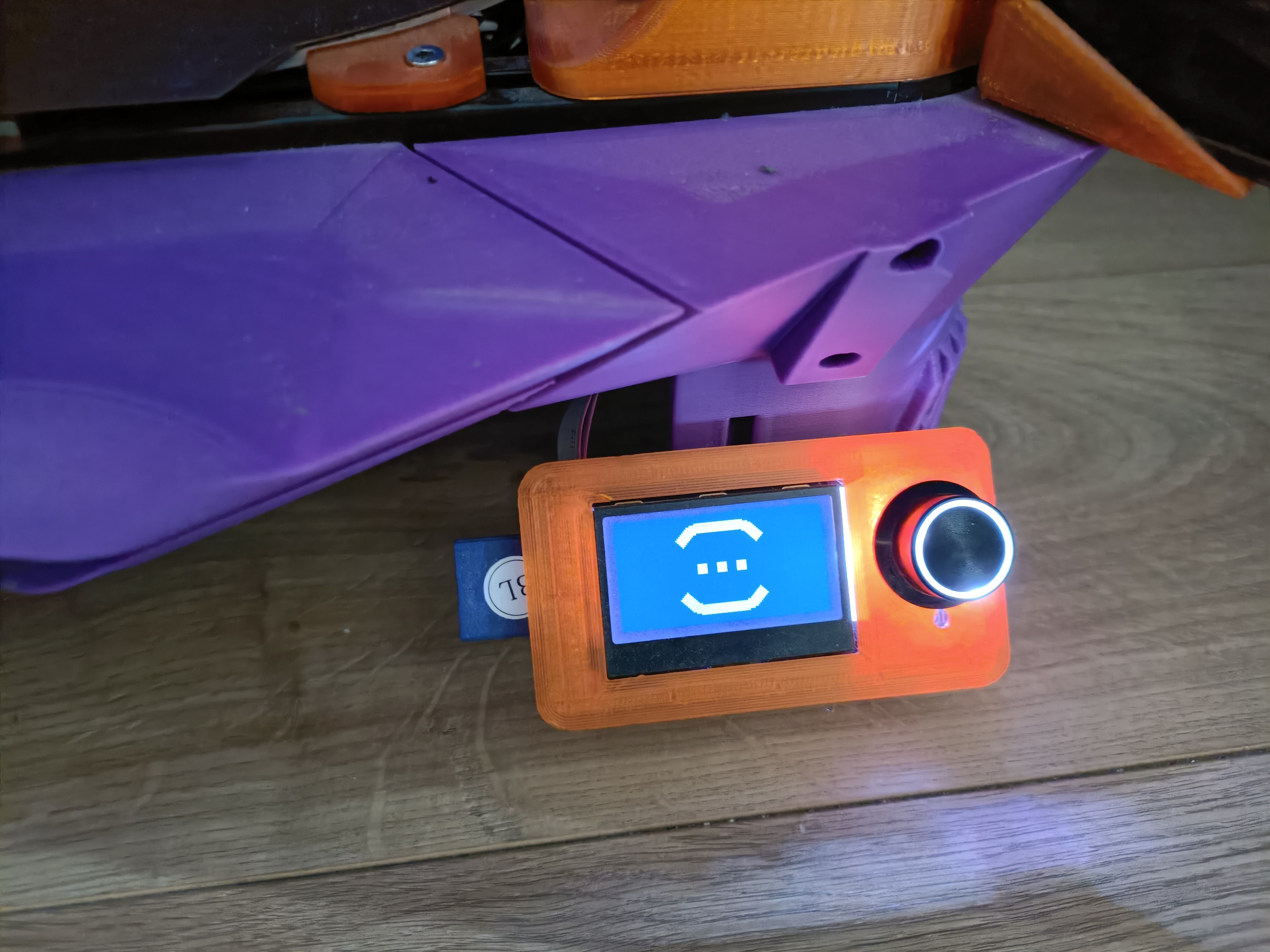 Man it's so nice to see that logo, signalling a successful firmware flash.
 This is probably why. Changed that to 120mm/s.
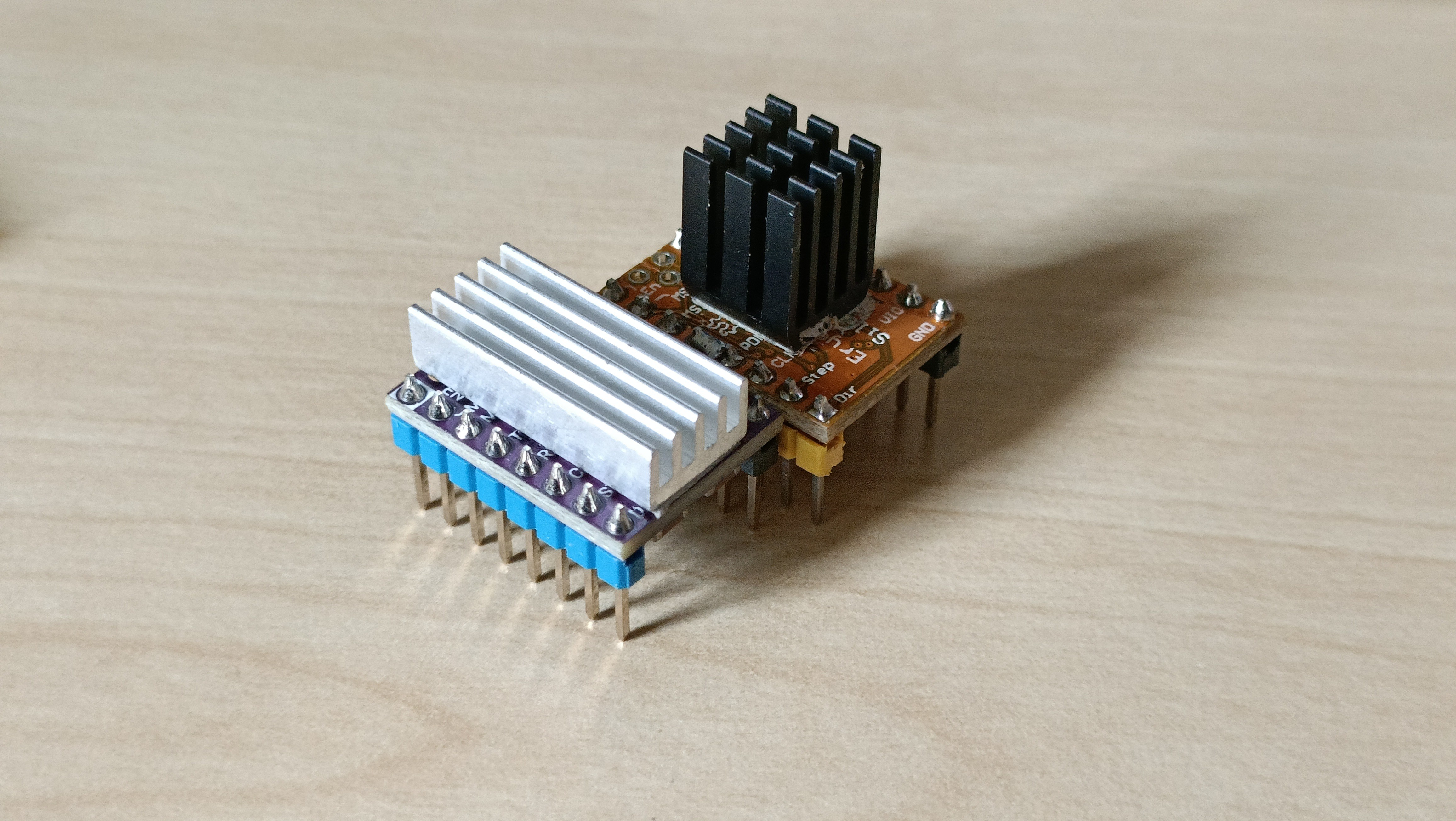
 so it's not as simple as
 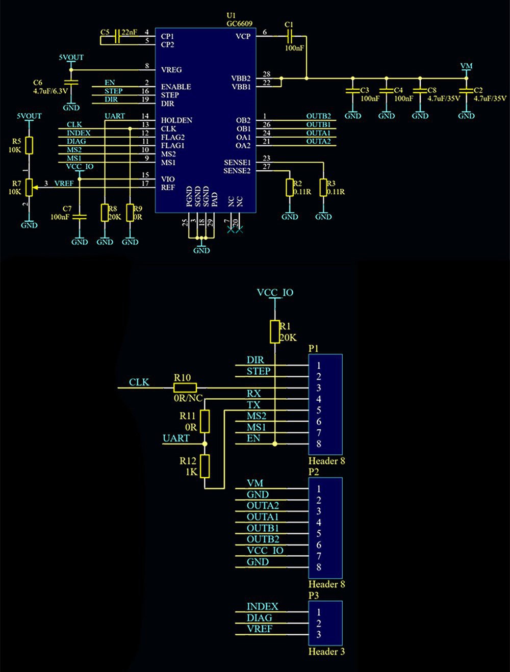 Turns out 0 ohm resistors actually exist. Seems that the 2 large resistors are the sense resistors, coming in at only 0.11 ohms, so it makes sense why I couldn't read those.
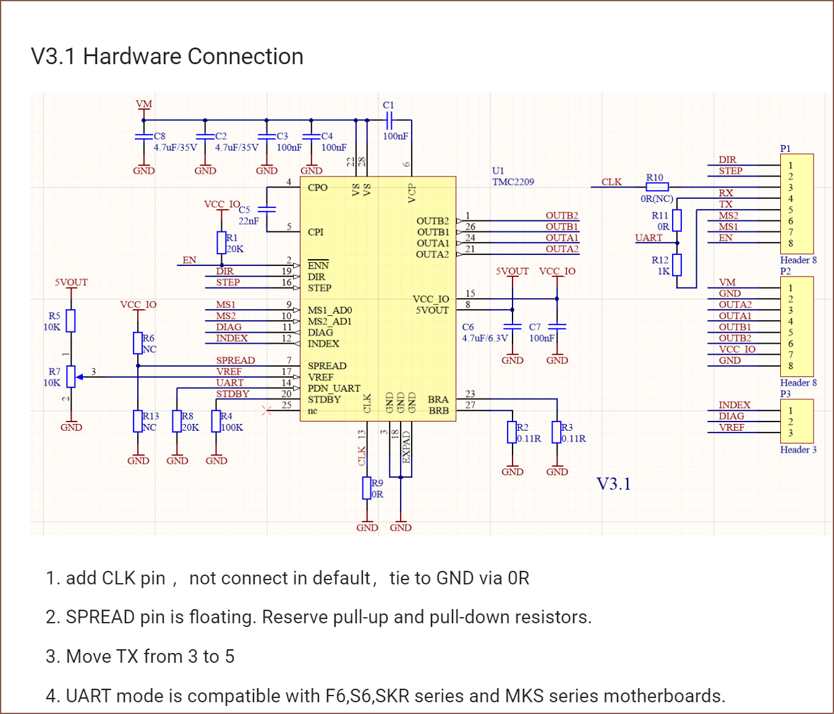
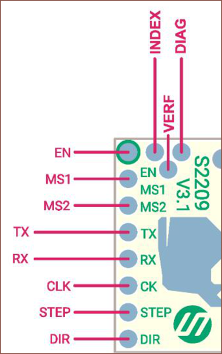 It's likely possible to correct the mistake with an extra long 2 pin header which is only soldered to the DIAG pin (from bottom side) and shrinkwrap over the vref pin, and then some wire or solder bridge from Index. This also menas that a shorter heatsink will be needed if the stepsticks are mounted like in the SKR instead of like the SKR Octopus.
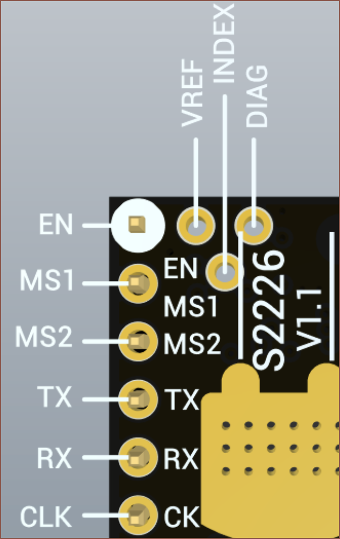
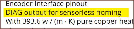 Thus perhaps the elaborate solder job I mentioned earlier wouldn't be needed at all. I'm not planning on using sensorless homing currently, but it's useful information for the future.
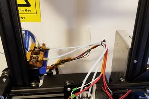
 P
P
 bfoz
bfoz