Just some more details about how the Enigma is designed.
You can find the FreeCAD files and STEP files on GrabCAD.
While researching the Enigma it became quite apparent that the machine went through multiple design revisions. Not just the obvious 3 to 4 rotor versions, but also various changes that were mostly likely caused by material shortages during the war. Also there were changes made to make use easier. As a result of the variations available I decided to try to keep the look and feel of the Enigma while using inexpensive parts and simple manufacturing methods, i.e. 3D printing and limited CNC routing/milling.
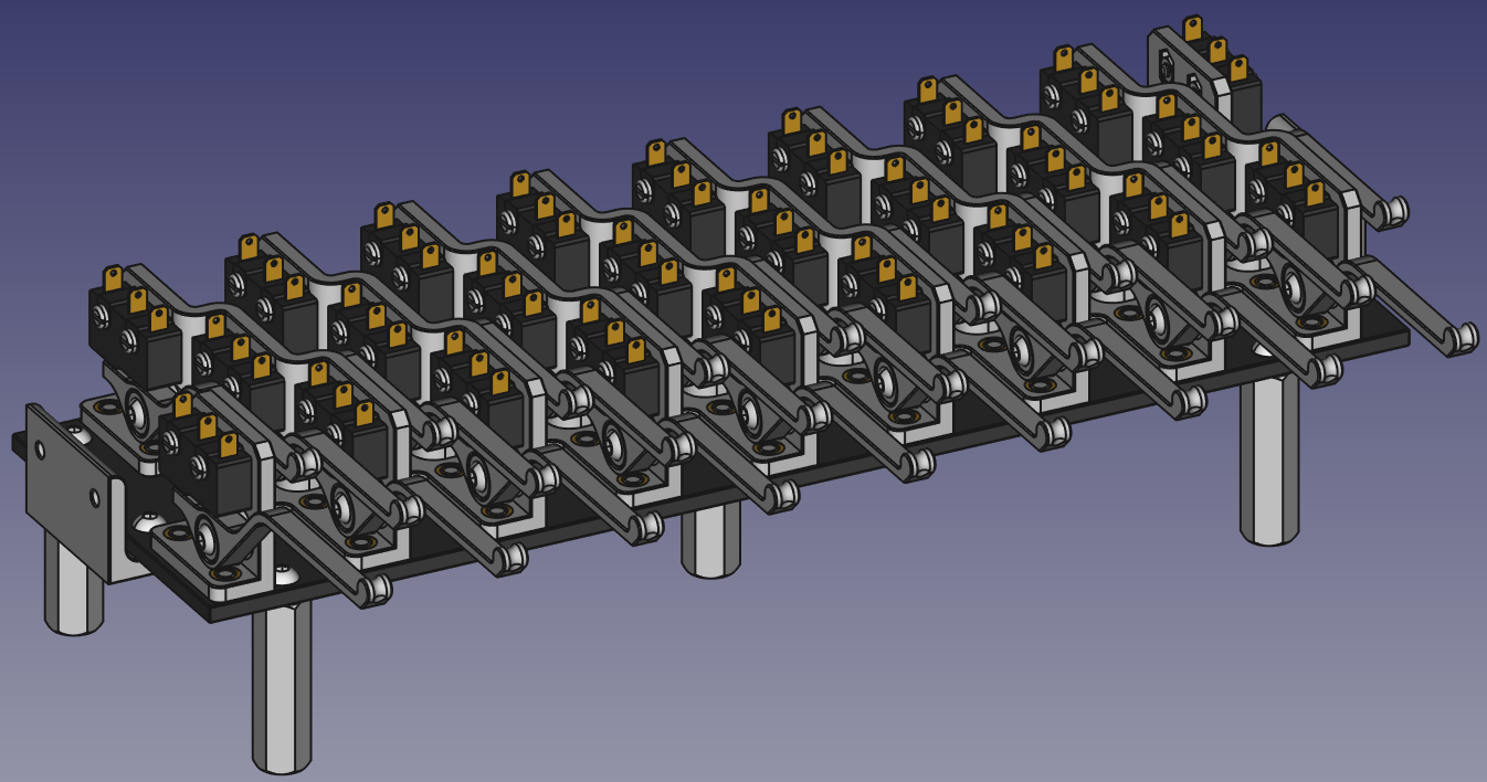
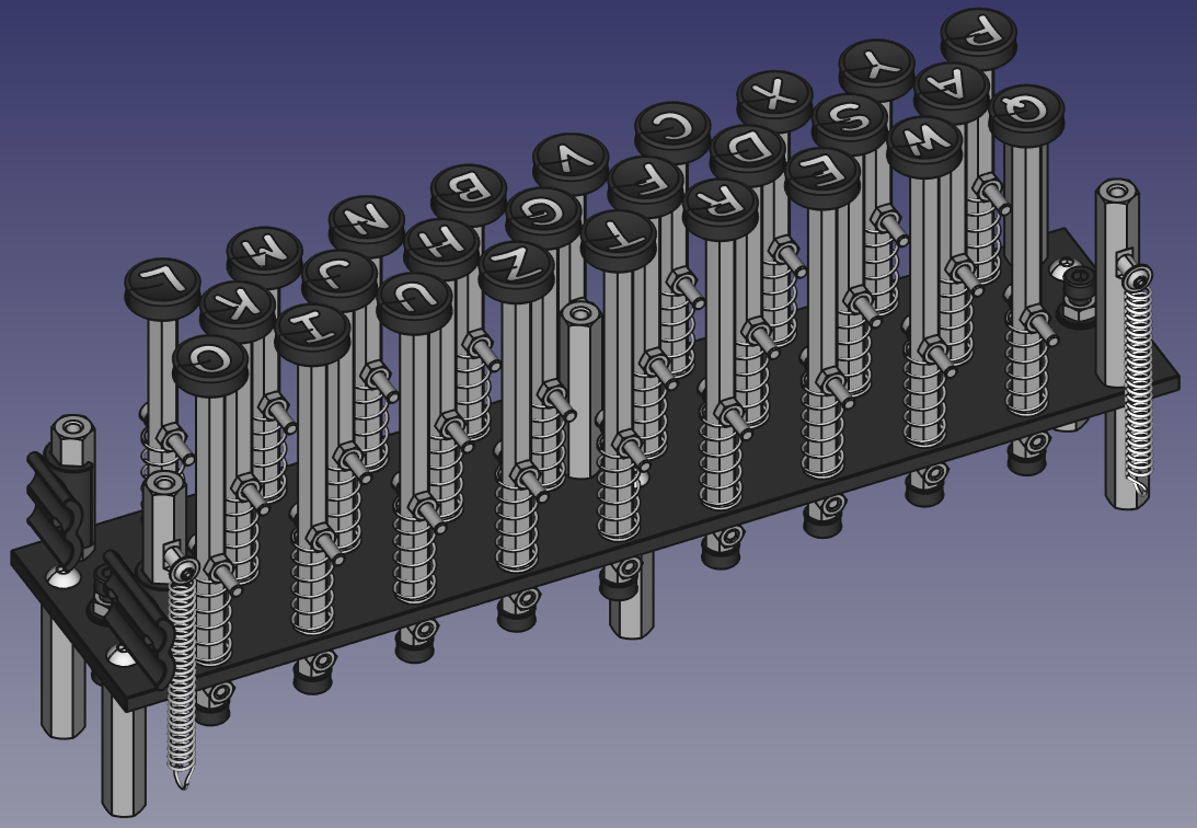
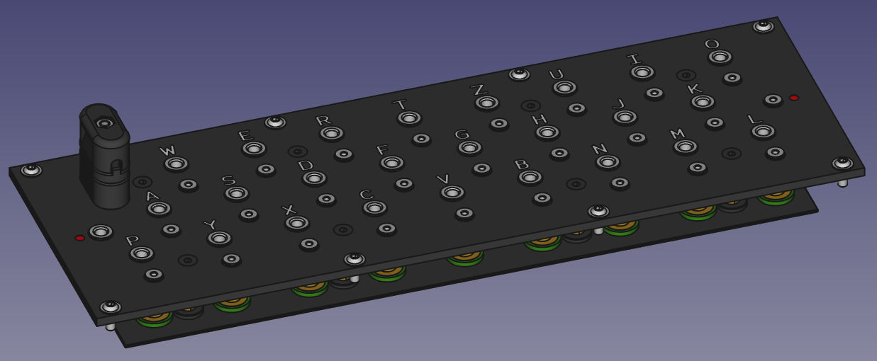
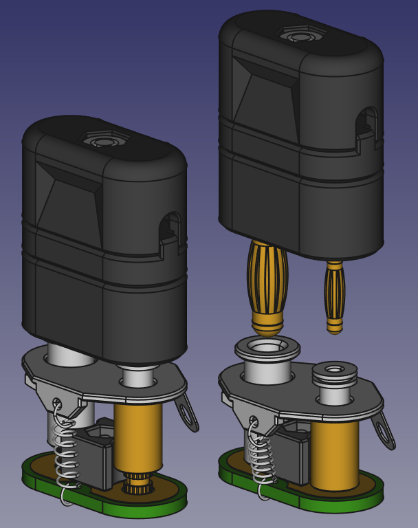
For the switches I decided to use inexpensive micro switches with custom lever arms. This arrangement allowed me to use consistent keyboard key shafts. You might also notice that I decided to use black resin 3D printed key tops and fill the letter cut outs with white Miliput epoxy putty. They will look very similar to the key tops found on a lot of the Submarine Enigmas, and be a lot easy to manufacture than the brass key tops with letter inserts and glass lenses.
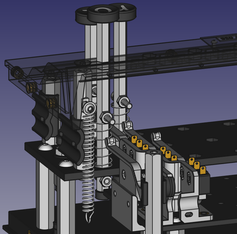
 The original Enigma machines used spring board style switches and different key shaft spring arrangement for each row of keys.
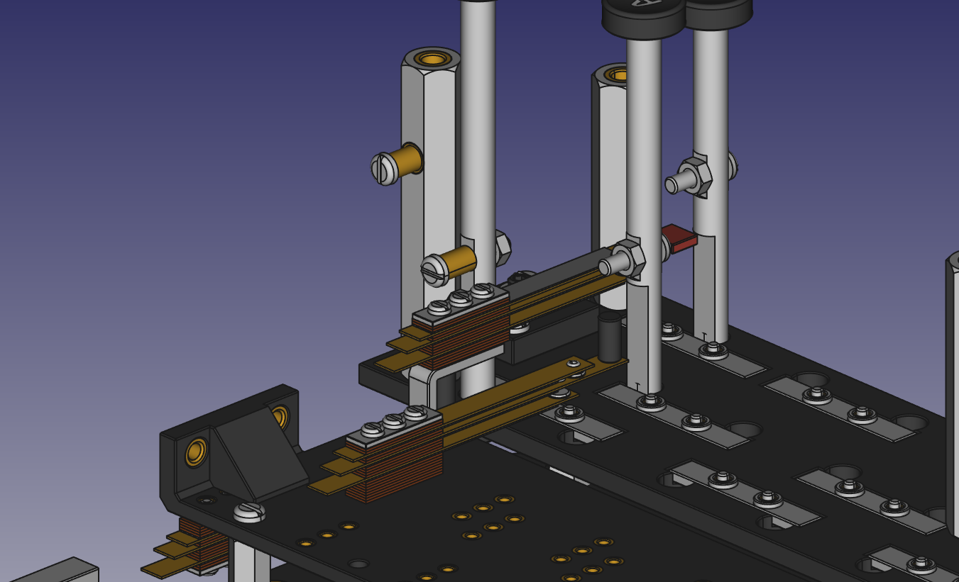
Also I decided to use hex stock for the key shafts to eliminate a lot of parts used for anti rotation. The hex shafts will also allow for easy drilling cross holes for travel stops and spring/switch triggers. Using 3D printing it makes it easy to create the hex holes in both the switch stop plate and the switch cover plate.
For the Lamp panel I designed a circuit board to use E10 sockets to accept the bulbs and make all the common connections much simpler.
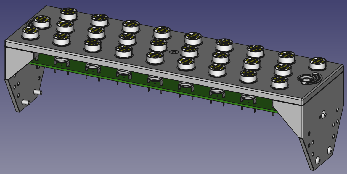
Also I plan on using E10 LED bulbs as they should be able to be more than bright enough, run cooler, have a longer life and still be short enough to easily replace the original flat top (squished) incandescent bulbs.
The next major simplification is the patch panel, and the banana jacks and plugs. After exhaustive searching I have found hardware for 2mm and 4mm banana jacks and sockets that can be made to work.
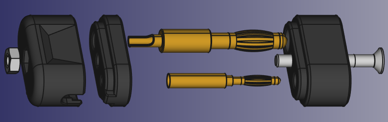
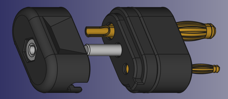
The shorting bar for the patch panel will be a pcboard with a guide block and nylon screws that feed down the barrel of the banana jacks. I will be tapping a piece of brass tubing that will act as the guide and nut for the 2mm banana jack.
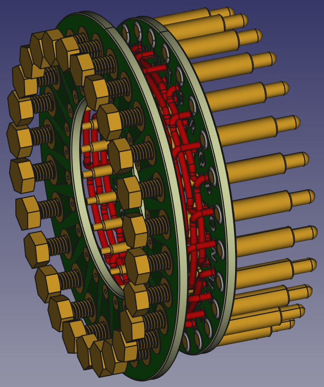
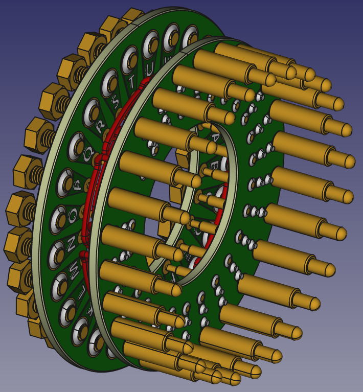
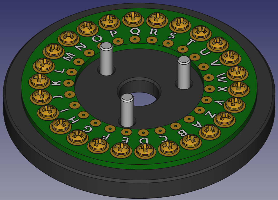
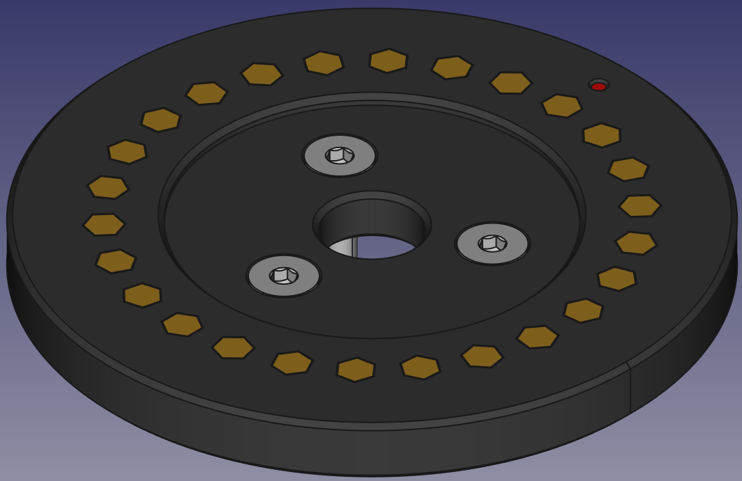
The next major piece has to be the Rotors. The first generation rotors were beautiful and complex, so....
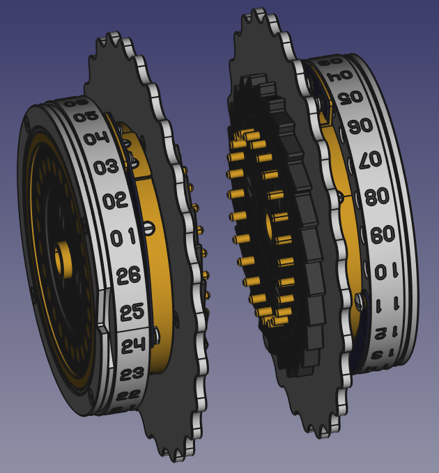
I designed the rotor to mimic the rotors used towards the end of the war, very similar to the ones seen in the recovered Submarine 4 rotor Enigmas. As the rotors were all backwards compatible I feel very comfortable they will look good.
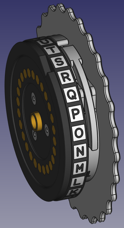
My design "just happens" to be much simpler with fewer parts than the early versions of the rotors.
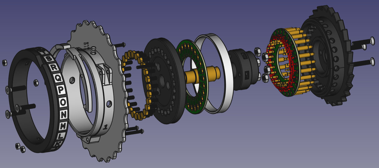
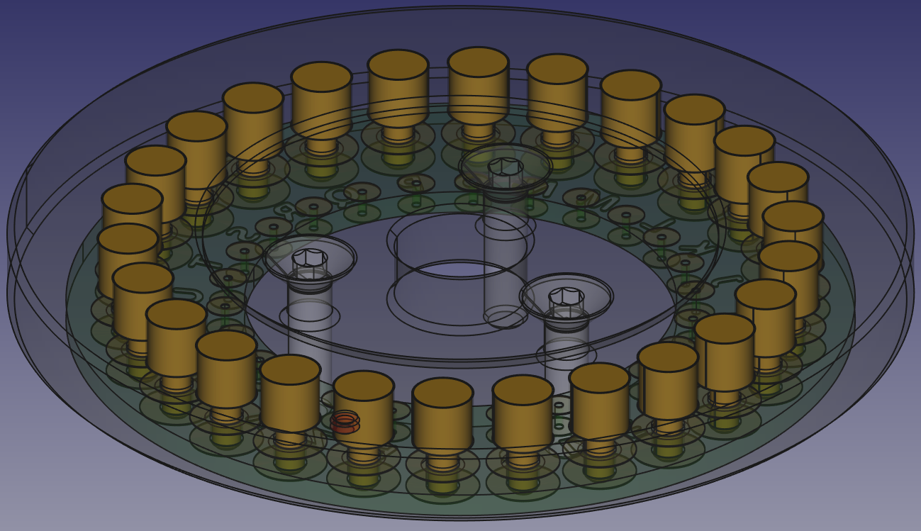
Using 2 pcboards in the design makes it very simple to do the wiring. The input contacts are high current Pogo pins that are very similar in size to the originals. The input pins are soldered to the input pcboard and cross connected with individual wires that can be wired as the various rotors were wired. The input pcboard connects to the output pcboard with smaller Pogo pins. The output contacts are 2.5mm brass standoffs that soldered to the output pcboard and sanded flush to the output contact plate.
t
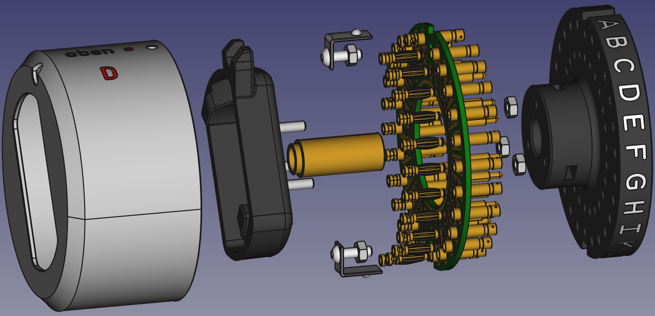
For the reflector I have elected to use the programmable "D" style, as it could be used on the 4 rotor Submarine Enigmas in place of the 4th rotor and the thin reflector. The "D" reflector even has the D on the case to be visible in the 4th rotor's window. Using the "D" reflector in a three rotor Enigma essentially make's it the equivalent of the 4 rotor variation.
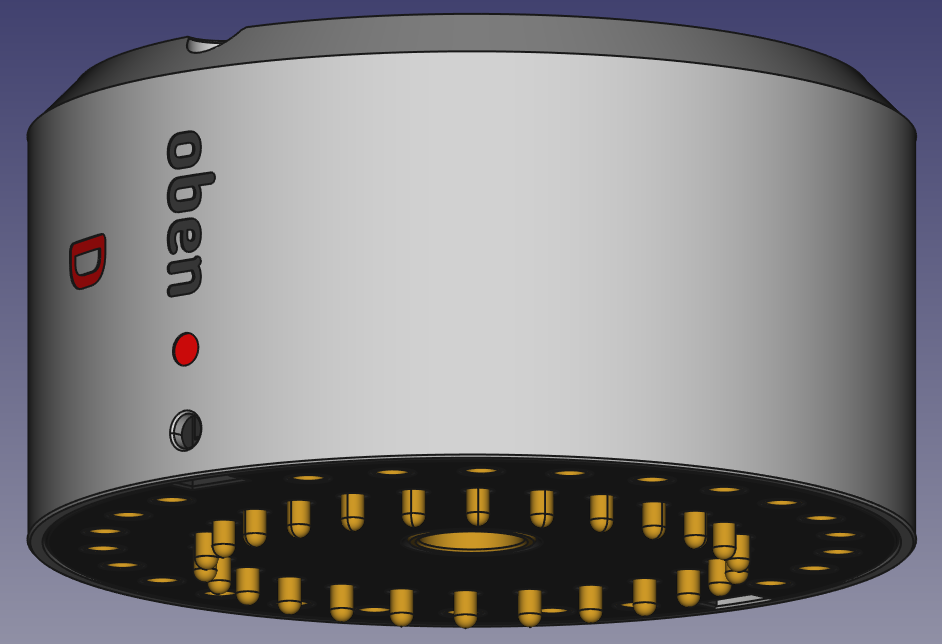
I designed the reflector to use a pcboard to connect the high current Pogo pins to the 3mm banana jacks, eliminating a bunch of parts from the original design.
The base, rotor supports and detent assembly were redesigned to make 3D printing easier and stronger while still...
Read more »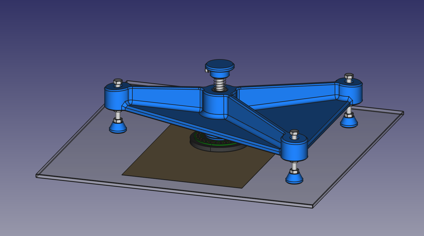
 zapwizard
 Maximiliano Palay
 Chris Mitchell
Hello,
You have done a amazing job. Thanks for putting the design up for others. Not to take away from it, just so you are aware. Here are some others doing something similar. If you wanted to compare.
The main one being R.D.E Enigma https://wiest.home.hdm-stuttgart.de/enigma/ from hDM university in Germany. They have STL files available and manual for printing and putting it together. I'm currently in the process of printing their design. It's still in beta but probably will be made available for all soon.
Another one is here. https://grabcad.com/library/enigma-i-replica-1
Dylan