 Nate Rivard
Overview
The next subsystem we're going to examine is the clock select logic. SPI orchestrators and peripherals all share the same clock, generated by the orchestrator, to stay in-sync. Peripherals may only accept specific ranges of frequencies so the orchestrator needs the ability to generate a wide range of frequencies for better compatibility.
Remember that in our control register we dedicated 2 bits (so 4 possible values) to clock selection: DIV0 and DIV1 (Note: the target system for this device, the n8 Bit Special microcomputer, has a main clock of 3.6MHz):
| DIV1...DIV0 | Result | Value @3.6Mhz |
|---|---|---|
| 00 | CLK / 2 | 1800 kHz |
| 01 | CLK / 4 | 900 kHz |
| 10 | CLK / 8 | 450 kHz |
| 11 | CLK / 16 | 225 kHz |
One side effect of this is that it is impossible to run the device at the full speed of the main clock.
Design Considerations
As previously stated, SPI peripherals may only accept specific ranges of clock frequencies and these limits are typically at higher clock speeds. SD cards, for example, can only be initialized in SPI mode under 400khz. Afterwards, they operate just fine in the Mhz range. With that in mind, this clock selector should be able to:
- operate under 400khz
- change clock speed via software
Design
We will start with the circuit to generate our 4 possible clock values: the main clock divided by 2, 4, 8, and 16. You may see a very useful pattern emerge if you stare at those values long enough. Each value is half of the previous!
We will use this property to efficiently generate our divided clock signals using one half of a 74HC393 4-bit binary ripple counter. We will connect our main system clock to the clock input of the counter and each of the 4 outputs will be our 4 clock signals:
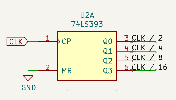
Note that we tied MR line to ground (this reset line is assert high!) so this counter will run continuously and cannot be reset. This has the potential side effect of the first pulse of the divided clock being too quick after changing the clock speed but this doesn't seem dangerous.
This device is also negative-edge triggered rather than positive-edge triggered like many of the other devices in this design. On integration, we will see if that is going to be a problem or if we will have to invert the incoming clock signal to better fit.
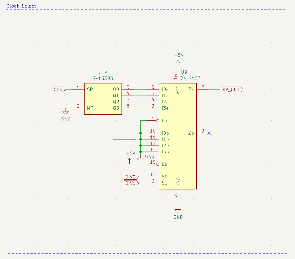
Now we need a way to programatically select which of these signals is our divided clock, using the 2 lowest bits in our control register. For this we will use one half of a 74HC153 4-input multiplexer. In essence, this allows 2-lines to select a single line from our 4 inputs, exactly what we need. The other half of the device is just completely disabled so there is no interference. So our final design is:
Discussions
Become a Hackaday.io Member
Create an account to leave a comment. Already have an account? Log In.