0%
0%
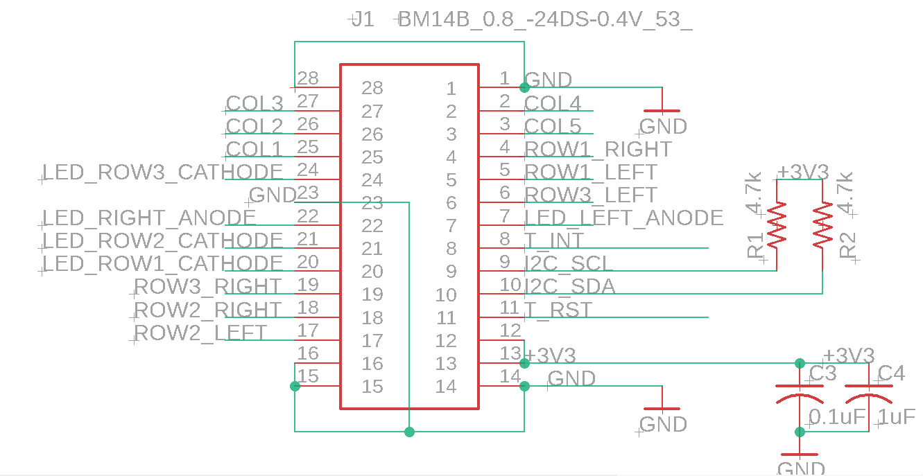
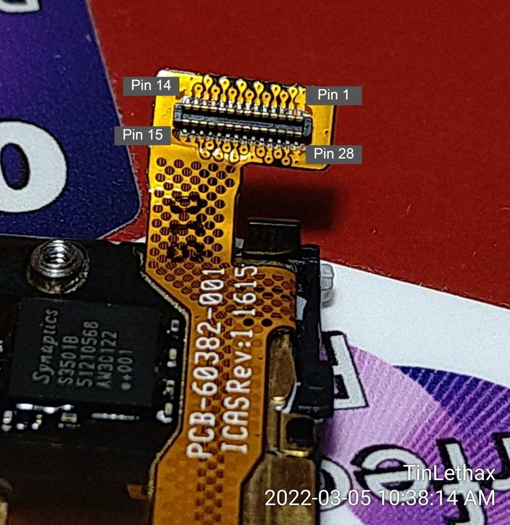
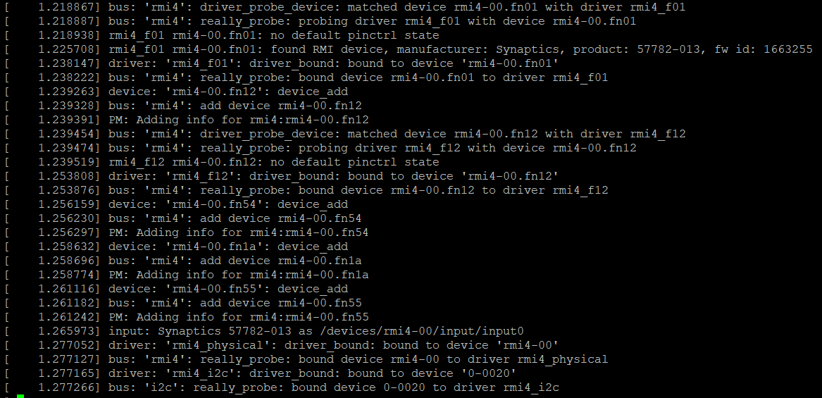
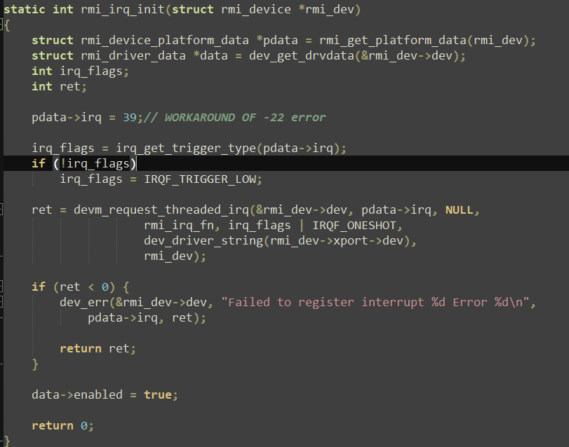
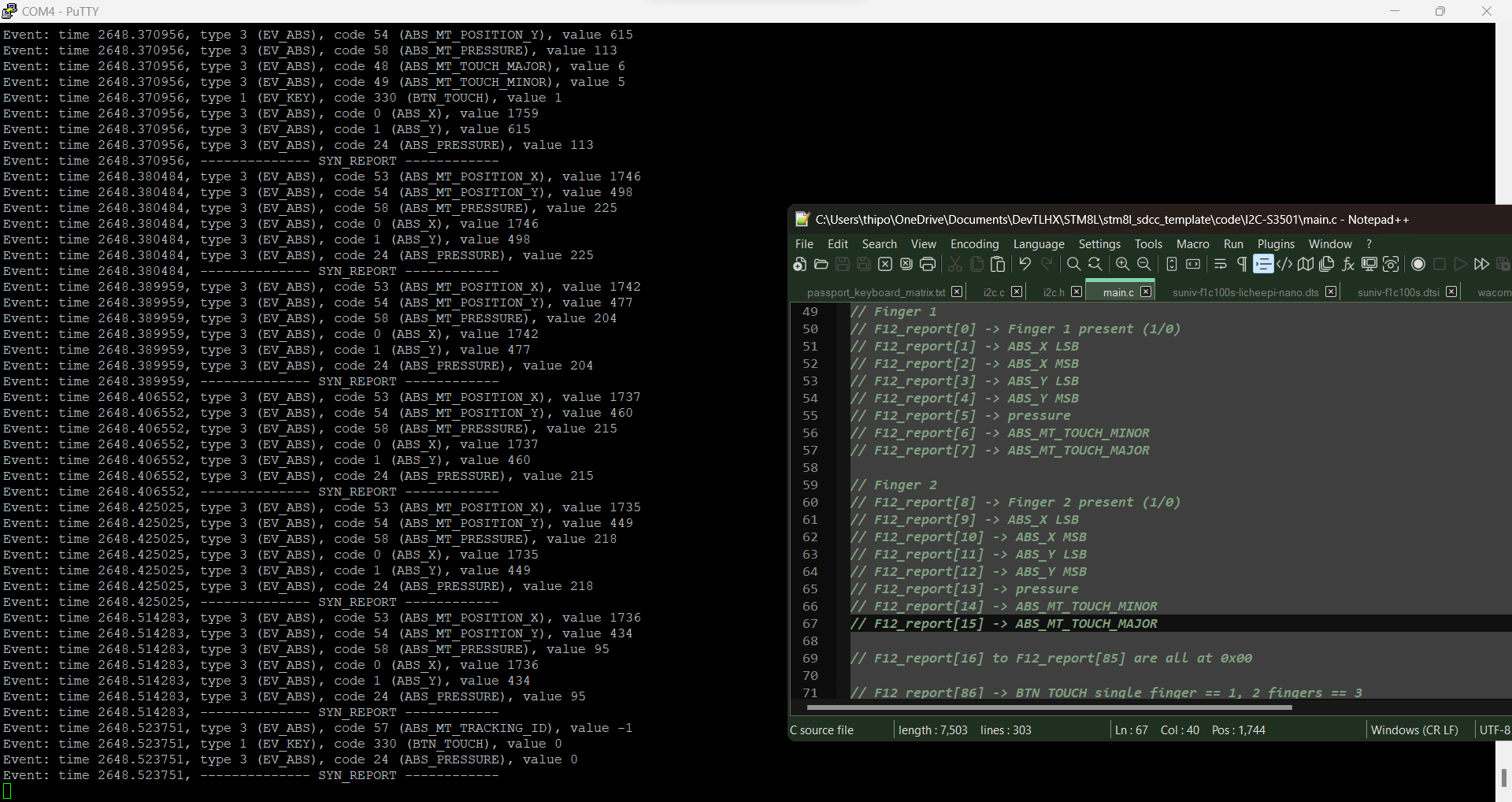
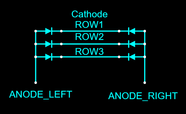
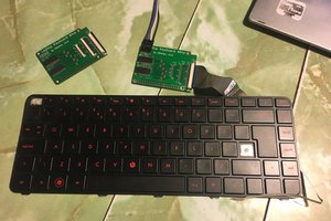
reverse engineering BB Passport keyboard
Ended up sacrificed one keyboard for pinout. Probably one of the worst (layout on) keyboard I've ever seen but I want to use it!
 TinLethax
Become a Hackaday.io member
Already have an account? Log in.
Just one more thing
To make the experience fit your profile, pick a username and tell us what interests you.
Pick an awesome username
hackaday.io/
Your profile's URL: hackaday.io/username. Max 25 alphanumeric characters.
Pick a few interests
Projects that share your interests
People that share your interests


 Arya
Arya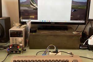
 danjovic
 pdrift86
https://hackaday.io/project/173206-fully-functional-pip-boy-2000-mk-vi
The Blackberry Passport is a perfect fit for the Fallout Pip Boy kit and probably works better than the alternative of using a RasPi. I wonder if the Q30 keyboard could be adapted to still be useful outside of the screen.