 Michael Gardi
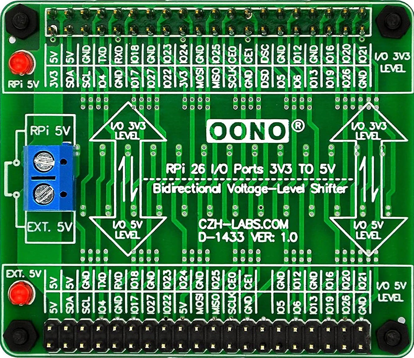
As with my Sol-20 project, the keyboard encoder is expecting 5V while the Raspberry Pi 4 operates at 3.3V. So to overcome this I purchase a Voltage-Level Shifter Module from Amazon. Here is what it looks like.
I am using the Sol-20 header on the encoder and the pinout looks like this.
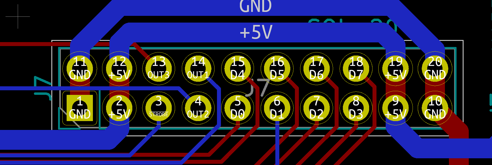
So here is how I wired the keyboard. Note that for the exception of +5V and GND lines which are wired to the 3.3V side or the level shifter, all of the other connections are wired to the 5V side.
| Keyboard Encoder | Raspberry Pi | Description |
|---|---|---|
| +5V | 5V | Power |
| GND | GND | Ground |
| D0 | GPIO5 | Key 0 bit (low) |
| D1 | GPIO6 | Key 1 bit |
| D2 | GPIO12 | Key 2 bit |
| D3 | GPIO13 | Key 3 bit |
| D4 | GPIO19 | Key 4 bit |
| D5 | GPIO16 | Key 5 bit |
| D6 | GPIO26 | Key 6 bit |
| D7 | GPIO20 | Key 7 bit (high) |
| STROBE | GPIO4 | Key ready on falling edge. |
The display has the following pinouts.
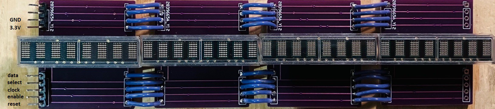
All of the following connections are wired to the 3.3V of the level shifter.
| Display Module | Raspberry Pi | Description |
|---|---|---|
| 3.3V | 3.3V | Power |
| GND | GND | Ground |
| data | GPIO21 | Data Pin |
| select | GPIO22 | Register Select Pin |
| clock | GPIO23 | Clock Pin |
| enable | GPIO24 | Chip Enable Pin |
| reset | GPIO25 | Reset Pin |
Next step, mount everything into the case.
Discussions
Become a Hackaday.io Member
Create an account to leave a comment. Already have an account? Log In.