Giulio Pons
This reuse-recycle project will create a modern object from an old one, so the antique is also a useful object that can be used every day for small tasks and at the same time can make your home or office more beautiful.
Final features
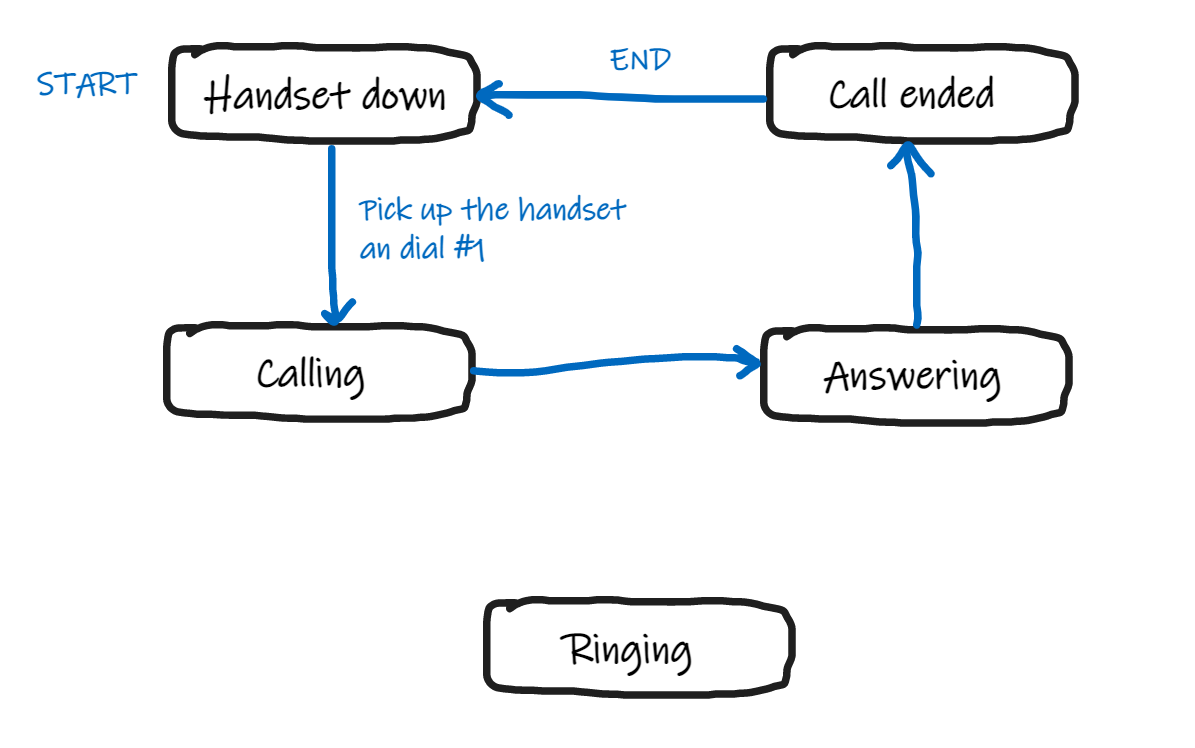
The vintage phone can be used to set an alarm by calling a number that represents hours and minutes, or you can dial a specific number to get current time and date, or call another number to hear meteo forecasts, and so on...
Answers are heard by the user throught the handset, and requests are made by using the old rotary to dial commands.
I'd like to create a project that can be spread around, once the Vintagephone is assembled, it should be easy to be used also for non tech people as it once was calling with a rotary phone.
For tech users it would be easy change mp3 files with custom messages and write code to create new services.
Phonebook
Updated list of numbers you can dial to get messages:
#1        - tell the current time
#12       - set an alert after 2 minuts
#13       - set an alert after 3 minutes
...
#1999     - set an alert after 999 minutes
#11000    - set an alert at 10:00
#1-HH-MM  - set an alert at HH:MM
#2        - delete alarm
#9        - ring bells (for test
#21       - restart Wemos
#22       - adjust the time of Wemos from internet
#22-HH-MM - adjust the time manually to HH:MM
#22-YYYY-MM-DD - adjust the date manually to YYYY/MM/DD
#23      - activate AP to set the SSID/password to connect to wifi,
           latitude, longitude and utc for weather
#24      - play heads or tails
#25      - say yes or no
#4       - meteo forecasts (thanks to https://open-meteo.com/)
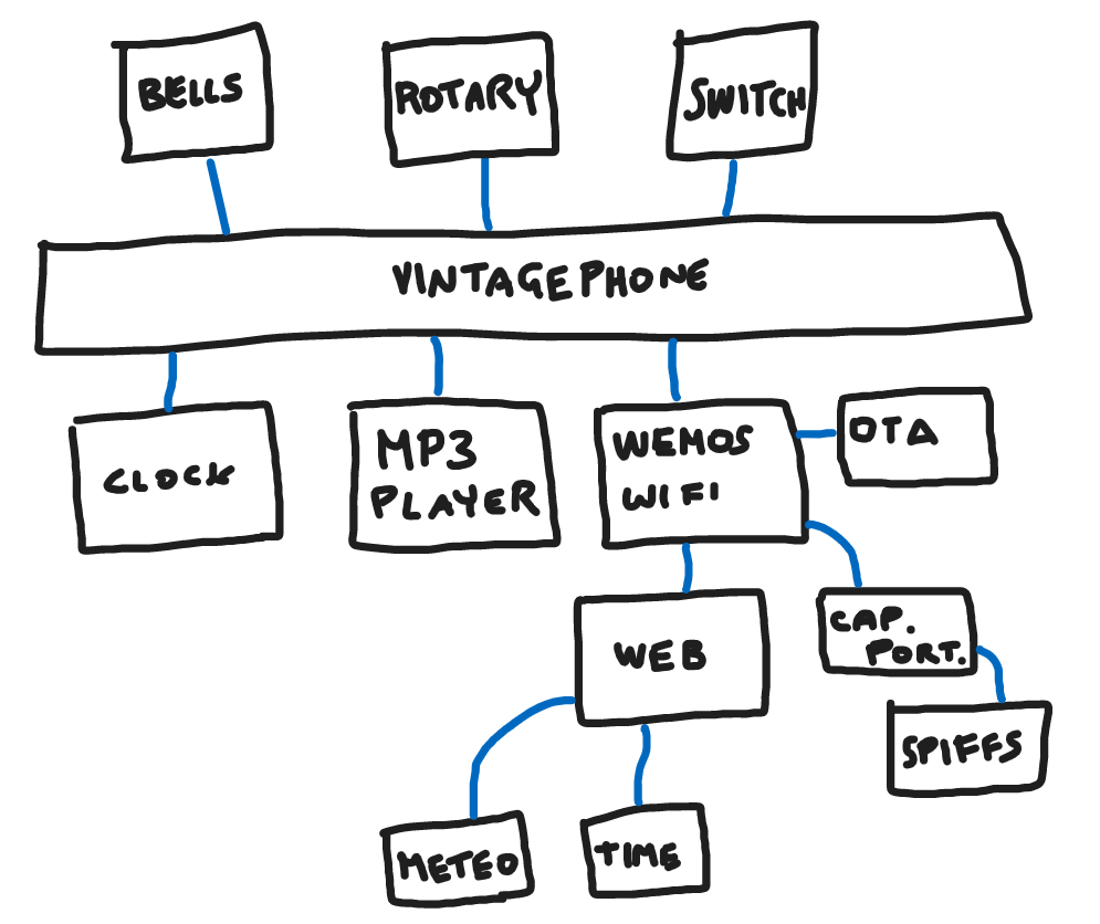
Reused components and modern parts
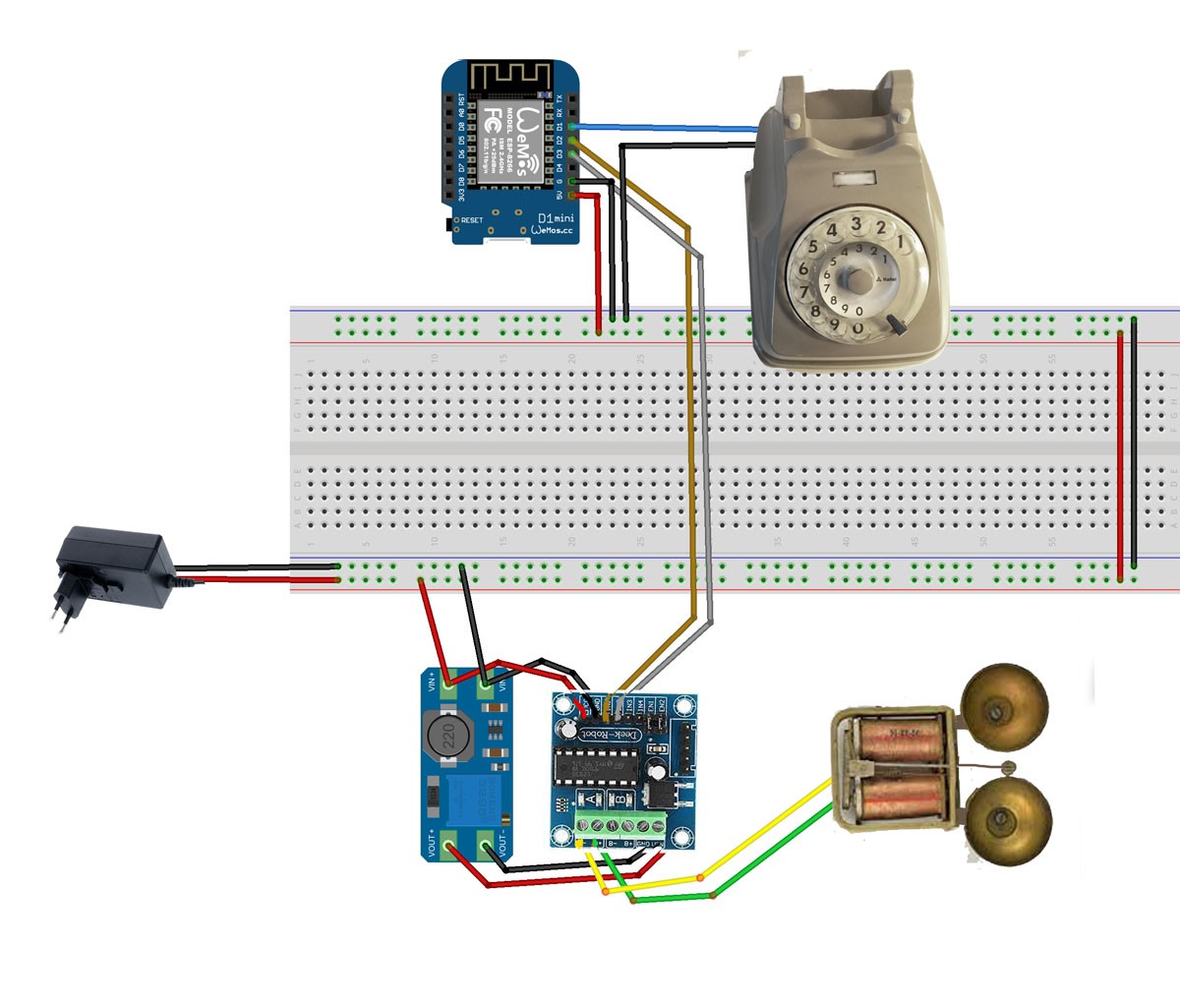
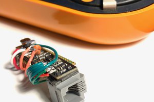
1) Rotary dialing encoder
I've used the vintage rotary composer to dial numbers, numbers dialed become commands for the microcontroller
2) Original bells for a vintage sound
I've powered the original bells and used that vintage ring, boost up converter DC-DC is needed to transform 5V to 12V. And also an L293D motor shield is used to alternate voltage to the bells to make it ring.
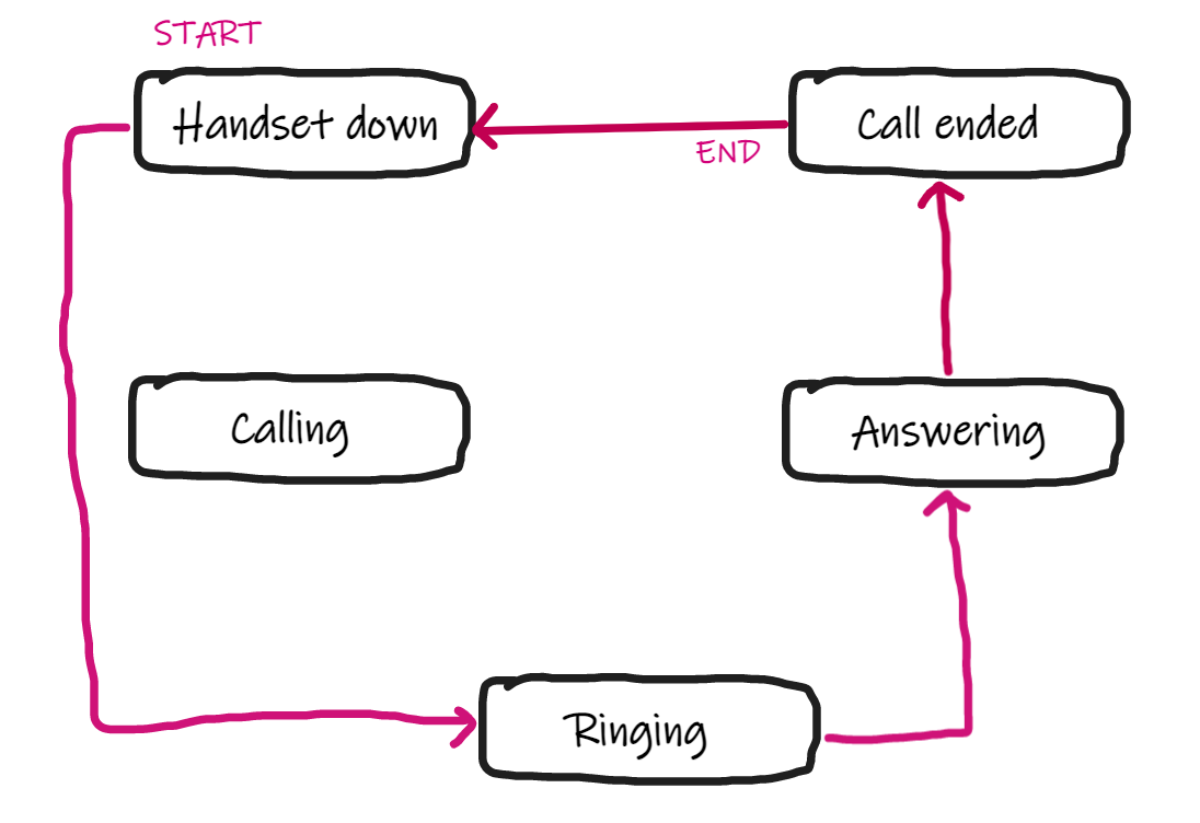
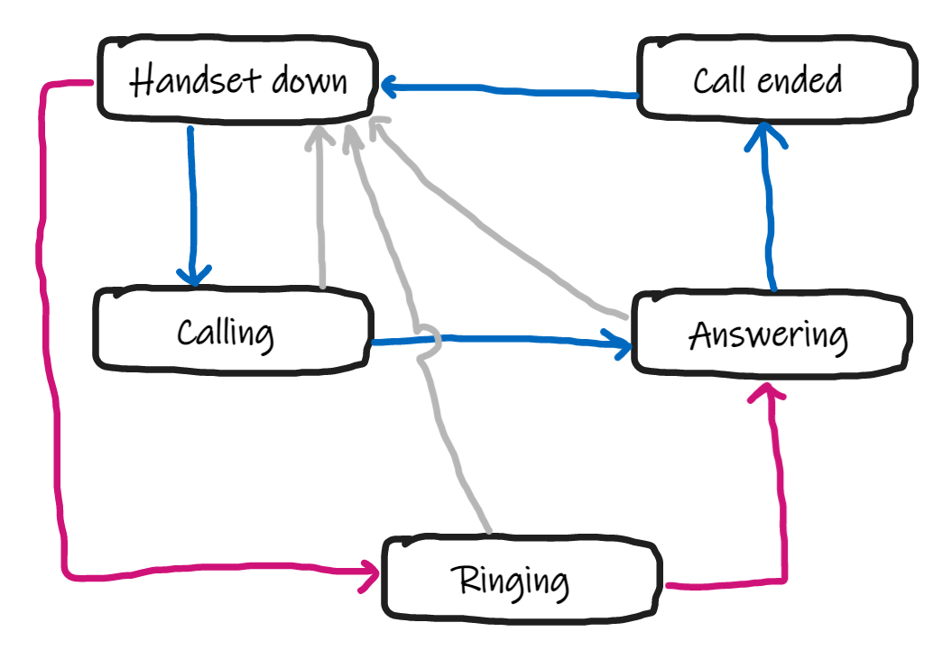
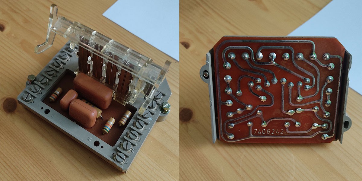
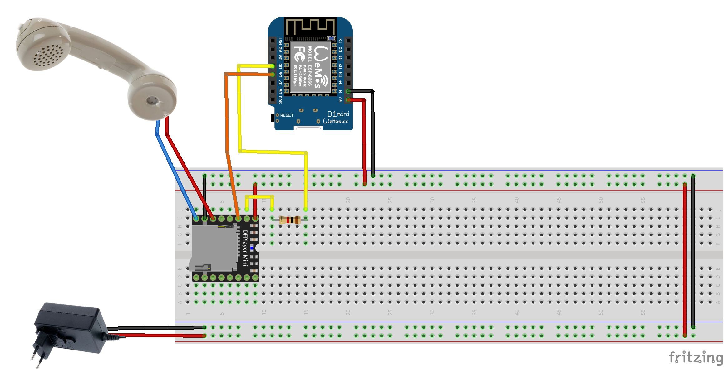
3) Vintage handset and switch
The handset is used to listen the messages. The two white buttons under the handset when it is hangup are still used as a switch.
4) Wemos board
It's my preferred board to make "Arduino" projects because it provides also access to wifi, if internet access is available there will be some functionalities, such as local meteo informations, autosetting date and time, more to come (suggest your ideas!).
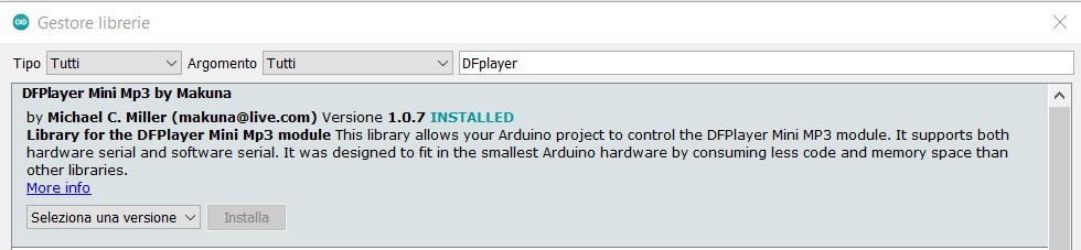
5) DFplayer / micro SD card
The mp3 player with micro SD card provides audio samples for all the messages speaked in the handset, this means, number samples, meteo keywords, error messages, etc (no text to speech software is used).
6) Power supply
All the stuff has been powered with a 5V, 3000 mmA adapter.
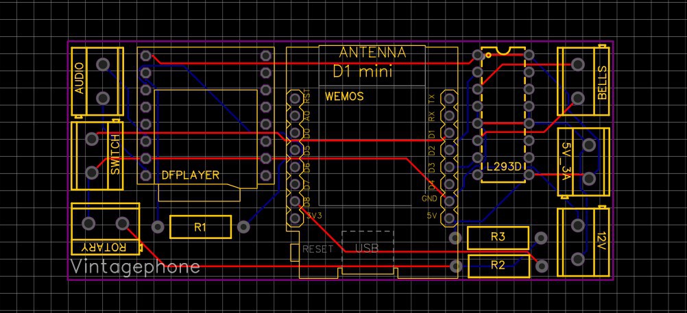
Complete schema

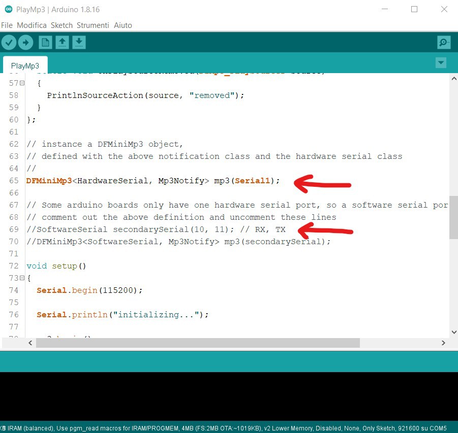
Code project available on GitHub
The whole code of the project is published on Github here:
 Here is a small script that ring the bells a few times and then makes a pause. It will repeat until someone picks up the handset.
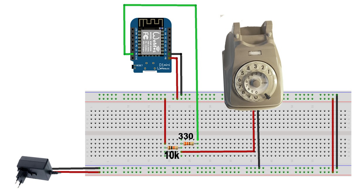
 Steph
Steph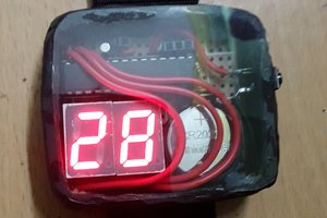
 Brainy.Baboon
 jaromir.sukuba