 kelvinA
I did some looking into the printer series' that this scanner is used in, and all but one of them has "optical resolution: 2400dpi". Now this is actually really high, as resolutions in the datasheets that exist online are 200, 300, 600 and one or two 1200dpi. I looked into a handful of other sensors on AliExpress and the printers that they're used in have a 1200dpi scan.
The one used in #Magic Frame : Turn Everything into a Touch Area had 2700 pixels. For 216mm of scan length, a 2400dpi scanner would have at least 20,410px!
Thus, I looked for a 2400dpi CIS chip, assuming that HP wasn't going to invent their own. The only thing I found was the AMIS-722402, with datasheets online (with the sharpest looking to be from Arrow as a PDF download).
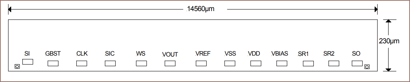
14.56mm wide per sensor chip means that 15 sensors would be put together to get over 216mm, resulting in 218.4mm of scanning length and 20,640px.
By looking at other sensor datasheets, one of the things I noticed is that the communication protocol is rather standardised. There's a pin that starts the scan, a clock signal and, some N number of cycles later, the "video out" (aka sensor data) gets read 1 pixel at a time.
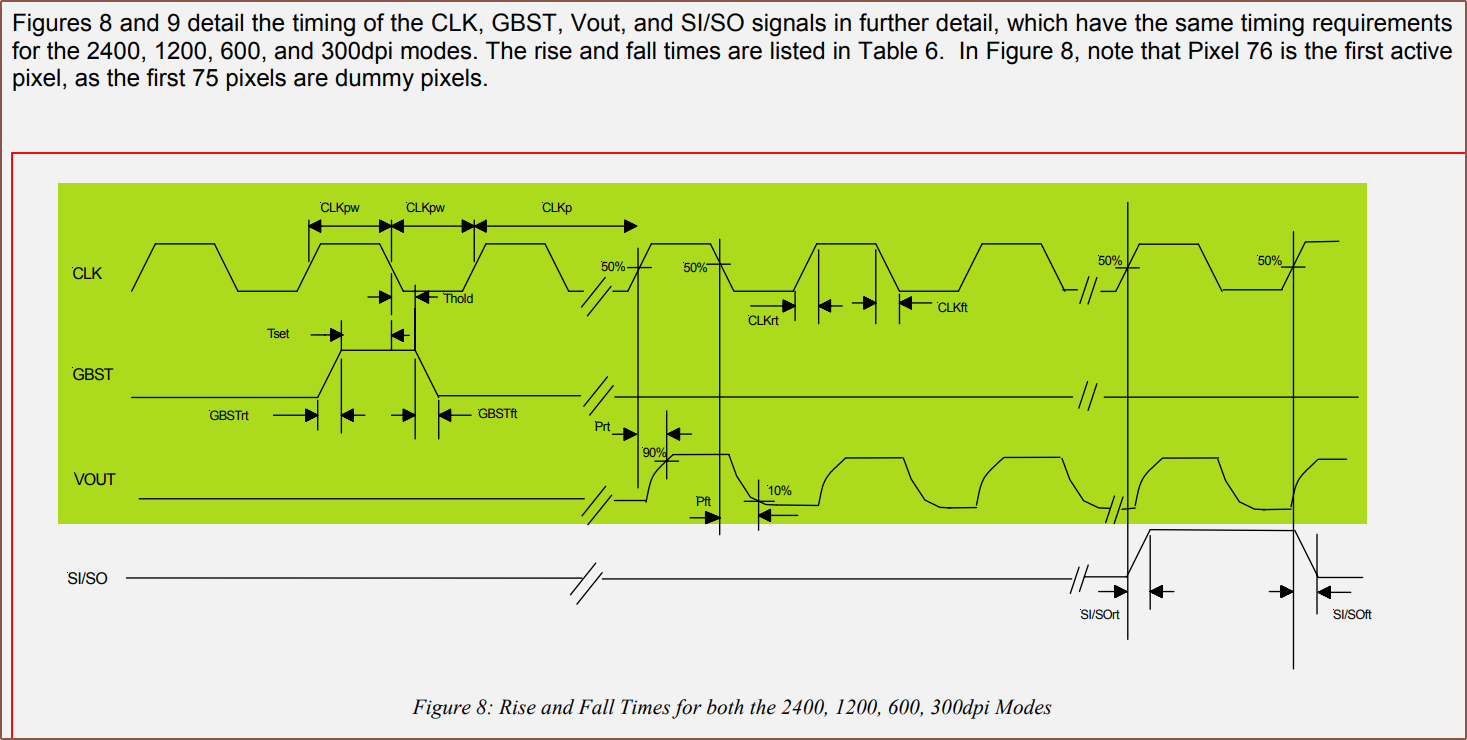
For this chip, the clock is typically 2.5MHz but it sounds like the engineers expect the fastest, 3MHz, to be used more.
So I was thinking to myself "That's all great and all, but shouldn't there be like some kind of examplar circuit in here?" and there was one at the back. I think I'm onto something:
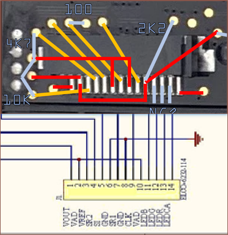 I looked at the pinout here and many of them lined up with the pinouts determined in the past. One of them that was close but not quite was the assumption of "GND but not connected directly to the other GND" pin 3, and this is why:
Technically, the pin can accept 0V, but it's actually expected to use 0.35V and determines the black-level voltage:

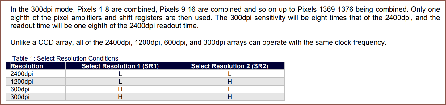
Then there are select pins that determine how high a resolution is scanned. Lower resolutions bin pixels together, making them proportionally more sensitive.
I connected the LEDs and found that Pin14 is LED Positive. I expected the entire white section to illuminate, but it's only a strip next to the lens array. I also found out that
- Red: Hits the set current limit of 200mA and thus drops till 2.17V
- Increasing the current limit didn't seem to make the LED brighter nor increase the voltage, so I tried a lower one.
- 2.2V was at about 150mA and slowly climbing
- 2.1V was notably dimmer, and 2.0V dimmer still.
- Thus, it sounds like I'm going to need a resistor on LEDR.
- Green: 5V at 107mA
- Blue: 5V at 166mA
Discussions
Become a Hackaday.io Member
Create an account to leave a comment. Already have an account? Log In.