 Shawn Alfaro
This little guy was donated to me with no battery and in unknown working order. I was able to get it powered externally and downloaded the app. after many attempts and resets, it failed to connect to the app. The app is its primary control input and without it, it is just a paperweight.
A teardown without pictures occurred. I have another coming in the mail and I will take pictures of that teardown.
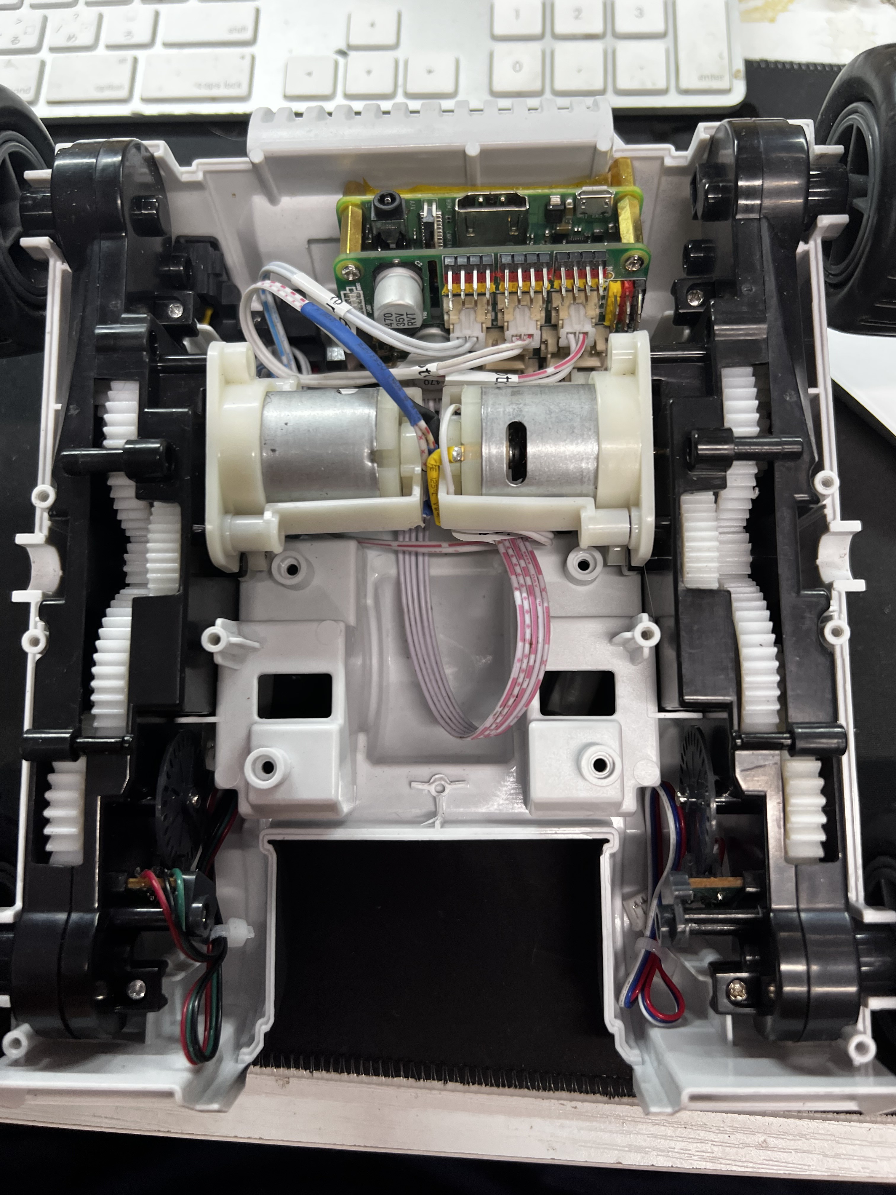
The teardown notably revealed 2 PCBS with a L298N motor driver on one for the 2 DC motors that drive the wheels, with an ARM chip, and an unpopulated header (5v, DATA, CLK, RST, GND)
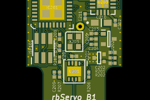
The second PCB in the head had an unpopulated labeled UART header, an unpopulated labeled Debug header, an AIT8328D IC, an unpopulated SD card spot (which has been populated but unused so far) a AP6131 wifi chip with antenna, a camera slot and a header for the camera cable that connects the two PCBs together.
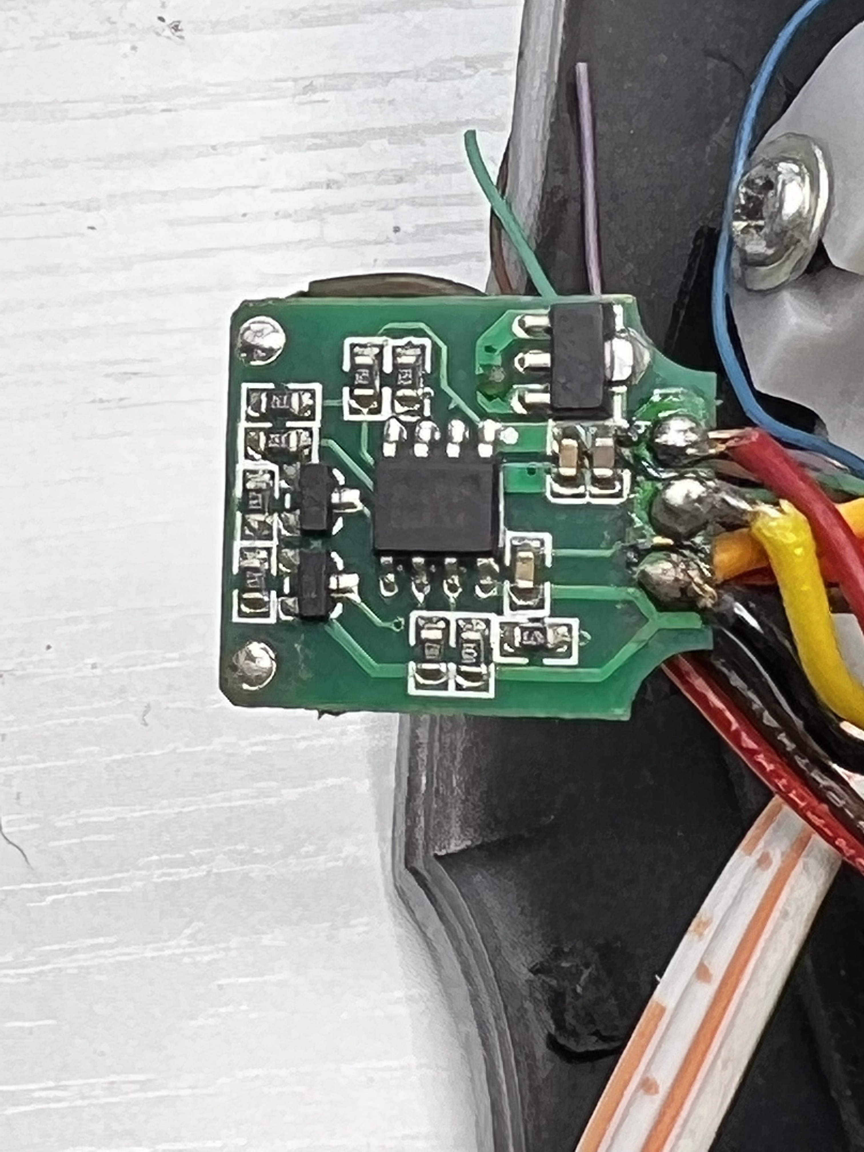
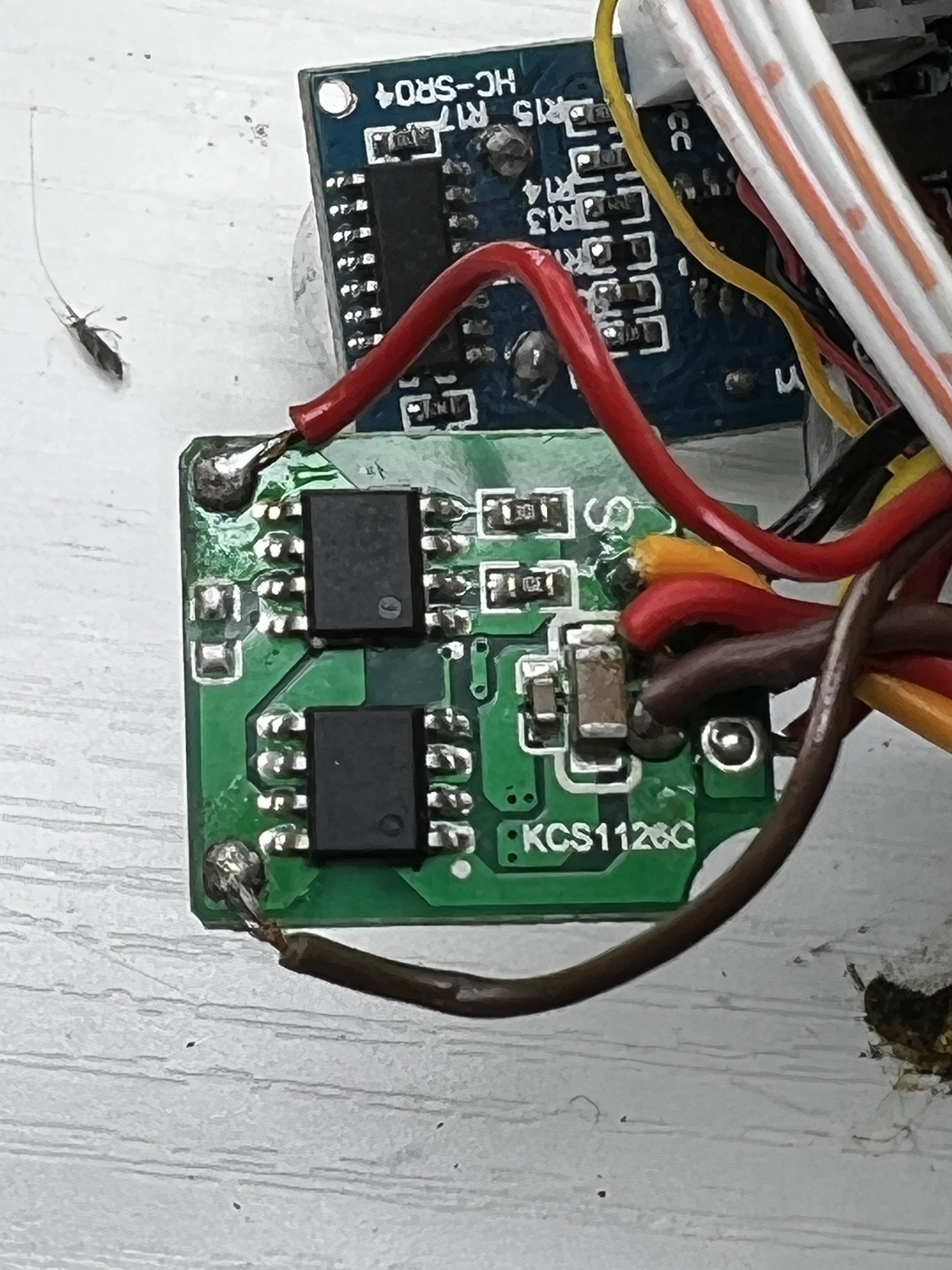
All motors that move the arm are geared DC motors with potentiometers, including the gripper, wrist, elbow and shoulder. These are basically dumb servos as the driver chips normally found in hobby servos are remotely on the original motor driver PCB instead.
(most of the more expensive robot RC toys use this system of geared DC motors with potentiometers and all 5 wires go to the controller board in the toy)
The gripper and wrist have removable gears and i managed to scatter them all over my bench and will use the new one to figure out how to reassemble them properly.
Anyway this is what I have accomplished so far: (mistakes notwithstanding)
- completely tear down the bot and identify major components
- install Raspberry Pi/Hat Assembly in a discrete place in the base
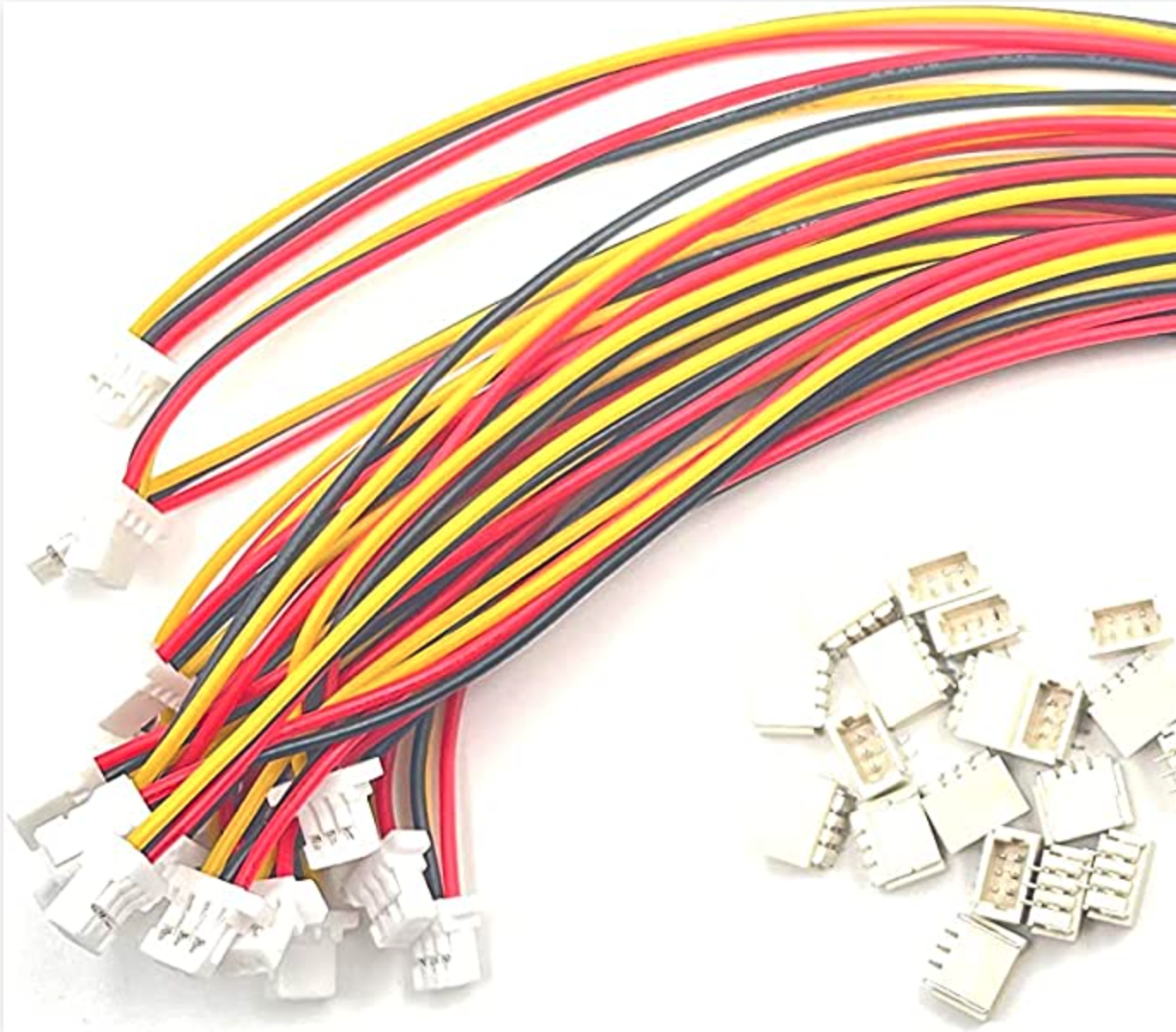
- rewire wheel motors with new wires and JST-XH connectors to match motor driver board
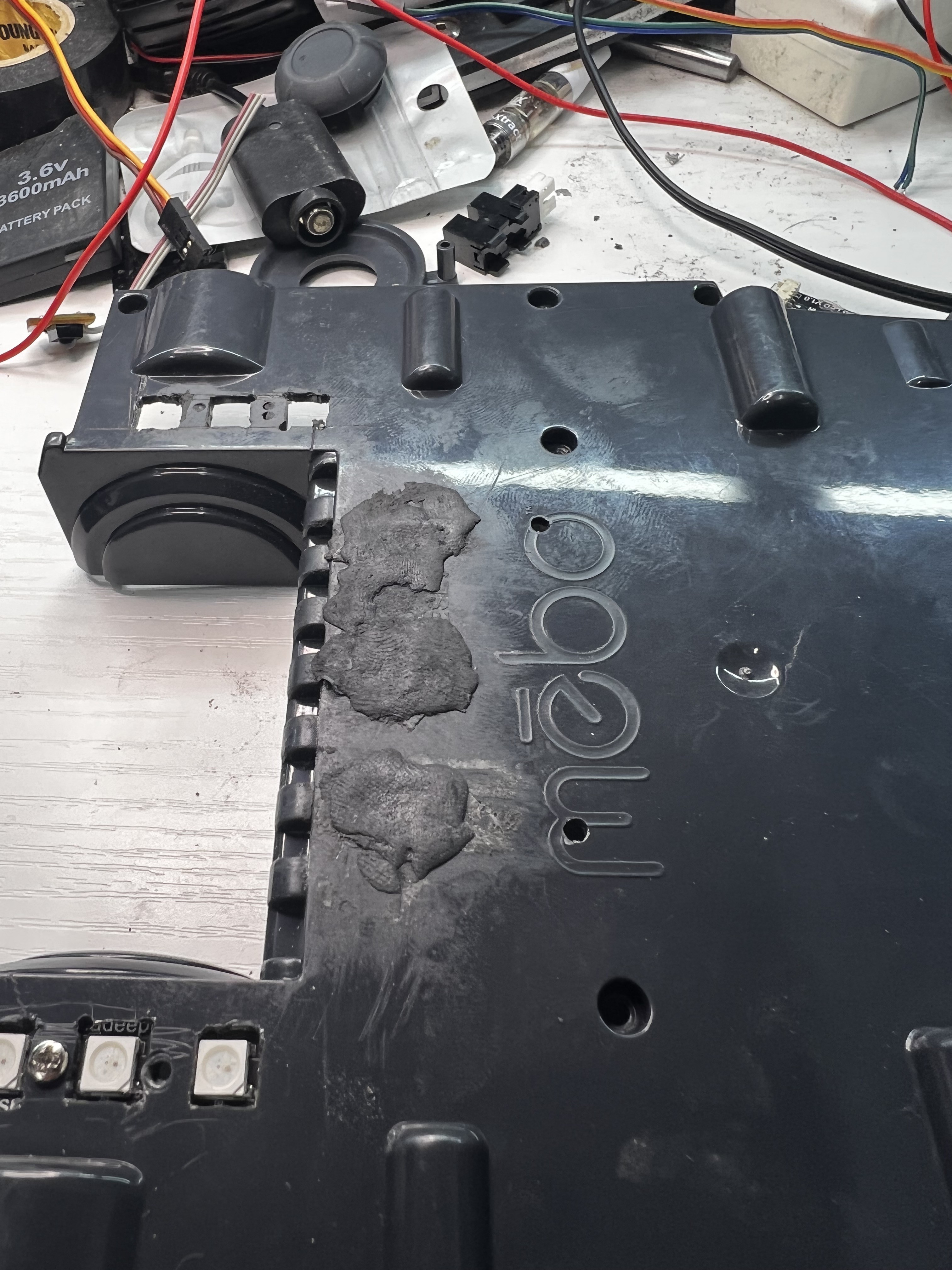
- rewire power switch with new 18650 x2 battery holder in the old battery box
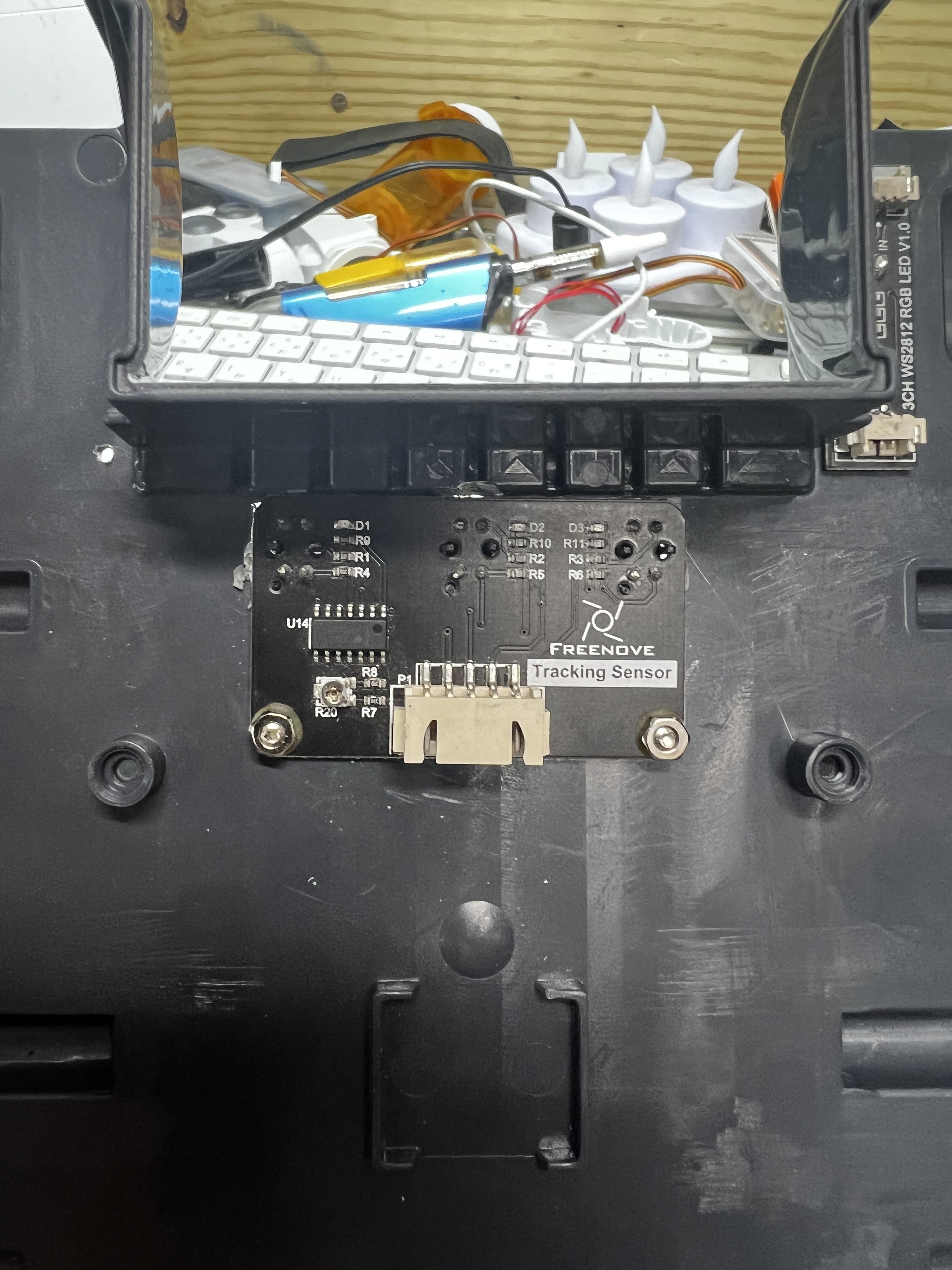
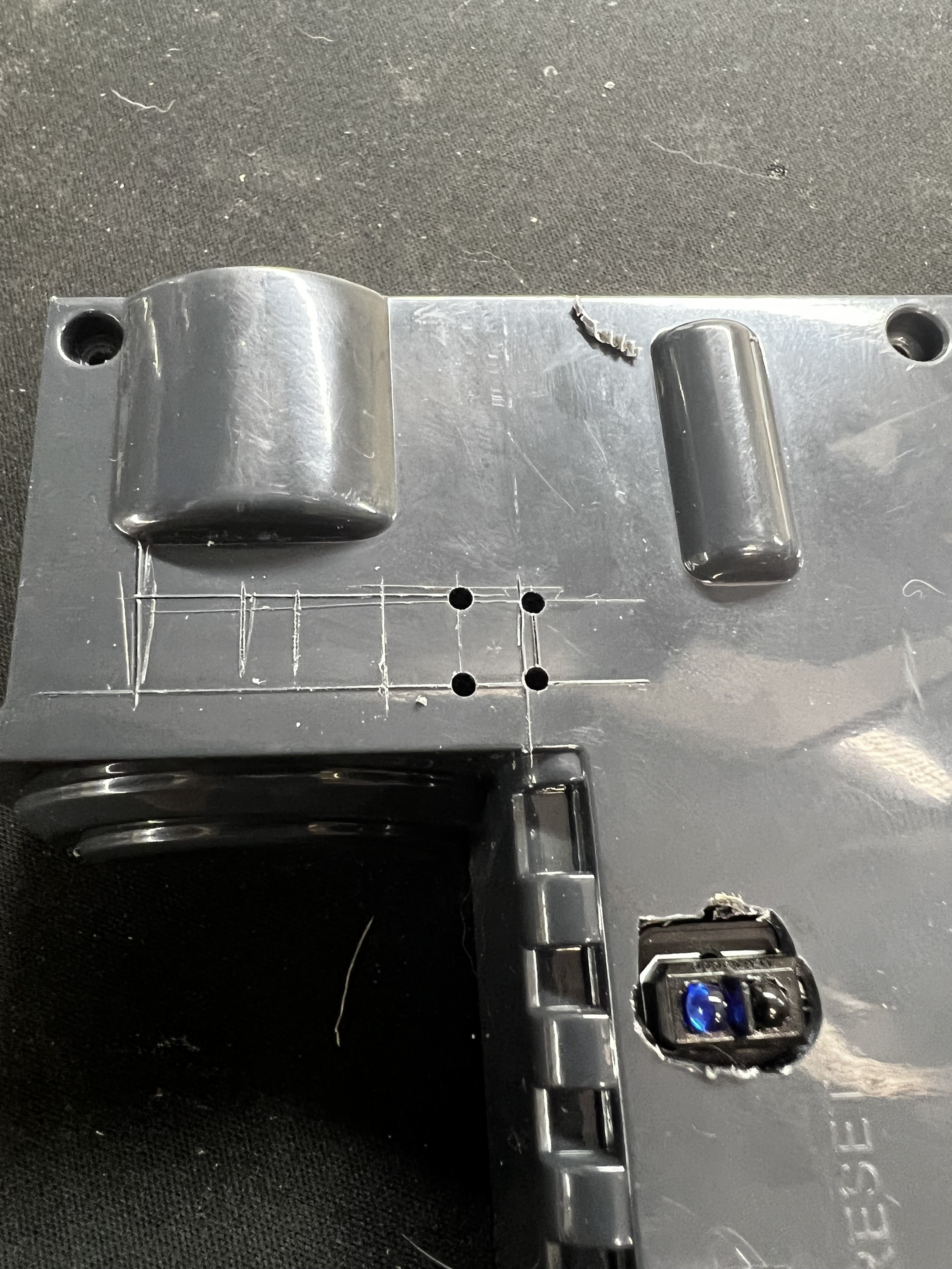
- install line follower sensor
- remove all original wires, boards and camera (all set aside for possible future reuse)
Things to do:
- wire donor servo boards to the geared DC motors in the arm so that the 5 wires can go to regular 3 wire servo plugs and plug into the motor hat.
- install a modified USB webcam in the head to replace original cam. ( Makerbot Replicator webcam modified with original Playstation Eye lens assembly, has manual 2 position focus)
- install new RGB light ring for cam.
- possibly install small servo to switch the lens focus position
- install WS2812 RGB LED bars (came with hat)
- install Ultrasonic sensor (came with hat)
- try to make all new hardware installs as discrete as possible to maintain original stock look.
- try to access the original board either via UART or DEBUG header and dump original firmware or attain root access. (I've never done this before so I don't know if ill get to that but I would like to so i can gain full control of the bot without heavy modification)
I will post pics of the progress so far and of the original PCBs in the immediate future.
 RasmusB
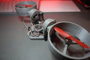
 Saul
Saul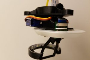
 Daren Schwenke
 Timo Birnschein