 Phil Wright
I am designing a video driver for my upcoming computer. So I have a MX045HS which outputs a 25.175 MHZ signal which is needed to generate a 600x480 resolution VGA output signal. Connecting the crystal output to my trusty oscilloscope gives a pretty poor click signal...
 Using the reference source on the oscilloscope I can see that the poor signal is not a measurement/probe problem...
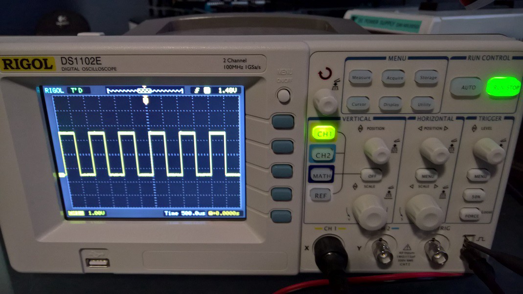
I assume it is normal for a crystal to have such a poor signal. What is the standard way to improve this to a nice square wave? A standard circuit you can point me to?
Discussions
Become a Hackaday.io Member
Create an account to leave a comment. Already have an account? Log In.
So, Phil, this has got me thinking about your clock distribution in the larger system. Especially on the clock lines, you need to be careful about proper layout and signal integrity. The rule of thumb is that you need to treat wires (traces, etc) electrically longer than about 1/6 of the rise time of your logic as transmission lines, and terminate them at either or both ends. The rise time of a 74HC gate is about 5 ns, so that is equivalent to 1.5 meters in free space ( maybe 2.25 m in a common cable). 1/6 of this is is about 25 cm worst case. So, if any of your lines total length (including distribution between boards, trace length on the boards, etc) exceeds 25cm, you may run into distorted waveforms like this on your clock lines. Things get more complicated/worse if you have a tree or multi-endpoint structure for the clock connections.
For most signals, if you run into trouble with long traces and distorted waveforms, you can just slow the system down, and wait for any transients on long lines to damp out before the next clock cycle. On a clock line itself, you don't have that luxury, since circuits on the clock line are typically edge-triggered and can get double (or triple or more) triggered if you have reflections on the line. For counters or sequencers or anything like that, it's a disaster. You can mitigate this somewhat by slowing down the clock edges, again at the expense of overall speed. But even that isn't trivial to do right.
I might suggest finding a copy of High Speed Digital Design by Johnson and Graham
https://www.amazon.com/High-Speed-Digital-Design-Handbook/dp/0133957241
You might get lucky and find it at a local library. I found a paperback online for $25. If you're not really familiar with the concepts, you will easily save this much while building a 74xx 32-bit CPU. I resisted buying this book for years, trying to learn the pieces through random app notes and web sites, and it was a serious mistake. Oh, and the "high-speed design" the title refers to is roughly 10 MHz and above including designs with wire-wrap or on PCBs with SSI/MSI parts like you are designing with. It's a short read - I poured over it thoroughly and it only took about a week and a half, but it changed my life :-)
Chapter 3 covers probing issues like you ran into above.
Are you sure? yes | no
As a beginner I don't know what it is I don't know! So whole new areas of consideration open up. I will certainly get this book.
My first goal is just to get it working, even if only at 100 Hz! Then increase the speed and see what happens.
The design is deliberately very modular with lots of small boards and using connecting cables to route data. Having bundles of 32 wires interconnecting boards is never going to be great. But does mean that once a minimal version is running I can update the design and reuse 90% of my boards. Just stick a couple of extra MUX boards in there to connect up some more functionality and off we go.
Thanks for the feedback.
Are you sure? yes | no
I think @Yann Guidon / YGDES covered all the major points. Your oscillator is probably fine. I suspect the breadboard and long wires (especially on the probes) are the real culprits here. You might also want to add a bypass capacitor close to the oscillator package if you don't have one - there are bypass caps inside, but more won't hurt.
Just because I happen to have a homebrew VGA generator and a 100 MHz oscilloscope on my desk at the moment, here are some reference waveforms. First, with the normal scope grounding alligator lead (~ 15cm long) clipped to the ground plane near the oscillator:
And without the ground lead, with the probe tip ground ring held right to the metal oscillator case:
Just the short ground lead is enough to add those wiggles; extra length around will only make it worse. You can check out the layout and ground-plane construction in #PIC Graphics Demo
EDIT: I forgot to mention, I think the oscillator is the same part number. Mine is one of these:
https://www.digikey.com/product-detail/en/cts-frequency-controls/MXO45HS-3C-25M1750/CTX761-ND/1801876
which is an MXO45HS. Mine is in a smaller 8-pin case, while yours looks like it's in a 14, which is strange - maybe they make both sizes under the same base part number.
In any case, pull the ground lead and witches hat off your probe and hold it right on the pins/case of the oscillator without any parasitic breadboard or wires, and you'll probably see a nice clean square wave. The rounded edges above could be the scope bandwidth. I'll grab a pic on the faster scope when I get a chance to drag this board down to the lab.
Are you sure? yes | no
Thanks. Reassuring to know it is working correctly.
Are you sure? yes | no
Still, considering your setup, the waveform is not too bad.
Are you sure? yes | no
There are many, many factors that explain this waveform : don't worry, but also learn :-)
VHF waveform catpure is a black art, requiring the right tools and the right knowledge.
Among others :
* Your Rigol is bandwidth-limited to 100MHz, that is, 1/4 of the measured frequency : that can deform the waveform, since 100MHz is for a sinewave, not a squarewave.
* you use long leads, with crocodile clips, on a not-VHF-suitable circuit, there are capacitances and incuctances everywhere !
* Did you check the input impedance ? Did you set your probe to 10x ? 1x is usually limited to about a few MHz.
* Canned oscillators indeed have a "not square" output. That's not really THAT important as long as the transitions occur at the right places.
* BTW I usually add a series resistance, like 50 or 100 Ohms, between the osc output and the CMOS input, to make a cleaner waveform. Maybe your circuit is not loaded, and this also influences the waveform...
Are you sure? yes | no