 Phil Wright
Just because the register control board is green doesn't prevent us from testing it. The purpose of this board is to take information from the current instruction and use that to generate individual select lines for the 16 registers in our register file.
Many of the RISC-V instructions specify two registers as the source of values for the operation. These are called rs1 and rs2 in the ISA description. Here is the specification for the ADD and SUB instructions as an example.
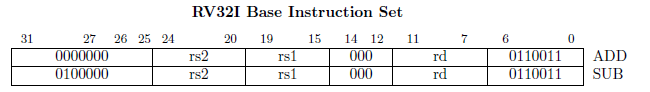
Our board will take bits 15-18 (4 bits) and 20-23 (4 bits) as inputs. Notice that the instruction above specifies five bits allowing 32 registers to be selected from. But we are implementing the RV32E specification and not the full RV32I version. The RV32E spec only supports 16 registers, so we can simply ignore the most significant bit as the top 16 registers will never be referenced.
We assume that the code running on our CPU is valid, a commercial system would have checking for invalid instructions and accessing registers out of range. We are not going to bother with that, if your code is wrong then good luck with strange actions occurring!
So, bits 15-18 arrive at the board representing the rs1 field and are decoded into 16 output lines with only the matching register line selected. In practice, we have implemented the register storage boards to output on a low value. So 15 lines will be high and the matched register number will be set to low.
We can see this being tested and working below...
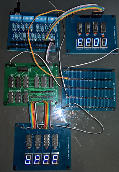
The top left shows our fixed value input board. It has a value of 01 as shown by the output on the top right hex display board. The green board outputs 16 lines and the hex value of that can just about be seen as BFFF or 1011111111111111 as binary. Starting counting at zero it has indeed selected the first line if you start count from the left-hand side. I have tested it with all 16 input values and it does indeed select the correct bit appropriately.
You might be surprised that it counts from the left and not the right side. Well me too and it turns out I make a snafu on the design. When I reorder it in blue I will rotate the output headers 180 degrees so it matches my expectations. It is not a big deal but as I want to reorder in blue anyway I might as well make the change. It will make wiring slightly neater.
Bits 20-23 from the instruction provide the rs2 field and are decoded in exactly the same way and simply output on a different header. The final functionality is similar but a little more complicated. Many instructions use the rd field to specify a destination register that should be written to with the result of the operation.
So we need to decode from a binary number to 16 values. But this time we also need to invert the outputs because writing to a register really does need to be high for a write and low for ignore. Simple enough we just add a bunch of NOT gates. But we also need to ensure we only write when the CLK occurs and the WRITE line is defined. Only some instructions need to update a register and this decoding will set the WRITE line. We only want the update to occur synchronously on the next CLK signal. So, we AND the CLK and WRITE and only when both are set do we enable the outputs for write lines.
This sounds fine in theory. Time will tell!
Discussions
Become a Hackaday.io Member
Create an account to leave a comment. Already have an account? Log In.