 Christoph
This probe's attenuation isn't very accurate, especially without termination on the scope end. I've had a look at what the termination does.
The setup
Probe in a fixture, with one SMA coming from a signal generator, and the other going to the scope (channel 1, unfortunately hidden behind the probe. The fixture looks just like the unused one to the left). Probe output also goes to the scope (channel 2):

Probe is supplied with a bench PSU set to 5 V. The other fixture shown in the picture is not in use.
Signal generator
- 1 MHz sine
- 5 Vpp
- zero DC offset
- High-Z load
Scope
- time: 200 ns/div
- vertical: 1 V/div
- Channel 1: input from signal generator, no termination
- Channel 2: FETProbe output, through a T, to add a termination resistor later.
Results
If there's no termination, channel 2 must be set for a 10x probe. Here's the result:
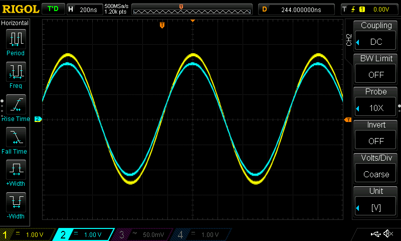
That's an error of about two subdivisions, or 0.4 V (-16% with regard to 2V5 peak). Not so pretty - we'd like the two signals to have the same amplitude. Or at least a little less bad.
With termination and channel 2 set to 20x:
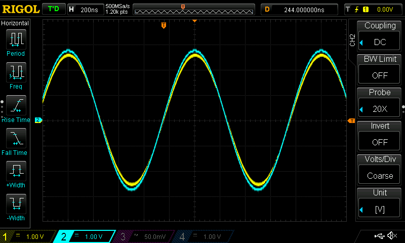
Zooming in, I get about 1 subdivision of overshoot, or +8%. That's better.
More expensive professional probes are of course better in this regard, and I'll try to find ways to improve this one. It's definitely a good start, considering that it's cheaper than the passive probes that come with an entry level scope.
Further remarks
Also note that the probe doesn't really care about its input signal's DC offset. Since the input is fed straight into a series capacitor, it's stripped from its DC part. That's why it can handle signals that swing below ground, as in this case (signal generator is set to zero DC offset).
The probe's output filter also begins with a series capacitor, so the actual output to the scope can also swing below ground even with a single +5V supply. It's inherently AC coupled, so it doesn't matter if the scope is set to AC or DC coupling. And no, we cannot measure DC signals with this thing.
Discussions
Become a Hackaday.io Member
Create an account to leave a comment. Already have an account? Log In.