 Maximiliano Palay
As shown in the concept image, the prosthesis was to be manufactured using a 30x30 mm aluminum extrusion as the main structure, and 3D printed components around it to hold everything together. This had numerous advantages, such as ease of assembly and disassembly, a large amount of mounting points (or rails) over the four sides of the aluminum profile. These are key points for working on a prototype.
The main disadvantage of this concept is volume. The profile takes up space which could be more efficiently used, distributing the greater surface and not having it on a column shape would enable placing of electronics on the inside of the prosthesis, rather than mounting everything around the extrusion. The latter would result in a bulky prototype.
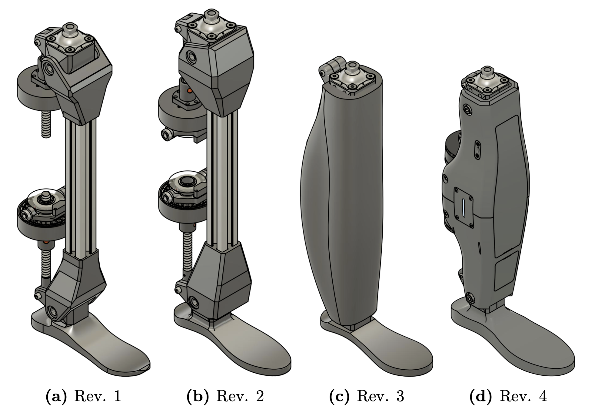
After a couple of revisions (Revs 1 and 2), this initial concept design was halted. It wasn't just about the volume, it would be very difficult to make it look good too. Revision 3 was all about "let's see what I can come up with in a few minutes, dreaming about fully printing it in 3D". This resulted in more of a leg shape right off the bat. Sketches of a design were then paper-drawn, and a more though out model was created. This generated the fourth and final revision.
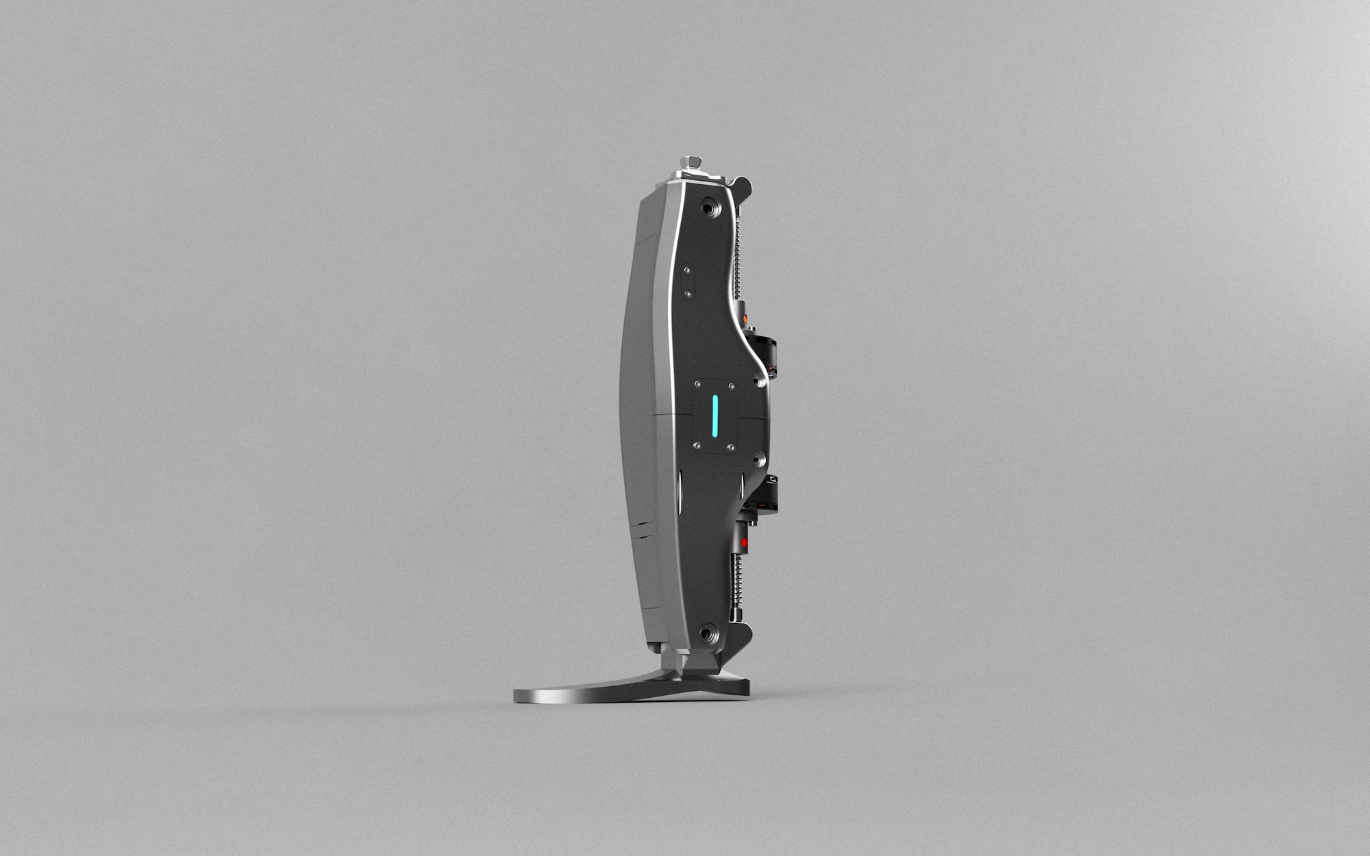
There's a myriad of design aspects, issues and solutions to talk about. I'll highlight a few things. The prosthesis begins with a pyramid adapter at the top that enable it to interface with existing prosthetic sockets. The main body is split in half since the design phase, because the 3D printer to be used does not fit the whole body at once. The foot requires much more design to provide proper damping and suspension, in this case, the foot is just support. This project focuses on creating a functional prototype, and the foot is left for future improvement. The electronics are held inside the body inside two frontal cavities, which are enclosed by covers that are held in place using magnets. This allows for the covers to be easily removable without any tools. This is a plus for showing and explaining the project. The internal electronics cavities have several mounting holes to attach the components with screws.
The whole assembly is over 150 pieces.
The knee and ankle were designed in a "block" fashion. These are kind of like rotating blocks over an axle, hence their name. In the exploded view animation, both blocks are shown to be cut inn half. This is to enable a more symmetric fabrication and have the layers aligned with the direction of greater stress. Each block's halves are joined together by M3 screws and nuts.
Used bearings are 608 for the joints axes and 625 for the motor mounts. The axes are M8 and M5 screws respectively.
The model has two lateral panels with LEDs to communicate the prosthesis status to the user. And you can't deny these are aesthetic A*! The LEDs to be used are RGB, placed in combination with a diffuser that "shapes the light" to its slot form.
Discussions
Become a Hackaday.io Member
Create an account to leave a comment. Already have an account? Log In.