Close
0%
0%

3D PRINTED PORTABLE WIND TURBINE

A small Portable Wind Turbine, mostly 3D printed!

Public Chat
Similar projects worth following
A wind turbine mostly 3D printed , which houses a BLDC motor as an electric generator. Foldable and no larger than a 2L soda bottle. Simple to replicate and with a low manufacturing cost. CAD, STL and how to make it included.
Creative Commons License
This work is licensed under a Creative Commons Attribution 4.0 International License.

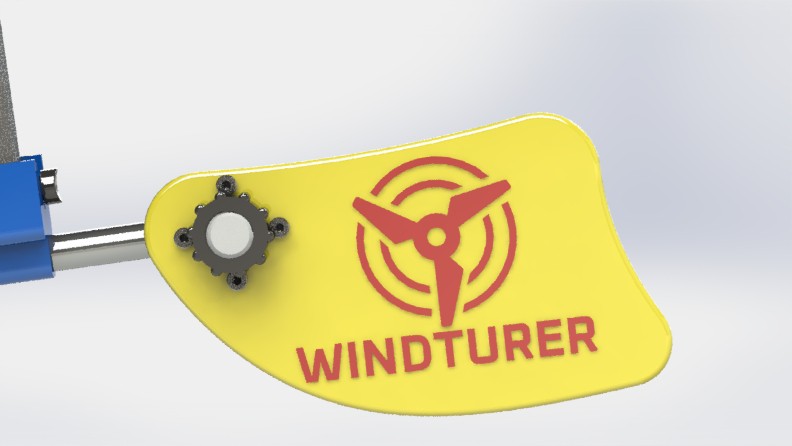
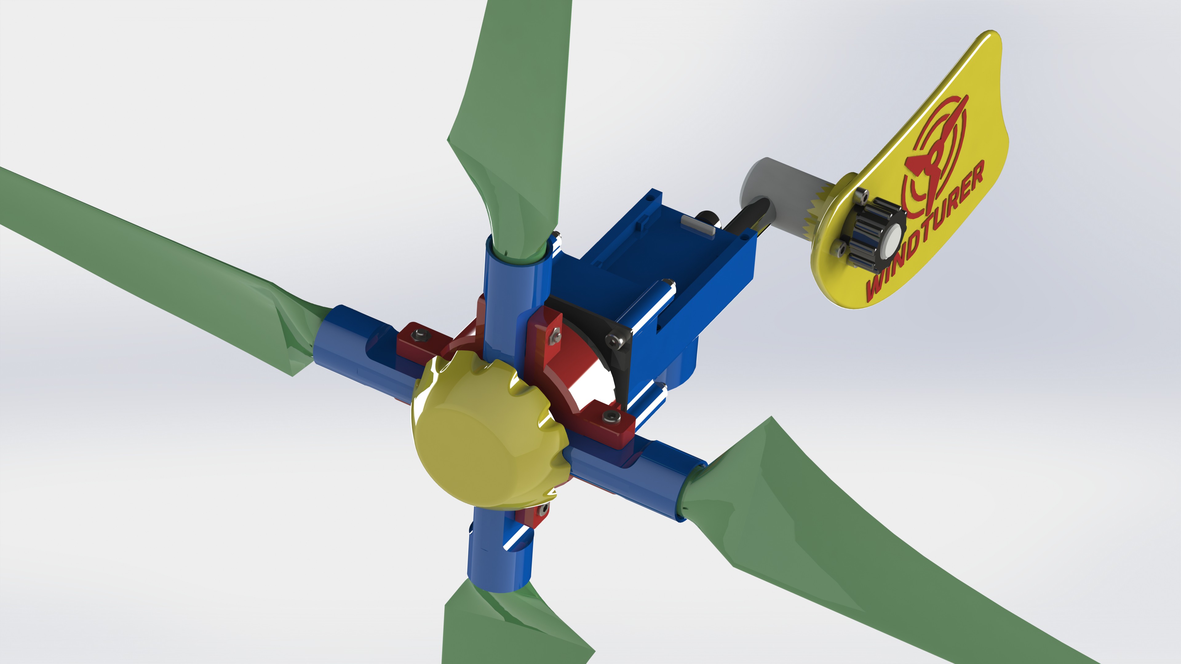
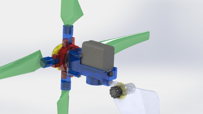
Hello everyone and welcome to the WINTURER project page, the Wind Turbine for your Adventures.

A few months have passed since I presented my first Portable Wind Turbine prototype on this platform. Its creation was inspired to provide a backup solution to recharge my electronic devices, during my explorations away from conventional power sources. Normally on my trips I take with me a 10000mAh (37Wh) PowerBank and a small 10W portable Solar Panel. Generally, the Power Bank is more than enough for me and the Solar Panel is a backup in case I use up all the power from the Power Bank and need to recharge my devices.

It happened to me that during an expedition a little longer than expected, I tried to recharge my phone and Power Bank when it had run out and there was no sun light at all. There was wind, but I wasn't prepared to take advantage of it. Suddenly, my phone had turned off completely and with it all the advantages of having it on (GPS, maps, possibility of communication in case of emergencies if I approached an antenna, the camera to get an interesting photo, an LED, etc...).

No matter what size of Power Bank you decide to take with you, at some point it will run out if things go off the rails and the return to civilization stretches out in time.

Solar panels also have their drawbacks, they depend on the Sun as is evident and they need to be perpendicular to solar radiation to extract their full potential. Many people hang the panels on backpacks and the orientation towards the Sun is a bit random which hardly contributes to generating energy efficiently. What if in your adventure destination there are no guarantees of having access to energy sources to charge your devices? Another aspect is that generally during the day we are on the move or in some activities while fulfilling our objectives and not precisely recharging our devices. As soon as it starts to get dark, it's time to stop moving and it's a good time to recharge, but unfortunately the sun light is gone. If there is any usable wind, this project may be a solution. Prototype 1 was my first proposal to take advantage of the wind to recharge my devices.

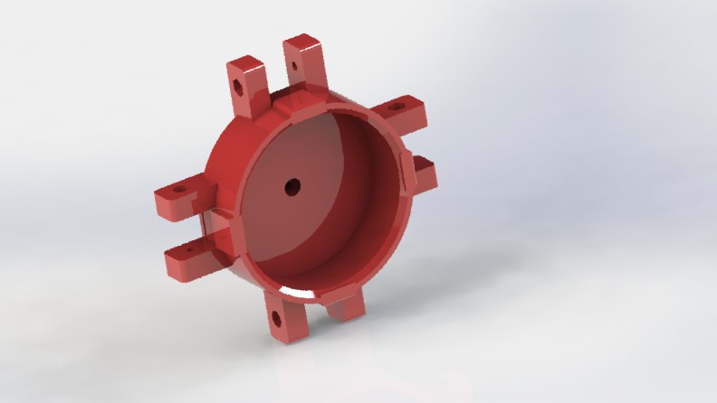
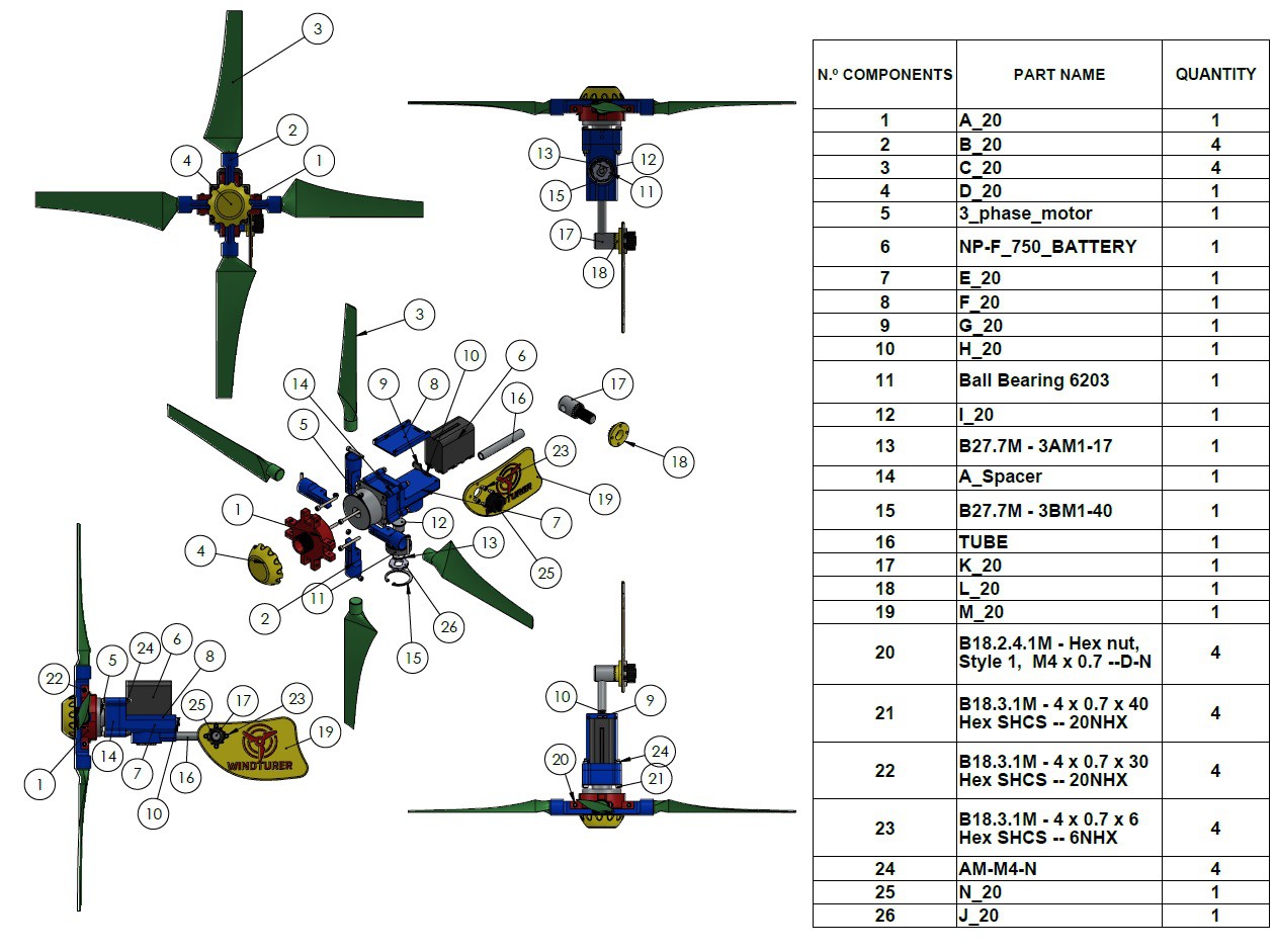
update note: I have been contacted by several Mechanical Engineering students and others interested in the original design files. I just uploaded them to GRABCAD at this link. I have spent a lot of time creating these parts. I hope they will be of great help to you!

I think there are many people in the World with similar needs. There are regions where access to conventional energy sources is very scarce and access to devices of this type could be a good alternative to keeping an LED lamp on at night or perhaps a small fan. There are also monitoring devices for meteorological variables, air quality, etc. that need energy sources for their operation where the sun is scarce. How about in disaster situations?

It is true that there is no wind everywhere and perhaps there is no other choice but to carry along 10Kg of Batteries and thereby have a certain “peace of mind”. But what if there is wind? Would you carry around a reasonably small, low-mass device that harnesses the kinetic energy of the wind to charge your most essential devices? If your answer is positive, then in this project you can find a solution.

What would be the drawbacks of a Portable Wind Turbine? Why apparently are there many people who are still  not convinced to take one on trips? Why aren't there several proposals for cheap DIY solutions, free to modify, replicate, share without being subject to patents and all the restrictions on development that this entails?
The answers to these questions were the compass and the obstacles that I have had to face in this project. I summarize what I think below about the most common comments.
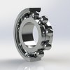
"A Wind Turbine that provides a "feasible" amount of energy needs to be relatively large and heavy. This is inconvenient if you have to carry it on your trips!" This is true, very...

Read more »

sheet - 12.93 kB - 06/25/2023 at 14:45

Download

x-zip-compressed - 13.70 MB - 03/15/2023 at 17:32

Download

Custom_NP-F_Battery.zip

Battery with a voltage range of 3V-4.2V, protected with a BMS.

x-zip-compressed - 104.81 kB - 12/13/2022 at 19:30

Download

I_20_NEW.STL

Wrong thread on part I_20. Error corrected!

Standard Tesselated Geometry - 582.80 kB - 11/15/2022 at 18:36

Download

RAR Archive - 15.18 MB - 10/06/2022 at 17:39

Download

View all 11 files

View all 11 components

  • New changes to Windturer_P4!

    adriancubas03/15/2023 at 15:30 2 comments

    Hi everyone,

    I have been making some changes and now I share with you the files of some variations that I have been making. You can download the pieces from the files section.
    I have developed a new articulation system for the tail. With the new parts, the tail can rotate 180 degrees and can be held in place by its own weight. It is not necessary to screw and unscrew continuously, only at the beginning to assemble the assembly. The tail is now a bit bigger too.

    I have developed a coupling piece to be able to use BLDC motors of the type used in camera stabilizers. To date I have not found any other alternative motors to use as generators that do not have to be modified to deliver the necessary voltage at low RPM (350-550) and that meet the size and weight

    requirements. These Gimbals motors are not the ultimate ideal solution since they have windings made with a very thin gauge of wire, which causes a somewhat high ohmic phase resistance (10-20 ohms).

    Any other more effective solution requires transformations to the motor windings which can be intimidating for some. If you find a generator solution that you think might work, let me know in a comment.

    In the following video I show you how, using the motor from the following link, you can easily turn on a fairly long 12V led strip by running the WINDTURER with an ordinary fan.

    I have my doubts about being able to do these tests with wind in an open environment without a regulator. The leds could burn out! Note that when the Windturer is running at no load the RPMs are much higher until it stalls. Always try to put a load on the WINDTURER that allows it to start easily but the RPM does not get out of control.
    In particular I used a Gimbal motor like this: https://aerialpixels.com/shop/motors/brushless-gimbal-motors/iflight-rc-ipower-brushless-gimbal-motors/ipower-gbm5208-180t-brushless-gimbal- motor-dslr/
    Parts for the new assembly are designed based on the dimensions of this electric motor.
    Any motor with similar characteristics will work correctly. Unfortunately I have noticed that they are becoming scarcer since fewer and fewer get to make their own GIMBALS.
    I'm currently testing one of the RCTimer brand on a garden non-articulated WINDTURER variant (https://rctimer.com/gbm8108-gimbal-brushless-motor-90t-for-red-epic-ect-p0459.html) and the results are somewhat better. Unfortunately they seem a bit expensive. In the future I will develop my own version of a 3D printed generator.
    See you in a next LOG, good luck to all!

  • New customized "NP-F" Battery solution with a voltage range of 3V-4.2V, protected with a BMS

    adriancubas12/13/2022 at 19:34 0 comments

    Hi everyone,

    One of the main problems that you may face when using this Wind Turbine is that it cannot overcome the impedance of the Battery to charge it. If in your area the winds do not blow so fast, if you have used the generator as it comes standard without rewinding it and in turn you have not used a Schottky diode rectifier, it is likely that the voltage obtained is low.

    To recharge a 7.4V nominal voltage battery (NP-F standard), it is necessary to apply a voltage higher than this at its terminals.

    I came up with an idea that could help many of you. What happens if we use a battery that requires a lower voltage to recharge?

    Here's my 3.7V nominal voltage version of a battery that looks like a standard NP-F. Also, this battery is 100% compatible with WINTURER-P4. So, if you already created your version of this Wind Turbine, you don't need to change anything.

    Another aspect to highlight is that it can be created from 18650 cells recovered from disused laptop batteries, power tools, etc... With this we are recycling and giving a new use to these batteries that would otherwise end up in the trash.

    Affiliate links appear in the following list

    For this battery you may need the following items:

    • 18650 lithium batteries ( https://amzn.to/3iUcL1b )

    • BMS 3V-4.2V ( https://amzn.to/3FojfNC )

    • DC power supply socket female panel mount connector ( https://amzn.to/3USBJLJ )

    • Contact pins ( https://amzn.to/3HxX1Lt )

    • Power bank PCB module board ( https://amzn.to/3PpWNbp )

    • 2.1 mm male barrel connector ( https://amzn.to/3WboOWi )

    ASSEMBLY INSTRUCTIONS:

    Download the STL and print them in ASA or PETG filament. The files were attached in the FILES section of this Project.

    In my case I did not use supports to print the pieces and I set the layer height to 0.2mm. Follow the filament manufacturer's recommendations for a successful print.

    Solder 2 different colored lengths of wire to two 2mm female connectors

    Drill two inside holes so you can get the wires inside the battery case.

    Apply some epoxy glue and insert the female pins (you may have to shorten them to fit into their positions)

    Solder the above wires to the P- and P+ pads of the BMS. Be careful! The polarity of the connections must match that obtained on the generator.

    Check with a voltmeter that all the batteries have a similar voltage. If there is one with a very different voltage you should not use it.

    Join the 4 Batteries and tin each other their positive and negative parts. Watch out! You should not join the positive and negative poles of the batteries together because you will cause a dangerous short circuit.

    Solder the Positive part of the Batteries to the BMS on the Pad marked with B+ and the Negative part to B-

    The Pads P- and P+ are also soldered to the DC connector respecting the polarity (the central part of the connector is positive and the outer part is negative).

    Solder the 2.1mm pigtail to the + and - connections of the Power Bank PCB Module Board. Observe the required polarity. This module does not have reverse polarity protection and will be damaged if this occurs.

    Place the Power Bank module in its case and cover it with 4 x 2.5mm screws.

    HOW TO USE THIS BATTERY

    Put the battery in the WINDTURER-P4 and capture energy from the wind. There is no danger of damaging the 18650 cells by overvoltage etc., since the BMS will manage the cells so that this does not happen.

    When you need to use the energy captured in the battery, remove the Battery from the WINDTURER and connect the BMS module. Press the side button twice until the side LED turns on, then press once to turn it off.

    The lcd panel will display an estimate of the battery charge. Connect any USB device to its ports to provide them with the power they need.

    These Power Bank modules can handle currents of even slightly higher 2A.

    Note: Never leave the PowerBank module connected to the battery...

    Read more »

  • WINDTURER power estimation with TRACKER software

    adriancubas10/15/2022 at 17:10 0 comments

    I have been thinking of a simple methodology to correlate the data obtained from the generator, with the behavior of Windturer in normal operating conditions. I have had some accuracy difficulties with certain manual tachometers. I'm still looking for a quality one.

    My first idea was to try to place optical sensors and multimeters on the Windturer while it was operating, but placing all that equipment can be cumbersome and time-consuming. Also recording the data can be challenging with the conditions and equipment that I have. Recreating a variable wind, similar to that of Windturer operation under normal conditions, is also another challenge.
    The results that I show you below have limitations, but it can be a method of estimating performance.
    With the battery installed and under the influence of the wind generated by a fan created with a BLDC drone motor, I was able to generate a wind of around 10.5km/h as seen in the anemometer placed in front of the Windturer.
    By shooting with a slow video camera capable of 240 frames per second and using TRACKER software, a free video analysis and modeling tool built on the Open Source Physics (OSP) Java framework, I was able to make certain measurements, in particular the linear speed of the tip of the Blade for a short period of time.
    Averaging the values in m/s and converting them to RPM, I was able to conclude that with a value of 10.5 km/h of wind, the rotor rotated at approximately 670 RPM. Correlating this value to those obtained in the generator measurements, it can be inferred that the battery charging current at that time was 0.3A or 300mA. At first glance it might seem like a low value, but keep in mind that 10 km/h of wind is not a high value, and in this case it is very turbulent.
    There are complete guides to learn how to use this software and I think it may be appropriate for your measurements. See you!


  • How can you start using Windturer?

    adriancubas10/10/2022 at 17:47 0 comments

    Hi everyone

    In the next video I will show you how you can easily install Windturer and collect free energy. As you can see in the video, the installation was carried out at a low height with respect to the ground and the wind speed was not high. Despite this, Windturer was able to initiate his move!

  • Windturer-P4 design is ready!

    adriancubas10/04/2022 at 18:34 0 comments

    I am happy to say that you are now ready to download all the Windturer-P4 files. With these files you can print all the pieces. You also have the possibility to modify what you want in your favorite CAD program, depending on your goals and needs. The files can be downloaded directly from the Files section of this project.

    Additionally our Portable Wind Turbine already has a logo, brand and slogan. They are shown in the following image. I would love to hear your comments about it.

    "Windturer: The Wind Turbine for your adventures"

    Although the essence of this new P4-Prototype is consistent with the design philosophy of the P1-Prototype some improvements have occurred.

    I believe the feedback I received on this article by Robin Kearey on Hackaday.com: https://hackaday.com/2022/05/02/hackaday-prize-2022-a-3d-printed-portable-wind-turbine-for -hikers/ were decisive in the improvements that I have been implementing. Thank you all for your criticism and suggestions.

    All the pieces of the new design have been printed on ASA Filament for validation. The parts have tried to be designed in such a way that they are easy to print even with the recommended type of filament material. In particular I have used this one from the Polymaker brand https://amzn.to/3V0mu4I *affiliate link*

    Kyle Burns from https://essentium.com/ has collaborated with this project and recommends printing with this type of filament with exceptional characteristics : https://essentium.com/product/essentium-pps-cf/

    In this design, a generator based on a Stepper Motor is no longer used, but rather a BLDC motor, three-phase permanent magnets, rewound so that it complies with a 60 KV ratio. I have dedicated a Log where you can find additional information:

    https://hackaday.io/project/185070-3d-printed-portable-wind-turbine/log/211246-results-of-the-electrical-measurements-to-the-generator-p4

    Blades have been redesigned and optimized with QBlade software. Its characteristics and simulation results can be found here:

    https://hackaday.io/project/185070-3d-printed-portable-wind-turbine/log/211683-introducing-prototype-4-blade

    They turn out to be more efficient Blades, with less mass and greater mechanical resistance. A 4 Blade configuration is now used which contributes to a higher Torque for rotation at low RPM and allows them to fold much better over the central body.

    The central hub is glued directly to the external rotor of the BLDC motor without the need for Collet Prop Adapters. In the first prototype this was a recurring problem for those who replicated it, since the coupling to the shaft was not entirely secure and under certain loads there were

    slips. This makes it possible to shorten the length of the arms of the Central Hub and contributes to a greater mechanical resistance of the assembly.

    In this prototype, an external electrical cable is no longer used to conduct electricity. It was decided to place on his body batteries of the NP-F type. These batteries are interchangeable. You can leave one recharging and then place another etc. It behaves similarly to a standard NP-F battery charger. You can also use the batteries that best suit your requirements, with or without USB output, of greater or lesser capacity. Also with this you can decrease the total weight of this Portable Wind Turbine if you really don't need such big batteries. By being able to easily remove the battery and replace it, we avoid its obsolescence if the battery is damaged.

    The ecosystem of NP-F Batteries is quite large. They are often used in equipment and lights for filming. There are manufacturers that have developed mounting plates with multiple outputs of different voltages, including PD and USB A for this type of battery. I have tried this particular one and find it very useful https://amzn.to/3ExhChR *affiliate link*

    The central body includes a cavity where the rectification circuit is placed as...

    Read more »

  • NP- F batteries as energy storage system of the Windturer-P4

    adriancubas10/03/2022 at 18:00 0 comments

    From the beginning of this Project I always wanted to store the energy captured in lithium batteries, preferably in 18650 type cells. I consider that these cells are a proven technology, with a high energy density, with a high level of safety, accessible and with a not so high price.

    NP-F batteries in their different configurations (330,550,750,970 etc…) have this type of cells inside in a 2S configuration, that is, two cells connected in series. In a previous Log, where the electrical characteristics of the generator were addressed, it was concluded that a 2S configuration with a voltage range of 6V-8.4V is recommended as a storage system and this type of battery has this configuration.

    As a reference let's take the Samsung INR18650-25C, its technical data sheet can be consulted here: https://www.powerstream.com/p/INR18650-25R-datasheet.pdf

    This type of cells can support a maximum of 4A of recharging current for each cell, this is a higher value than that delivered by the generator of our Portable Wind Turbine. We can extract from them a maximum of 20A of discharge current continuously. They have a capacity of 2450mAh, when discharged at a rate of 10A. After 250 charge and discharge cycles they offer only a 2Wh decrease in capacity from the initial 7.4Wh (4A charge current up to 4.2V and 20A discharge current down to 2.5V). At -20 degrees Celsius and  a cycle of 10 A of discharge current and 4 A recharge current, they retain 96 percent of their original capacity.

    I don't think that all NP-F battery manufacturers use this type of Samsung cells, although I think that the characteristics of the ones they use should be similar in several respects.

    Also, NP-F batteries have a BMS circuit inside them that adds safety and protection functions to the cells. I took the job to disassemble one of these to see its internal structure and analyze its characteristics. Specifically, it was an NP-F970 with a charging circuit and USB output https://amzn.to/3SsQVih *affiliate link*

    In the previous photo you can see that this battery is made up of (6)) 18650 cells in 2S3P configuration. The circuit that can be seen above these cells is a BMS (Battery Management System) and the one that can be seen below is the charging circuit, charge level indicator and USB output. You can charge this type of battery with a charger specialized in NP-F batteries or simply through a micro USB connector. You can also power your compatible USB devices directly from this battery.

    These batteries also come encapsulated in a plastic case that, while I don't necessarily consider it waterproof, I do consider dust and splash resistant. If any of you know if there is any IP-X certification for this type of battery, could you tell me where to find it?

    One of the main functions of the BMS is to prevent overcharging and overdischarging. In addition, these circuits protect against short circuits, limit the maximum charge and discharge current. To test these features, I ran several experiments trying to find answers to the following questions:

    - Does this battery have short circuit protection?

    - What is the maximum charging current supported?

    - What is the maximum load current supported?

    - What is the maximum voltage that the BMS allows to the cells?

    - What is the minimum voltage that the BMS allows to the cells?

    The battery has short circuit protection.

    The maximum charging current supported in my experiments was around 4.75A as can be seen in the video. For this, a variable current source was used and the current value was increased until the BMS circuit interrupted the charging process. The experiment was repeated several times and the results were consistent.

    To check the maximum discharge current a Load Tester was used like this https://amzn.to/3yd4HNM *affiliate link*

    This battery exceeds the 5A discharge current of this module, triggering its overcurrent protections. I tried to use a 55W car...

    Read more »

  • Introducing Prototype 4 Blade

    adriancubas10/03/2022 at 02:11 0 comments

    Having designed and printed several Blades from the previous Prototypes and experimented with them, I still wasn't happy with the results and knew that they could be more compact and efficient.

    For example, the Blades of Prototype 1, which I call the "Intuitive Blades" were designed without the assistance of specialized programs such as QBlade and although their behavior was correct, their performance is much lower than the one I present here. Also, this Blade has a mechanical weakness and under reasonable stress they would always break in the same place. Below is a photo of this problem.

    In the case of the Blades of Prototypes 3 and 4, they turned out to be very large for the objectives of this project and it is not very clear to me that they can withstand winds of about 35Km/h.

    So that the Blades P2-P3 could be printed on an Ender 3-type printer, not exceeding the height of a 2-liter soda bottle, a kind of hinge was designed that joined the two parts of the Blade. This area is also prone to damage, especially since it is a larger Blade and the "centrifugal" forces during rotation are greater.

    I do not rule out using this type of Blade in other projects if I use other types of more resistant 3D filaments, but I think that for the requirements of this Project they are a bit oversized and make manufacturing more complex and make the project more expensive.

    The Prototype 4 Blades turned out to be the right balance I needed. They do not exceed 22cm in length and their performance is on wheels.

    Let's analyze some images of the QBlade program where I designed them.


    The Blade P4 is based on the NACCA 6409 airfoil.

    One of the frequent problems in this type of fixed pitch wind turbines is starting at low RPM. In order for the Blades to do their job efficiently they must operate at relatively high rotational speeds. This type of profile has proven to be effective at low RPM and guarantees higher lift forces during starting. It is also a narrow profile that results in thinner Blades and lower mass which contributes to less material being spent when printing them and lower forces being generated during rotation.

    In the image above it can be seen that this profile reaches its maximum Lift coefficient (Cl) around 12 degrees of pitch, however we are interested in the angle for which the relationship between the lift and drag coefficients is maximum. The angle for which this occurs is around 5 degrees. When assembling the propellers with the rest of the set, the Blades must be rotated around this angle. All the simulations were made considering a Turbulent Flow (Reynolds Number 100000). This is due to the typical operating conditions of this wind turbine at very low height from the ground.

    In the image you can see the position, chord length, angle of attack and type of profile data obtained after the Betz optimization for a Tip to Speed Ratio of 3. Knowing these values and the type of profile chosen, the Blades can be modeled in the 3D design programs. The Blade was sectioned into 11 parallel planes with a separation distance of 22mm between each. In the Files section, the analysis and design file of the Prototype 4 Blade is included.

    QBlade is a public source, cross-platform simulation software for wind turbine Blade design and aerodynamic simulation. https://qblade.org/ 

    This simulation tells us that at wind speeds of 30km/h a maximum generation power of approximately 40W is obtained. At lower speeds and more common at low altitude, say 20 km/h we get about 12W. Although it could be stated that we have designed a 40W Power wind turbine, this statement is really not very transparent and only in exceptional cases could we obtain those values.

    In this LLT (Lifting-line theory) simulation, the three-dimensional behavior of the designed Rotor is appreciated when it faces a wind flow of 6m/s (21.6 km/h), obtaining about 26.3W of power. In real conditions and considering...

    Read more »

  • RESULTS OF THE ELECTRICAL MEASUREMENTS TO THE GENERATOR P4

    adriancubas09/23/2022 at 13:40 0 comments

    Following a procedure similar to the electrical measurements that I have made to the previous generators (motors), I present below the results that I obtained with the Prototype 4 generator.

    I coupled the P4 generator to a three-phase electric motor whose RPM was varied with a VFD (Variable Frequency Drive). Using an oscilloscope with a magnetic probe, I accurately detected the rotational frequency and thus the RPM at which the P4 generator was rotating. Measurements of the relationship between open circuit voltage vs. RPM, short-circuit current vs. RPM, as well as charging current for 18650-type lithium batteries in 1S2P and 2S3P configuration, respectively, vs. RPM were made.

    A DC Boost-Buck Converter type converter inserted between the generator and the batteries was also used to see if there was an increase in the charging current.

    During the experiments and measurements carried out, the following questions were answered

    1- What is the electrical resistance value of the motor windings?

    2- At how many RPM of generator P4 is 1V (kV value) obtained?

    3- What is the maximum short circuit current at the expected RPM in the rotor?

    4- What is the best configuration of 18650 batteries (1S or 2S) for the storage of the energy generated in the wind turbine?

    5- Does the use of DC-DC converters favor an increase in the charging current of the batteries with this generator and under the expected operating conditions?

    The results presented below will influence the design of the Blades and the energy storage system.

    The motor windings turned out to be approximately 6.5 Ohms. Recall that this generator was wound with 80 turns per pole in a star-shaped three-phase configuration. The wire gauge used was 0.35mm in diameter. In total there were 12 poles.

    The motor turned out to be approximately 60kV, that is, for every 60 turns of the rotor, 1V is obtained. This graph shows the values obtained.

    The maximum short circuit current was 1.7 (A) at 888 RPM. The results are shown below.

    The charging current values in the single cell configuration are higher than those of 2 cells, however, the energy generated in both cases is very similar at the same RPM. I consider using the configuration of 2 18650 cells in series, since the resistance torque is less in the generator. It also makes it possible to obtain the necessary RPM for the rotor to work with good efficiency, at higher RPM. In addition, the resistance torque is less when the rotor begins to rotate.

    The cells that were used are capable of storing 8.14Wh of Electric Energy each. In the case of the 2S3P battery, it has a total of 6 cells, which means that it is a 48.86Wh battery. If we divide this value by 7.4V, which is the nominal voltage value of two 18650 cells in series, we obtain that it is a 6600mAh battery. This Batt at a stable charge rate of 0.6 A would take around 11 hours (estimate) to fully charge. A Samsung Galaxy S22+ battery is 4500mAh, but at 3.7V, which translates to about 16.65Wh. Ignoring the energy losses, we can estimate that in 11 hours, you would be able to charge this phone at least approximately 3 times. About 3 hours and a half approximately for each charge of the phone.

    There are several assumptions in this reasoning, but I think it gives an idea. Results may vary and charging current may be higher or lower on average, depending on wind speed.

    A DC-DC (Boost-Buck) converter was also used in the experiments. At approximately 300 RPM in the generator, which corresponds to about 5V of voltage obtained, the converter begins to deliver an output at stable voltage. Through two potentiometers this value can be configured up to 35V. It is also possible to set the maximum delivery current of this module up to a maximum of 4A.

    However, when the batteries to be charged are connected in both configurations (1S and 2S), it is not capable of regulating the output voltage. The voltage drops to similar...

    Read more »

  • PROTOTYPE 3 REJECTED!

    adriancubas09/17/2022 at 15:24 0 comments

    It's hard to say, but I had to abandon the development of prototype 3. Don't worry, I'm not going to abandon this project, in fact, today I am in a much more advanced step than what I am going to describe in this Log.

     The main reasons that supported the design of prototype 3 were precisely related to the characteristics of the selected generator. Let us remember that it was a BLDC motor, recovered from a DJI M600 Drone. This type of motor, as explained in the measurements made to it in a previous Log, is capable of producing one volt for approximately every 130 RPM. To get 10V the propellers had to turn at 1300 RPM, very fast for normal wind conditions. In order to obtain those RPM in the generator (electric motor) but for the propellers to turn at lower RPM and taking advantage of the torque of the new designed propellers, prototype 3 includes belts and pulleys. Here the problems begin, this design requires at least three bearings, two GT2-type pulleys and two custom-designed axles, in addition to the remaining bits and pieces from previous prototypes. It also turned out to be very large and heavy. The structures that would support it would also have to be larger and that would also lead to more weight. Too complicated and expensive for my taste! I inadvertently fell into the trap of looking for complicated redesign paths.

    I know many people hate Stepper Motors as generators and to a certain extent I understand them (they are inefficient and quite heavy), but believe me that in wind generation devices as small as this project, it is very difficult to beat at low RPM. That is why my first build (Prototype 1) used a Stepper Motor.

    Prototype 1 turned out to be well accepted and today I am proud to receive feedback from users of this platform who have already replicated it and are getting their own performance and application experiences. It has been used as a power source for automatic chicken coop doors, even as an electrical power source for remote sensors that measure humidity, temperature, wind speed, etc.

    Prototype 1 proved to be feasible, but there is certainly room for improvement and I have been on that path for a few months now.

    Prototype 4 has already been designed and features a modified BLDC motor as a generator. The same motor I once rewound from 35 turns per pole to 50 turns today is 80 turns per pole (12 Poles in total) using a thinner wire gauge (0.35mm diameter) and improving my winding skills lol. It was connected in a star configuration with three phases. In the next log I will explain its electrical performance, but let me tell you that due to the previous tests that I have been able to carry out, it perfectly meets expectations and exceeds the stepper motor of Prototype 1 in generation.

    I leave you some photos of the process and a small demonstration. Thanks for reading. You guys are all amazing. See you in the next Log!!!

  • Rectifier Circuit + Capacitor ready!

    adriancubas07/29/2022 at 15:50 0 comments

    In a previous Log I published the Full Wave Rectifier + Capacitor circuit that I intend to use in this Wind Turbine. Thanks to PCBWay and his kind team this circuit is now a reality! From what I have been able to verify, the manufacturing and quality control process is very well structured and at all times the user can know what stage of the process their order is at. They have a very intuitive and very helpful Web platform. Something that caught my attention is that they sent me preliminary photos before the final assembly to check any detail that could be correct or not and correct it before concluding the work. After my confirmation they proceeded with the remaining steps.

    I have shared the project on the PCBWay digital platform at the following link. Through this you can order its manufacture and I guarantee that the results will be incredible.

View all 20 project logs

  • 1
    STEP 1: DOWNLOAD AND PRINT ALL STL PARTS OF THE ASSEMBLY

    In this video I show you a summary of how I executed the steps for the construction of the WINDTURER-P4 Prototype

    Instructions and Materials List for Prototype 1 can be found here
    https://www.instructables.com/HOW-TO-MAKE-a-PORTABLE-WIND-TURBINE/

    You can download the STLs from here in the FILES section. The most up-to-date files are published under the prefix WINDTURER-P4. These files include all improvements made since Prototype 1.

    I have also included the files (STEP_IGES_X_T_3MF) in case you want to take a closer look at the assembly or change something, depending on your interests and needs. If you need any special type of file format let me know and I'll see if I can help.

    I have printed my prototype on ASA filament, specifically from the manufacturer Polymaker https://amzn.to/3ryQKGe  affiliate link. It is recommended that the 3D Printer, print in a closed space without drafts and use a heated bed at least 90 degrees celsius with some glue or lacquer for printing. I printed my pieces at 250 degrees celsius. PETG will likely work as well, though I haven't tested it. PLA should be discarded because it has very low adhesion between layers and on very hot days the pieces can deform.

    I have included a zip file of my CURA-GCodes , in the files section for you to analyze how the pieces were printed. The layer thickness was 0.2 mm in all cases. I used a Longer LK4-PRO printer with a 0.4mm nozzle.

    The propellers were printed one at a time. It took about 6 hours each. I used supports and the position was as shown in the video. The infill pattern was TRIANGLE and I used the CURA software as Slicer.

    Additionally you may need some accessories to fix the tripod to the ground. I have printed some from thingiverse via these links
    Tent pegs: https://www.thingiverse.com/thing:2758339
    Tent cord fastener: https://www.thingiverse.com/thing:3676148

    How to use the tent cord fastener : (https://youtu.be/w34OC063BQA)

    Don't get lost with file names!

  • 2
    STEP 2: SMOOTH OUT SOME IMPERFECTIONS THAT RESULTED FROM THE 3D PRINTING PROCESS

    It is recommended to sand the pieces in the places where the supports were created. Also to smooth out any bumps that could affect performance or cause damage to hands when handling.

    Be careful with the sharp edges of the plastic, they can cut your skin.


  • 3
    STEP 3: SCREW THE ENDS OF THE BLADES TO THE CENTER HUB.

    All the holes in the designed parts are for M4 screws. Install the bolts and nuts as shown in the video, but do not over-tighten. The ends of the blades shall be free to articulate 90 degrees. Then install a locknut so there is no chance of them coming loose.

    note: Why was it necessary to make these blade terminals? Wasn't it easier to integrate the blades with these parts in one piece?
    For several reasons it was designed this way:
    -This makes it possible to change the angle of attack of the Blades for different scenarios and experiment for better performance.
    -It makes it possible to make optimization changes to the blades from QBlade and would also result in blades compatible with the rest of the assembly. In Qblade you cannot model the Blades, the software creates them but you cannot freely create shapes.
    -Also by doing it this way you can take advantage of the maximum height of common Ender 3 type printers.

View all 11 instructions

Enjoy this project?

Share

Discussions

Andre Powell wrote 12/31/2023 at 10:39 point

Hi Adrian,
This is BRILLIANT !
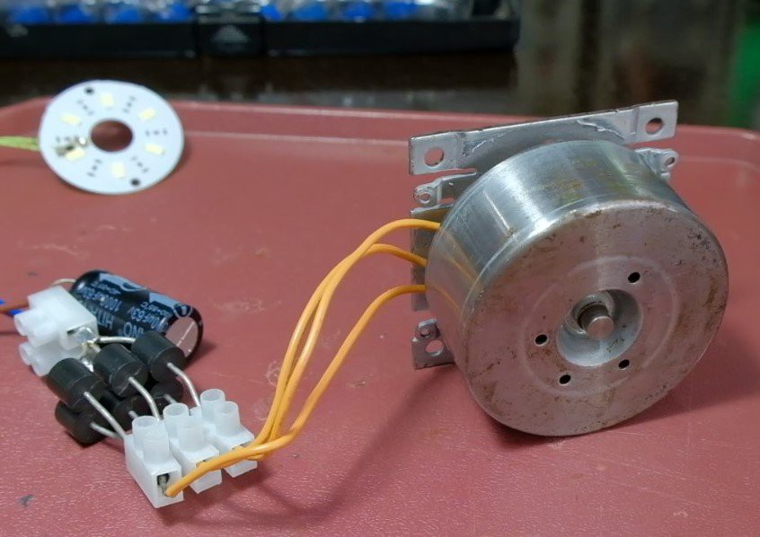
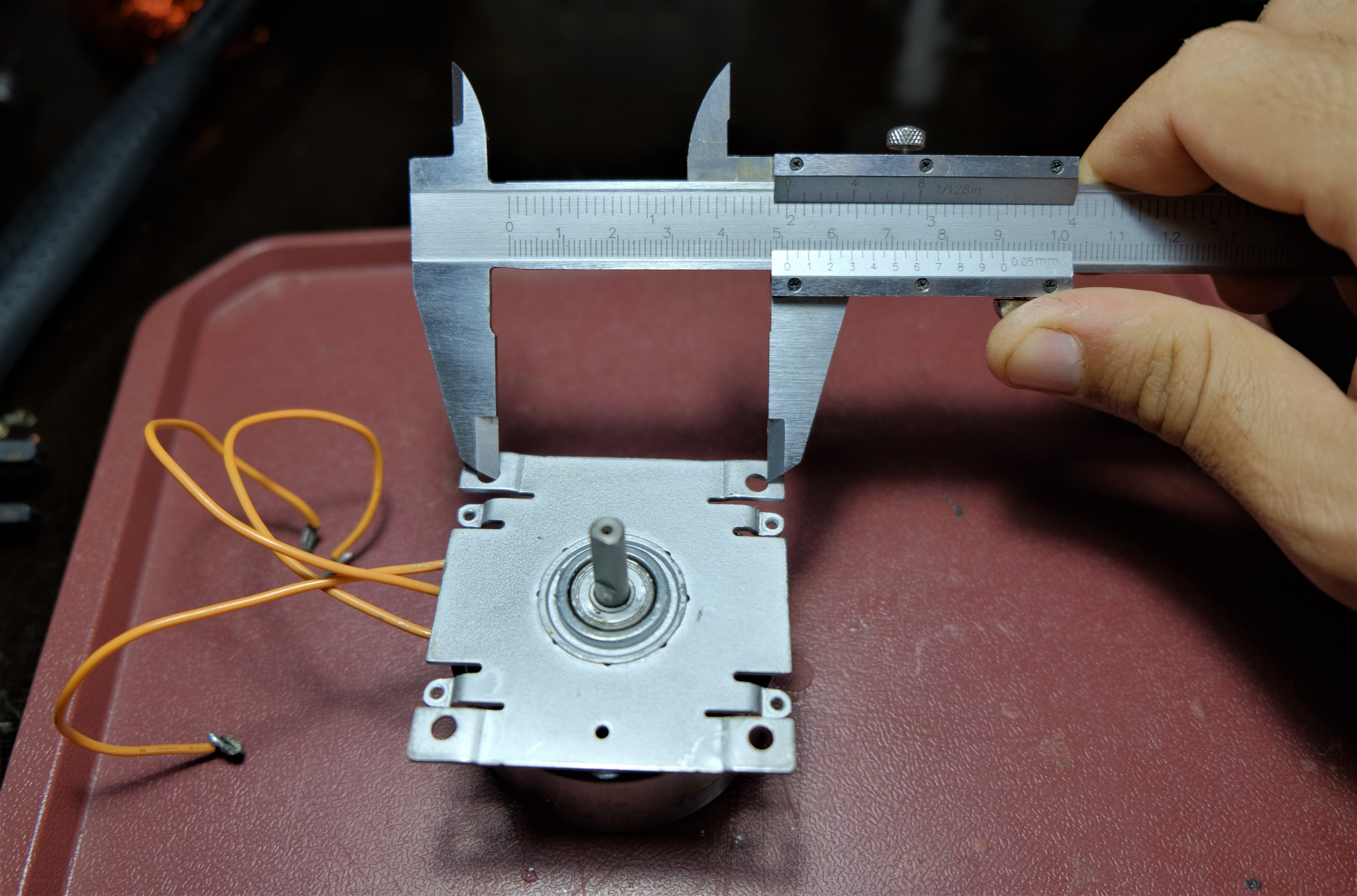
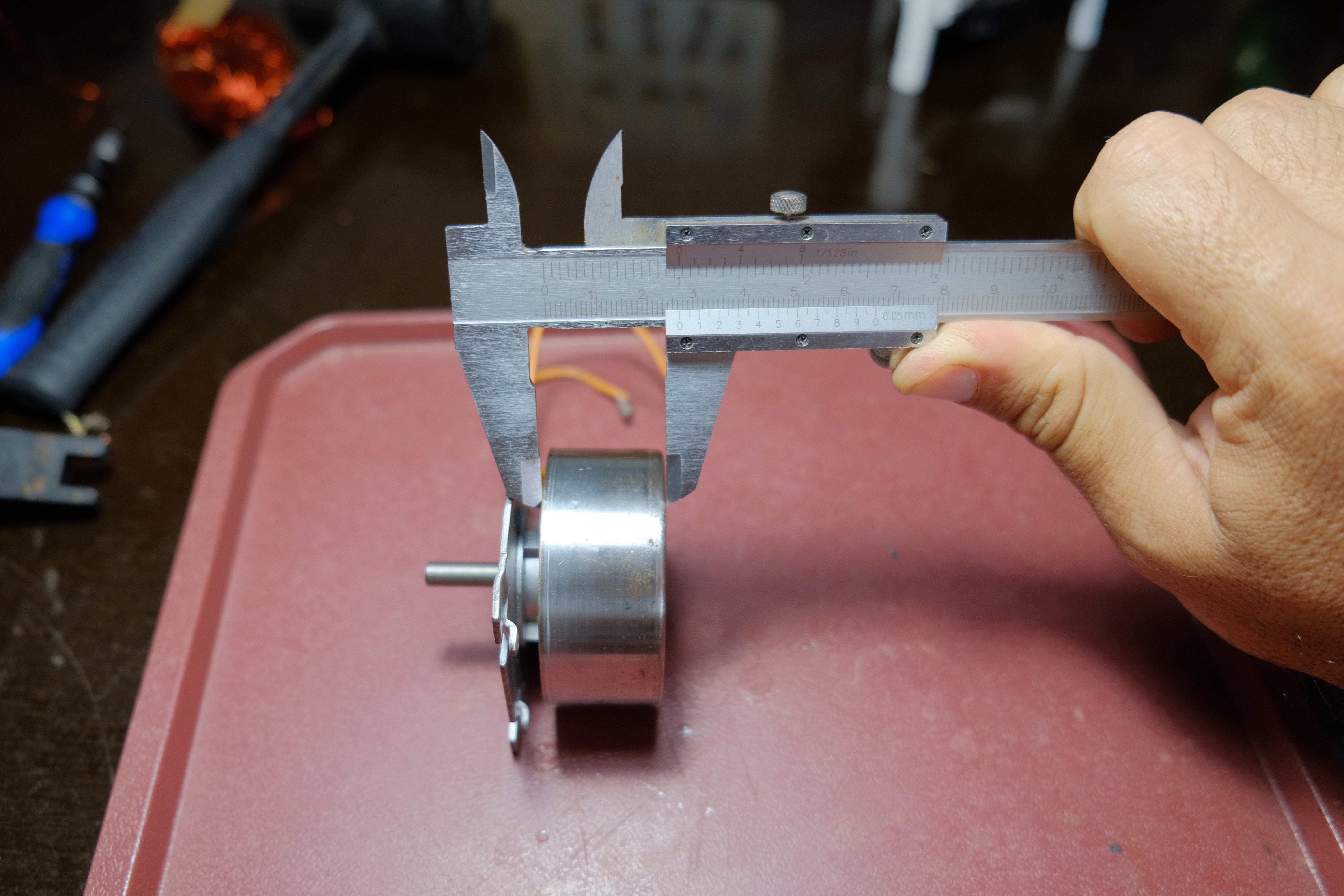
I downloaded the files and discovered that I could not obtain the specific motor here in the UK.

I did get a motor and proceeded to up the design stl files. Also I couldn't get hold of the battery pack you mentioned.

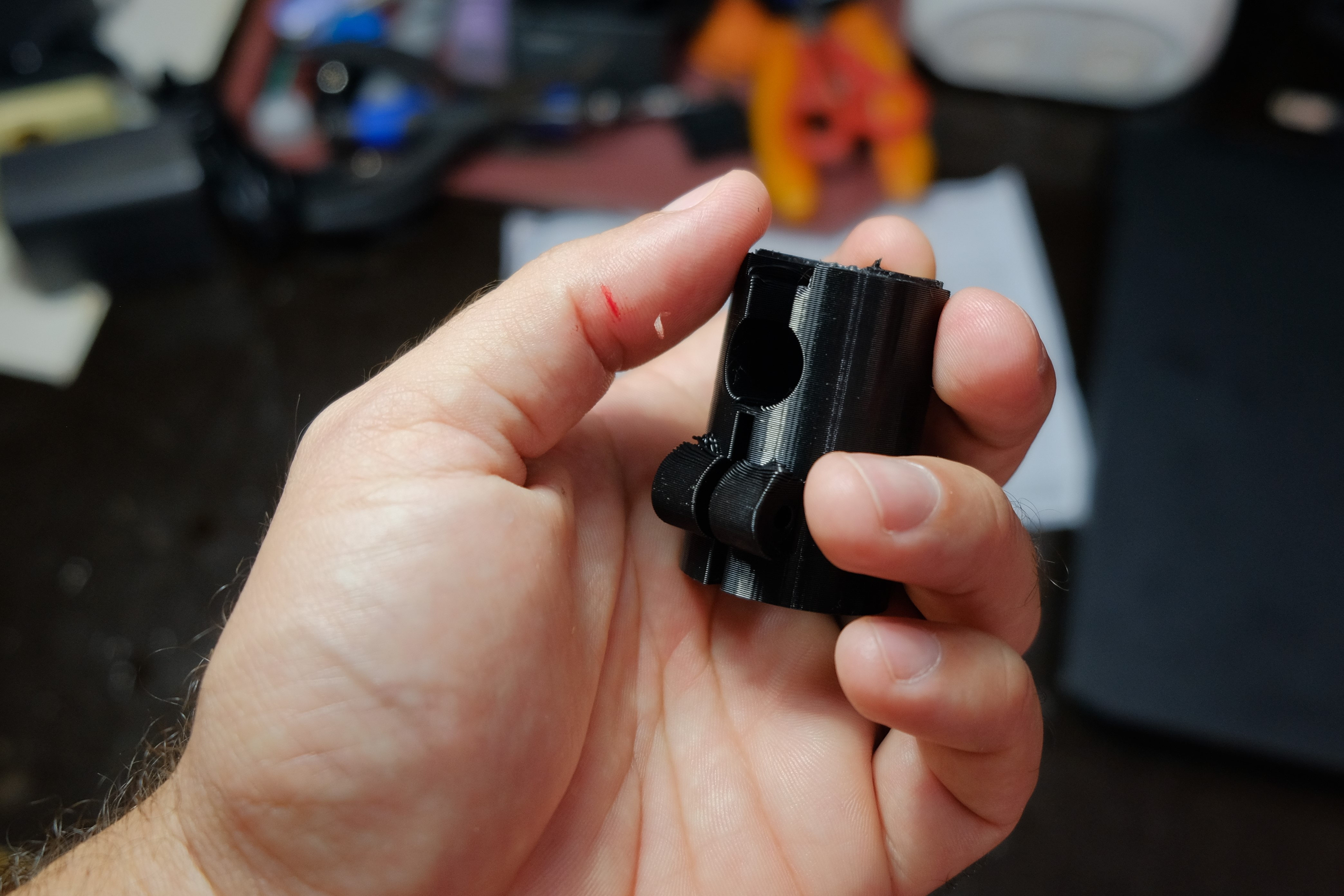
I decided what the heck, updated the design to fit it all together. What I also discovered was that the thread on my tripod is not metric. I did order some nuts and then created a captive nut block which then had a captive M6 bolt. The piece that sits inside the bearing has melt/push  M6 'nut' (can't remember the actual name) which then this can connect to.

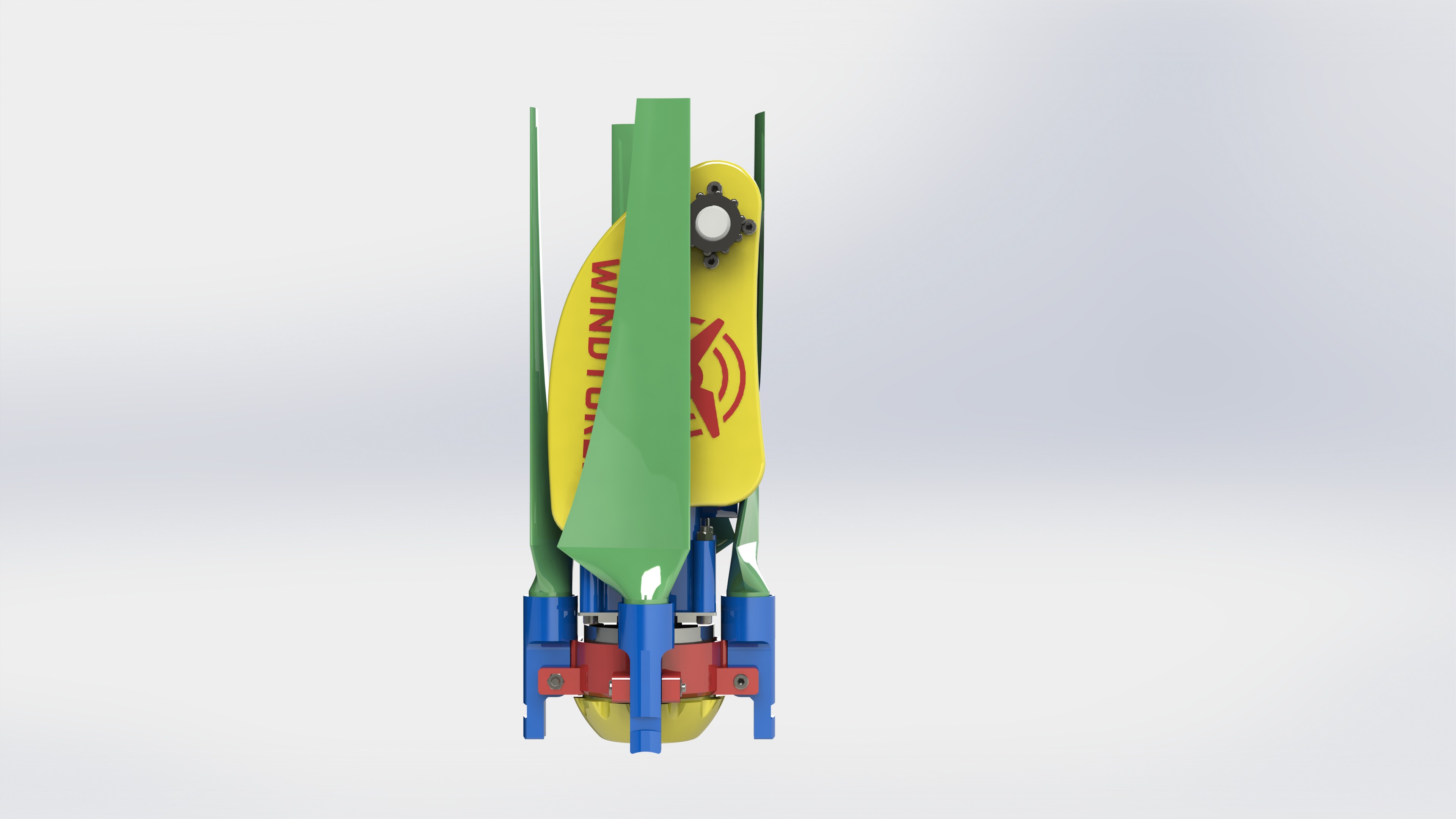
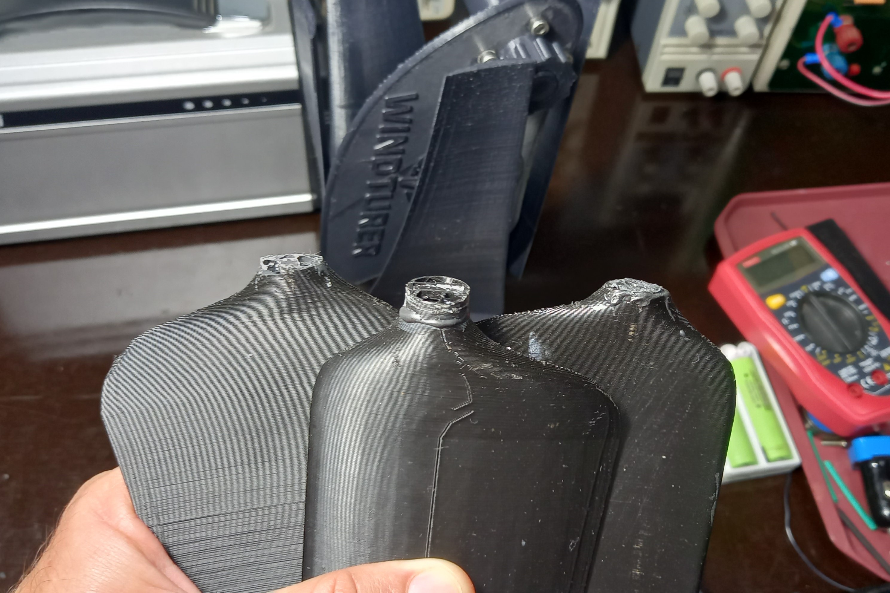
The Turbine blades must have a sturdy raft and it must have the supports also put it, I discovered this as after a few attempts to print the them. Note I am lucky in having a 3D printer that can print up to 25 cm I printed them standing up. Also they are honey combed at IIRC 25 % thus keeping them light and strong.

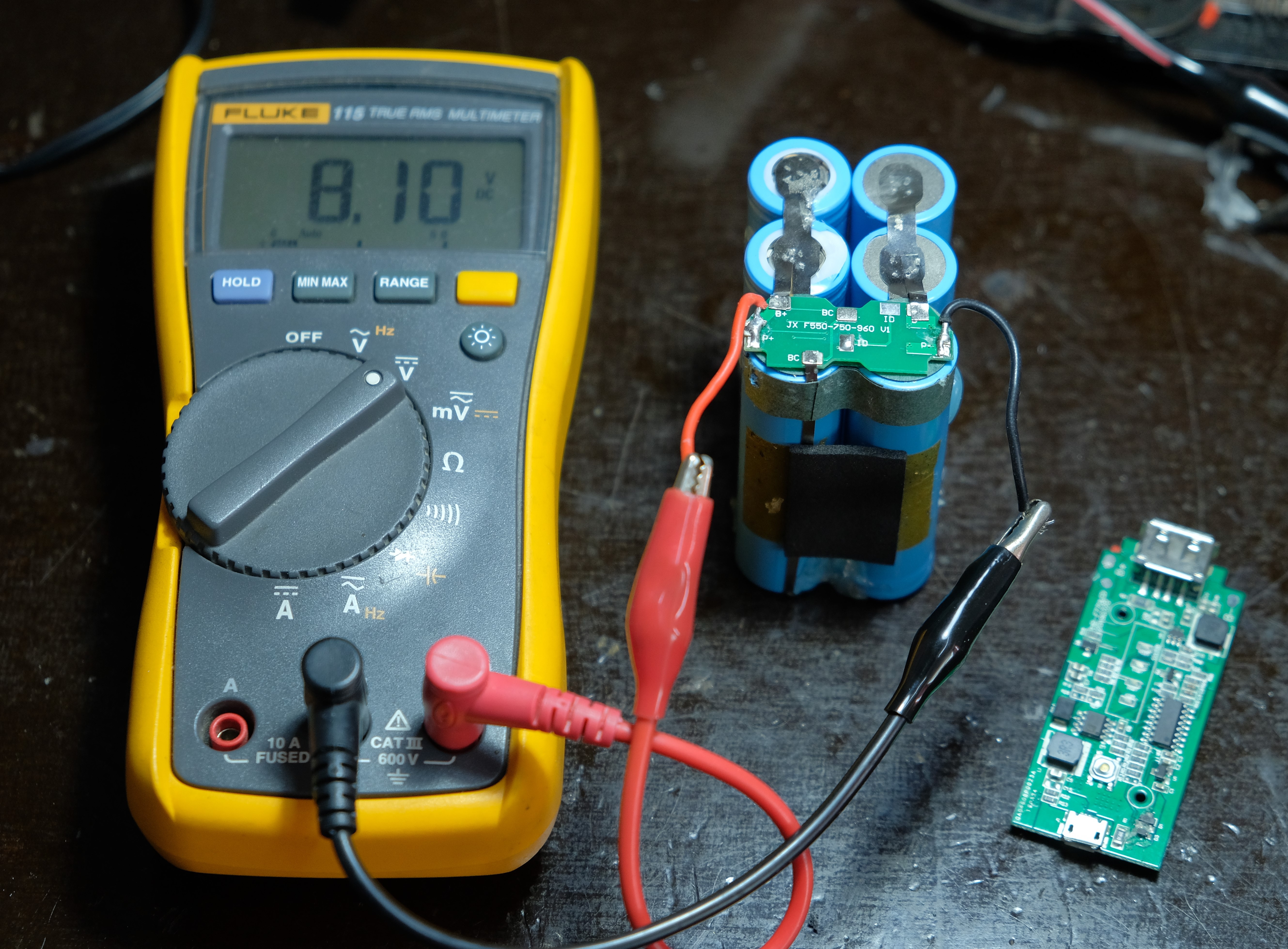
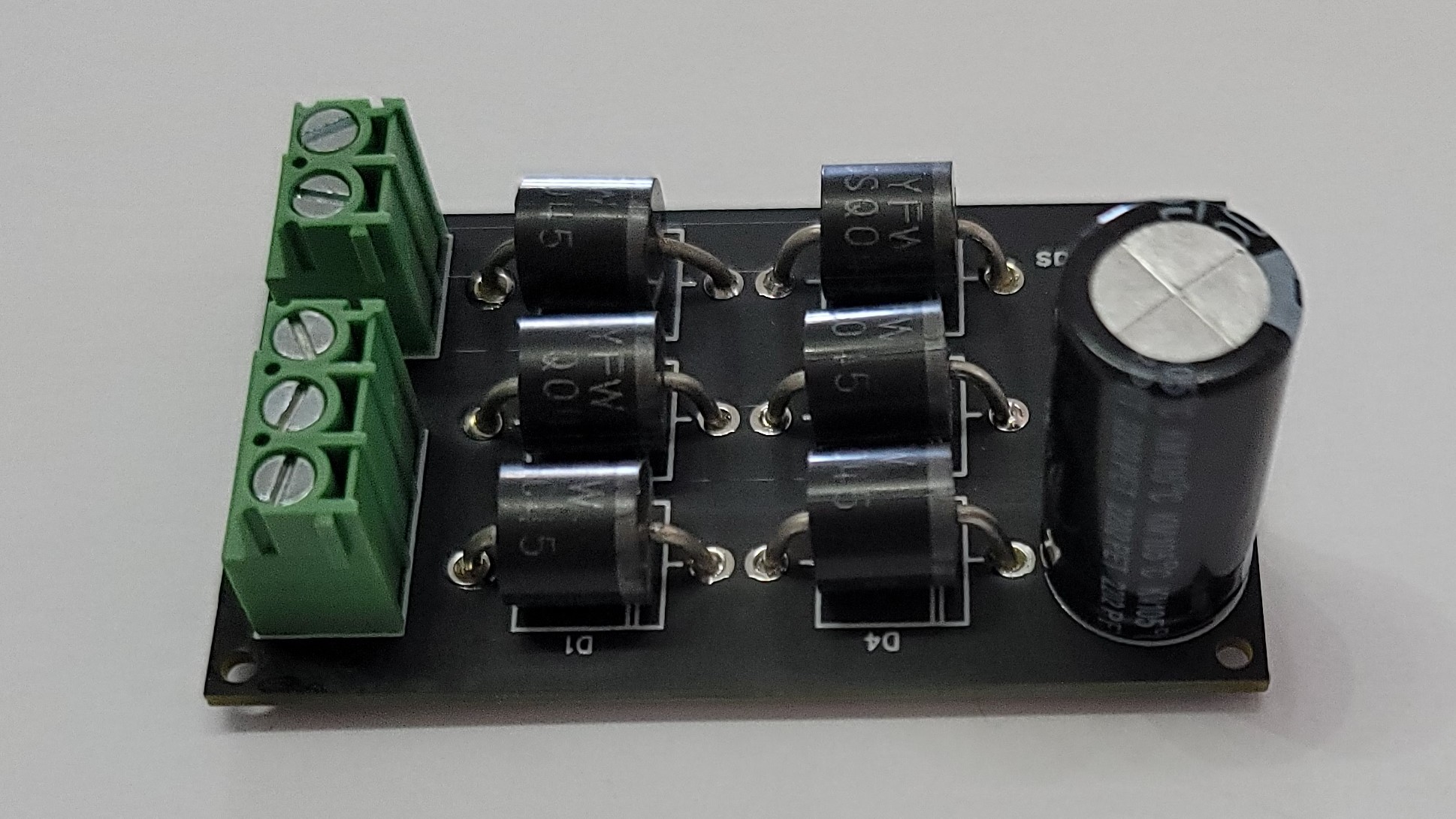
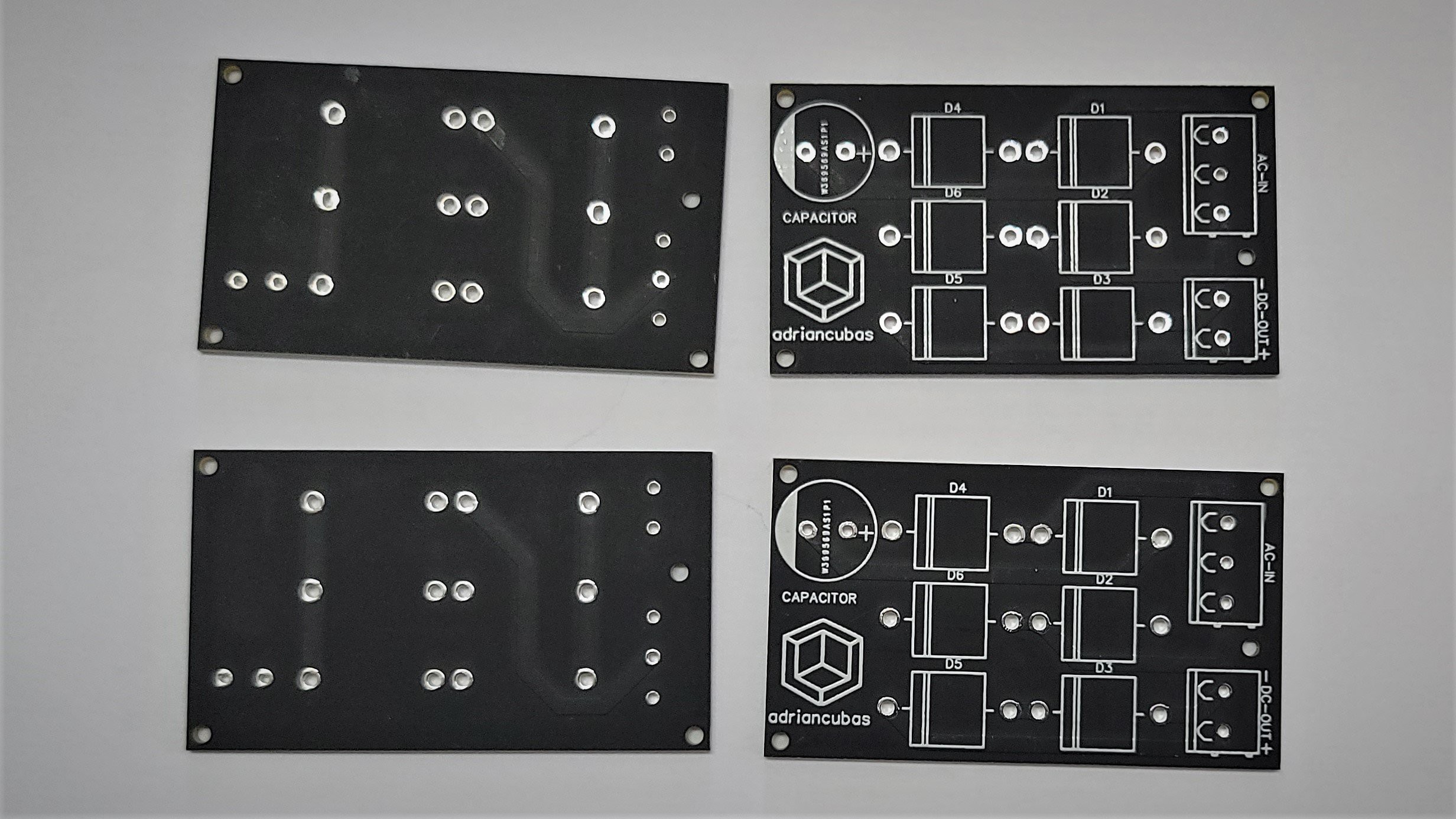
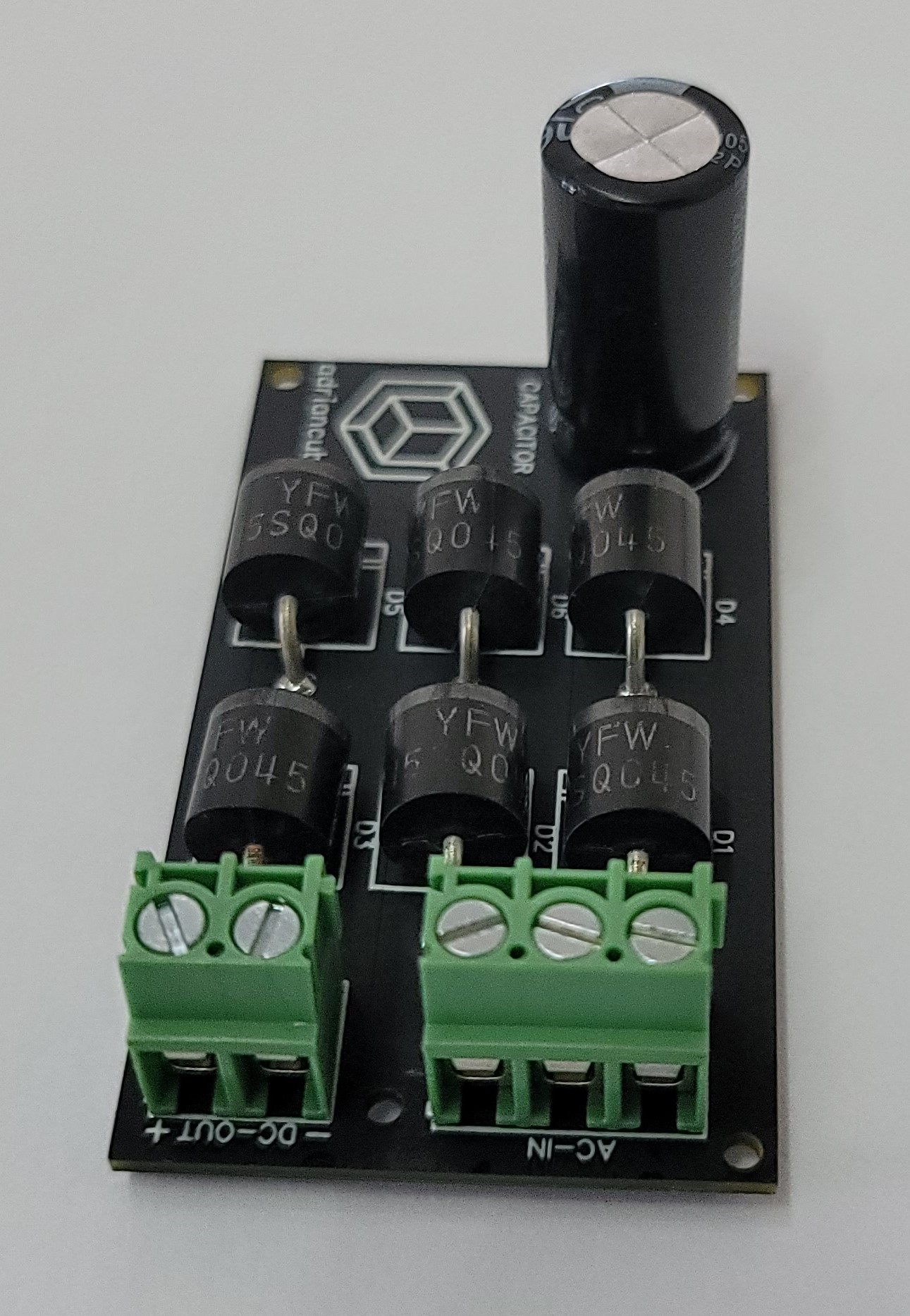
I created a Shottky diode based FW rectifier and then added 2 x  6800uF Caps. Unfortunately The max Voltage I have seen is 1.2 V. There is nothing wrong in your design, my poor choice of motor. I am now printing a new nacelle to connect to a Stepper Motor I have at hand and see what happens.

The great thing about this is that on every step I learn something new which one of the reasons for doing this ! :)

Thank you Adrian !

  Are you sure? yes | no

adriancubas wrote 12/31/2023 at 11:47 point

Hi Andre. I'm so glad you are enjoying and learning every step of the way with this project. Unfortunately, many of the motors have to be rewound to achieve higher voltages. Using sttepper motors is a good option. I suggest you take a look at prototype 1. Good luck!

  Are you sure? yes | no

newkie wrote 12/19/2023 at 07:58 point

How well does this scale? Does it make sense for a stationary design?

  Are you sure? yes | no

adriancubas wrote 12/31/2023 at 11:54 point

Yes it can work as a stationary unit but in that case the design could be simplified. You can scale it up but keep in mind that the blades will rotate at a lower RPM and you will get more torque if you keep the geometry as it is.  

  Are you sure? yes | no

John Lamport wrote 11/07/2023 at 16:22 point

Adrian, I wanted you to know that I've made some good progress with the help of your files. I have some pictures but I don't see where I can attach them. I had to modify the box as my stepper motor is larger, I had already printed out the propellers for prototype 4 so I modified the propeller end part so the blades would fit. I also modified the rotor parts as I had a larger bearing. The problem seems to be that it takes a good amount of wind to spin the blades, is that normal? The larger motor doesn't seem to be putting much of a drag on it. I do have a question about the pitch of the blades. I used your method of putting the blades on the hub then pushing the tips down so they are all of the same plane, It looks like I should have more of an angle relative to the central hub, is there a certain degrees it should be at? I am also going to modify the central hub to use the 4 blades instead of the 3 that prototype 1 has. If I connect a drill up to the motor and spin it at a medium speed, with no load I get 30VDC, I also put a 20 ohm resister across it, mainly because I had a large wattage one but I don't know what the load resistance of a charger would be, and I get 200 milliamps. I'm going to use it to charge 2 18650 batteries in parallel, I might try getting a 5v regulator and just have it feed a TP4056, I'm using a solar panel with that to charge the batteries now. I've enjoyed working on this and hope to get it so it will work for me. Thanks John

  Are you sure? yes | no

juanmaggi wrote 09/28/2023 at 00:49 point

Hi Adrian, Im having a problem with the last files from prototype 4. When opening the blades on the cura slicer the blades are incredibly small. Do you know why this can be? And if so, do you know how much do I have to scale them up? Thanks!

  Are you sure? yes | no

adriancubas wrote 11/08/2023 at 14:21 point
You need to scale the Blade so that its maximum height is 220mm.

  Are you sure? yes | no

John Lamport wrote 09/10/2023 at 17:38 point

Adrian, I am getting back to this project, as your designs will work well for my project, but I am going to make some modifications and need some help from you. I did buy the recommended generator for this version but as we have found out the supplier has changed the generator to one that now does not work. I went back to your earlier design, Phase 1?, the one with the stepper motor and the 3 blades. That will actually be more what I need as it will be a permanent installation, I want it to charge the batteries in a weather station I have. So I don't need the on board battery and I like that in pivots at the center of the motor, that will be more balanced. I also plan on using a set of slip rings for the cable. I have a stepper motor, slightly larger than yours, there is no markings on it so I don't know the actually model. I have connected it to the 2 rectifier bridges and with a drill I get 40 VDC with no load. I would like to modify your files so my stepper motor will fit in the housing. I have the 4 blades from this design printed so I would also like to use those either by modifying that hub or modifying the 3 blade hub to accept these blades. Would it be possible to get your original files so I can modify them in either Fusion 360 or Solidworks? Thank you, John

  Are you sure? yes | no

adriancubas wrote 09/11/2023 at 00:04 point

Wow, I had to search the HDD for the old Windturer files. I found them and posted them at this link. Good to hear from you again John.

https://grabcad.com/library/windturer_prototype_1-1

  Are you sure? yes | no

John Lamport wrote 09/11/2023 at 08:39 point

Adrian, thanks so much for sharing your files with me, very generous of you.  I was able to download the files and open them in edrawings Pro. I received a new laptop in work recently and they did not install Solidworks that I used to have. I am the controls engineer so they may have thought I didn't need it, I will request to have it reinstalled.  Once I get that I should be all set. I will keep you up to date on my progress. Thanks again, John

  Are you sure? yes | no

adriancubas wrote 11/08/2023 at 13:59 point

Hi John,

I'm glad you have made progress on this Project and found my files useful. I don't know if by copying and pasting the photos you made directly into the reply box you can attach your photos which I would love to see. Steppers Motors require relatively high forces to overcome the attraction between the magnets and the stator and make them start to rotate, something known as High Cogging Torque. This is why several Blades are required to generate sufficient Drag during the initial stages of the motion. Remember that Blades with airfoils are only efficient at certain RPM. Generally between 6 and 8 TSR have an appropriate CP coefficient. By this I mean that you need higher angles of attack and/or several Blades to get the system started at low wind speeds. A Variable Pitch would be desirable here but it makes it more complex to build. Try to try an angle of attack of 15-25 degrees. Ideally 5-10 degrees would be ideal but start up will be more difficult. Another negative aspect of steppers is that they have a high internal winding resistance. This causes much of the wind potential to be lost internally in the form of heat. Try placing the batteries directly at the output of the two rectifiers and measure the charging current, that will give you an idea of how long it will take to charge them. I think it would be interesting to create a variation of this Project using large stepper Motors and Blades not so optimized but very easy to build. I have done tests and although it would be a bit big, heavy and inefficient but still with a good charging current in the range of 2A. For those who have the space, maybe it would be very practical and easy to build. See you John, you've been doing this for a long time and your motivation on these topics is the same as mine :)


  Are you sure? yes | no

John Lamport wrote 11/08/2023 at 14:27 point

Hey Adrian

Thanks for getting back to me. I did figure out yesterday that I had set the pitch of the blades wrong. I looked at the directions you have for prototype 4 . You mounted the blades onto the hub and pushed the tips down so they were on the bench and all at the same angle. I did that but I was using the hub from prototype 1, the hub on 4 is about 12mm higher than 1's. So my blades came out fairly flat. I also modified the central hub so I can put 4 blades on it. This time I will use 4's hub to set the pitch and will see if I get them to around the angle you say. Good point about mounting the batteries right at the motor. I was thinking of using it as a more permanent setup but by having the batteries at the motor it also eliminates the problem I've been having of making slip rings. They would also introduce some losses. After I get the new hub and blades set up I'll post my email, you can then send me yours and I'll send you the pictures. Thanks for the advice.  

  Are you sure? yes | no

John Lamport wrote 03/27/2023 at 14:23 point

This is disappointing, I was finally able to get my blades printed out and back to this project and was checking something and saw the comments about the replacement generator. I also bought mine back in November and have tested it and only get 1 volt out of it. I did watch the Great Scott video about rewinding a BLDC but that's more than what I would like to get into. Are there any other alternatives? Thanks John

  Are you sure? yes | no

adriancubas wrote 03/27/2023 at 22:28 point

Hi John,

Unfortunately, if you want to keep that generator, you will inevitably have to transform it in order to achieve higher voltages. You can replace the magnetic strip with stronger neodymium magnets or increase the number of turns on each stator pole. I found this Winding Scheme Calculator and it seems very good to determine the different configurations of this type of motors (generators), when you want to change their electrical properties. I have tried it during the transformations of the winding of a Drone M600 electric motor and it has hit the spot.
https://www.bavaria-direct.co.za/scheme/calculator/
I recently published a Log where Gimbals motors are used and the results are very good without having to do this type of transformation.
https://hackaday.io/project/185070-3d-printed-portable-wind-turbine/log/216751-new-changes-to-windturerp4
Another option would be to use a stepper motor like the one used in Prototype 1.

  Are you sure? yes | no

John Lamport wrote 03/28/2023 at 09:36 point

First off thank you for your quick reply, as you have in the past, it's much appreciated. As I'm sure I could rebuild a BLDC motor it's more than I was hoping to get into for this project. Fortunately, unfortunately, I have several other projects I'm working on and a long list of others. So most of my projects are in some stage of completion and this would just get added to the shelf. I do like this design and do want to do something with it, as mentioned in one of my first comments back in November I'm looking at using this in a more permanent application and asked about slip rings, I may look into an alternative project. Staying with this one for now what voltage and wattage do you think you need to charge the NP-F970 battery? You have obviously done a lot of research and engineering on this and was wondering if you have looked at, or what your thoughts are, on this generator I found on Ebay, https://www.ebay.com/itm/314278621717?hash=item492c773215:g:AsgAAOSw9wJjnXDo&amdata=enc%3AAQAHAAAA4LCwpLI6cCMB3Y7%2FGQcRI6N3xTVJl0jqI5G1SqoZsJ2jpd1AHKEoJSgQB1onZOZiLJ9g%2FyKQRPkZijD3bcjZEIh4xbgBEKohCp59Lh4d8kaaFKRR3T%2FWgGSoSVWie1ZxKfRmCbLTYLuYKs6r10eCJ0WmcZ4zDzVwzhFinHXmGcusmpd9AHaoP71HSCXmR0yrZfqcSFmaoZDUfyc8044DzSZtgyF9cSh8pV10NISQSb4%2BPvjdIuoa%2FTs0AMp7LVzsqELfoWmgrS5%2FnnzPPhDo3I%2BcTbvzH7N4CUhTQZo9FvHy%7Ctkp%3ABFBMrs68-ORh, this one is 24 watts. Thanks again, John  

  Are you sure? yes | no

adriancubas wrote 03/28/2023 at 15:14 point

The operating voltage of an 18650 battery ranges from 6V to 8.4V. Suppose the battery is in an intermediate state of charge and its voltage is 7.4V. If we apply a voltage greater than this value, a current should flow into its chemical structure and the charging process should begin. Now, to know how much energy flows to the battery in an instant, we should also know the intensity of the circulating current and the charging time. Energy=Voltage*Current*Time

Keep in mind that you can have a voltage of 10V applied to this battery from a BLDC generator with a Bridge Rectifier, but if the windings of the generator are made of very very fine copper wire, the current intensity is going to be very small. Also the torque that the propellers will have to make would have to be greater to maintain this voltage. Another aspect is that when the wind turbine blades are not rotating, you do not have the advantages of the aerodynamic thrust, so the desired generators must be able to start with very low torque. Also the outer dimensions of this generator are not clear to me.

It is a fairly complex phenomenon and there are many variables to keep in mind.
Regarding the Ebay link that you sent me, I have my doubts that it could be a good generator for these purposes. I would have to test it experimentally. I am inclined to think that it will not work. An RPM value of 1200RPM at 310V DC appears on the label. If my calculations do not fail then if we use it as a generator at 250RPM we would obtain approximately 65V, it seems exaggerated to me and if so, the wire gauge must be very thin (high ohmic resistance). Further down in the description it appears that 9V at 120RPM can be obtained, but the calculations do not match.
I hope I have clarified some doubts,
Best
Adrian

  Are you sure? yes | no

John Lamport wrote 03/28/2023 at 15:25 point

Again thanks for the quick reply and for looking into that generator. I figured it wouldn't be that easy as to find something on Ebay. I have a couple of stepper motors so I'm going to see what I can get out of these. I just connected one of the stepper motors, using 2 bridge rectifiers connected in series I get 50 VDC with no load using a drill at a slow speed. I then connected a 20 ohm, 50 watt resistor across the DC output and with the same drill speed and get 2.5 VDC across the resistor, or 125 mA. Check me on that but do you think this will be usable?  Thanks John

  Are you sure? yes | no

tlum2 wrote 01/24/2023 at 13:56 point

While I do think this project was incredible to watch, I would not recommend anyone thinking they can recreate this themselves with the BOM as it stands now. I understand parts change and projects get modified along the way but after ordering all the items back in November, waiting for everything to arrive, building my own rectifier and trying the solid state version as well, the project is essentially a very complicated way to make about 1 volt of power. I have the Windturer running quite quickly in front of a larger sized fan and it is spinning freely and the best it can do is about 1 volt. I hooked another one of the BLDC motors to my 1800 rpm Ryobi drill and it produces about 7.5 volts at full speed with the scratch built rectifier and 5.4 volts with the solid state one also in the BOM. The potential is there but I cannot imagine any scenario where you could find enough wind to generate that kind of rpm and I would not be comfortable standing anywhere near those blades going that speed.

I had a fun time building this project but it will unfortunately go on the shelf until components are sourced that can produce the required voltage.

  Are you sure? yes | no

adriancubas wrote 01/25/2023 at 03:30 point

Hi tlum2,

I am currently working on some modifications to use a new low KV BLDC generator, which does not require modifying the motor stator windings and which I will include in the bill of materials. In a future LOG I will detail the whole process.
The low voltage obtained by you I attribute to the unmodified BLDC generator that you used in your Windturer and that is derived from the link to the purchase website that I initially included in my BOM.
I want to reiterate that the version of the motor (Generator) that I obtained in the early stages of development of this project, differs from the unit that I recently purchased and shipped to me. Apparently the one you also bought in November has the same drawbacks. They have replaced ceramic magnets with magnetic strips, leading to smaller variations in induction magnetic flux during generation, leading to low induction voltages.
    Even with the original version of the generator, it required changing the number of turns of wire on each of the poles from 30 turns to 80 turns. I made the star connection. There are several records where this is alluded to. These generators were not conceived as such but as motors. In many cases it is impractical to design a motor that turns at very low RPM and the manufacturers know this as the applications would be very limited. That is why the common kv values of these motors are much higher than what we need in the Windturer (25-45KV). The most common values are higher than 260KV.

  Are you sure? yes | no

tlum2 wrote 01/25/2023 at 13:16 point

I totally understand that the parts have changed and still require modifications. I look forward watching this project continue to evolve and wish you the best of luck. Thanks for your time and effort.

  Are you sure? yes | no

thespeakgeek wrote 01/19/2023 at 00:27 point

Can you share more details on the rewinding you did on the BLDC motor? I didn't realize the BLDC motor had to be rewound when I built mine. I used the stock motor from Aliexpress and I could barely get enough voltage from it to light an LED. I found the log where you talked about rewinding with 80 turns of wire per segment of the stator. Are you using multiple wires together? I have the 36 gauge wire from the bill of materials and it is very thin. I started rewinding the stator to get a feel for the technique involved. It feels like I need to use multiple strands of wire in order to handle the current. Sorry if the details are obvious to others, I don't have much experience with electric motors. I have watched the YouTube video by GreatScott! on rewinding a BLDC motor as a Generator, so I understand the principles. I would just like to know more specifics of what you used for your rewinding.

  Are you sure? yes | no

thespeakgeek wrote 01/19/2023 at 19:33 point

Looking back at the photos and the project log from 9/17/2022, it mentions using 80 turns of .35mm wire (~28 AWG) being used. In the Bill of Materials it calls for 36 AWG wire. Was this just a mistake in the Bill of Materials?

  Are you sure? yes | no

adriancubas wrote 01/23/2023 at 15:51 point

Yes that's a mistake, 36AWG is too thin . I also fixed that. Thanks

  Are you sure? yes | no

adriancubas wrote 01/23/2023 at 15:50 point

Hi there,

I ordered a new BLDC unit from the link I shared and it doesn't exactly match the one I originally purchased. The most worrying thing is that they have replaced the magnets with a magnetic strip similar to those used in the joints of refrigerators. Although winding these new units can certainly bring the kV value down from 260 (calculated by me) to a lower value, I still have doubts that it is an effective generator. I have just removed my recommendation towards the buy link for this generator on Aliexpress as I cannot guarantee the quality of the products they deliver compared to what I originally purchased.
Currently I am characterizing other BLDC motors to adapt them in my design. The best option so far that I have found are the BLDC motors used in Gimbals. I am currently studying the IPOWER GDM5208 and I think it meets expectations. They are a bit more expensive, but there are no other options that I have found viable. Something that I wish was different is regarding the gauge of wire used, which is very thin. This causes the ohmic resistance to be 10-15 ohms per phase.
https://shop.iflight-rc.com/ipower-motor-gm5208-12-brushless-gimbal-motor-pro279
https://aerialpixels.com/shop/motors/brushless-gimbal-motors/iflight-rc-ipower-brushless-gimbal-motors/ipower-gbm5208-180t-brushless-gimbal-motor-dslr/
This motor has a kV value between 30-45 depending on the variant. There are two models, one with 24 poles and the other with 12 poles. I think the 12 pole variant has slightly better performance for this purpose.
Another option would be skateboard hub motors, although I think they would be a bit heavy. I would have to try.
If you want to rewind the BLDC I suggest you this video by Great Scott on this subject https://youtu.be/KZ4cylB114E and read the related log in my project.

Best,

  Are you sure? yes | no

John Lamport wrote 01/04/2023 at 18:41 point

I haven't been able to get access to the printer I need for the blades, I should soon, everything else is fitting up nicely. I have a question about the blade length, earlier you said the blades should be a maximum of 220mm does that include the tenon that goes into the blade ends on the hub or just the blade length? Thanks John

  Are you sure? yes | no

adriancubas wrote 01/04/2023 at 21:24 point

Hi John,

It is the total length of the blade, including the mating tang. Some Ender 3 type printers cannot print more than 220mm vertically.

  Are you sure? yes | no

John Lamport wrote 01/04/2023 at 21:47 point

I'm getting checked out on a Ender 5 at the Makers Space I go to. I didn't think of that, you print it vertically from the tang up, that makes sense, less support marks, Thanks

  Are you sure? yes | no

John Lamport wrote 12/18/2022 at 10:11 point

I've started to assemble mine, so for all the files, with a minimum of sanding, fit great. I have two questions, Did you cut the shaft on the generator as mine is to long to fit into the spacer? What diameter and length is the tube for the tail? Thanks

  Are you sure? yes | no

adriancubas wrote 12/18/2022 at 14:36 point

Hi John,

You must cut the surplus of the motor shaft. In my case, the generator they sent me had a shorter shaft and I didn't need to do this. I believe that all those who ship now already have the longer shaft and I have also seen that they have changed the grip plate for a flatter one that is less thick. As for the tail tube, I used a 12mm OD carbon fiber tube, which I had left over from a drone I made in the past. The length of this tube can be much longer than what I put in the CAD. In my project I used one of approximately 100mm. I hope I have helped you.
Best

  Are you sure? yes | no

John Lamport wrote 12/18/2022 at 18:10 point

Thanks for getting right back to me. I figured I'd cut the shaft, it's not needed for anything, but just wanted to check to make sure I wasn't looking at the assembly wrong. Thanks for the info on the tube. I'm going to have the piece that the tripod screws into machined. I think you're right and that will get a lot of wear, also the threaded hole didn't print right, it's to large for my Tripod, the tripod has the standard 1/4 bolt and looking at your drawing that should be the right size so I think it's more of a printing issue. Thanks again

  Are you sure? yes | no

Stephen Wolff wrote 12/02/2022 at 01:15 point

Problems with the blade stl  in the P4 folder. Opening in Cura displays it as incredibly small. A message displays saying it auto scaling it 10000% of its original size. Another error window opens in Cura saying that "the highlighted areas indicate missing or extraneous surfaces". Anyone else seeing this?

  Are you sure? yes | no

adriancubas wrote 12/02/2022 at 03:26 point

You must scale the Blades so that their maximum height is 220mm. They were generated in QBLADE and I seem to remember that the software exports them in a 1mm scale.

  Are you sure? yes | no

Stephen Wolff wrote 12/02/2022 at 18:29 point

The scaling worked great! I'm not sure if this will prevent me from printing, however, Cura still gives me the "Model Error : "the highlighted areas indicate missing or extraneous surfaces. Fix your model and open it again in Cura." The highlight is on the "bottom" of the blade. Assuming you print aligned from the blade root on the bed with the tip at the top of the z-axis.

  Are you sure? yes | no

Stephen Wolff wrote 11/23/2022 at 18:09 point

I am trying to print this in PETG. I sometimes have issues printing threads in any material getting them to work. Is there any suggestions on print parameters, material, post processing for printing threads that work? Does everyone wind up sanding them until the screw works?

  Are you sure? yes | no

John Lamport wrote 11/26/2022 at 08:48 point

I also printed in PETG, I sanded the top edge but just to take the sharp edge off so it would be easier to start. I then take a small paint brush and put some liquid soap on the thread, acts as a lubricant, thread was a bit tight at first put go back and forth a few times and it was fine. 

  Are you sure? yes | no

Stephen Wolff wrote 12/01/2022 at 02:21 point

Thank you! I also calibrated the printer really well and printed at 0.15 layers. I am now looking at the STL for the blades themselves and they seem to be incredibly small. Is there a separate file for those?

  Are you sure? yes | no

John Lamport wrote 11/17/2022 at 19:46 point

I have started to print the parts and will be ordering the generator and other parts soon. I see that the battery comes with overvoltage, low voltage and all the safety features. I will start with this battery but will also expand to others, 3.7 V Li-ion for example. Do you have any thoughts on regulator/protection type of circuit? Thanks John

  Are you sure? yes | no

adriancubas wrote 11/18/2022 at 13:21 point

Did you read my mind? LOL. I am working on a new 3-4.2V battery where I cover how to recover 18650 cells from broken laptop batteries etc. I think having a choice of batteries in this voltage range will make it possible to charge them even if the wind speed is low. There are not many suitable BMS options for a parallel array of these types of batteries. I found this option and so far it has turned out to be effective

https://amzn.to/3V10tlG
I am working on the modeling of the casing. As soon as I have everything ready I will publish a Log. Best

  Are you sure? yes | no

John Lamport wrote 11/19/2022 at 10:14 point

Ha  Ha, not a mind reader as much as we think alike. Plus it's a natural progression for your device. As mentioned earlier I want to use your generator to replace a solar panel on a weather station I made. The station has a ESP32 with a single 3.7V Li-on battery, It uses a TP4056 charging module but the board you showed would work as well, I'll check that out. Do you think the TP4056 would also work? I have the ESP32 sleep for 15 minutes, send a reading then back to sleep.  The battery now is good to get it through the night, and if it's a sunny day will recharge, if it's a cloudy day it does not last 24 hours, the wind generator should solve that problem. Having parallel batteries would be a good advantage, I look forward to see how you make out. Thanks

  Are you sure? yes | no

adriancubas wrote 11/22/2022 at 17:38 point

The main limitation that I see in the use of the TP4056 modules is that they only support a maximum of 1A of charging current. I believe that this value can be exceeded by the wind turbine in favorable wind conditions. When this happens, the module interrupts the charging process and the rotor RPM can increase dangerously. You could place 2 or more 18650 cells in parallel but each one with a TP4056 module.

  Are you sure? yes | no

John Lamport wrote 11/23/2022 at 15:30 point

Good point, what do you estimate the max current out would be? The charger you reference above is good for 10 amps, so I'll assume the generator is less than that. I have most of the parts printed and have ordered the others, should have it all in a couple of weeks. As mention I want to modify this for a permanent installation so I need to add a split ring assembly. I do like your method of having the battery as part of the generator, such a good design, eliminates other problems. I have ordered the battery and will first make mine as yours is. Thanks for getting back to me, John

  Are you sure? yes | no

adriancubas wrote 11/23/2022 at 18:58 point

The maximum current is usually below 3A-4A, with winds of no more than 28km/h and charging batteries in this voltage range 3-4.2V. The module that I suggest can comfortably handle this value, not so much the TP4056.

I don't think you need slip rings. The wind almost always blows from a specific direction in each region. Keep this in mind and place the wind turbine pointing at that area. Wrap the cable 2 or 3 times around the mast and tie it down. Leave room for the cable so that it can rotate 360 degrees.

  Are you sure? yes | no

Open Green Energy wrote 11/10/2022 at 06:04 point

Congratulations man!

You deserve this. I am very much interested to make one for myself. However, Aliexpress is banned in India that's why I can't purchase that BLDC generator. If you can buy one and send it to me, I am ready to pay you.
Thanks, Cheers !!

  Are you sure? yes | no

adriancubas wrote 11/10/2022 at 17:36 point

Thanks for your comment. Although I have obtained the Prize, I do not intend to abandon the development of this project. I have new modules in mind that I couldn't implement because I ran out of time lol. Another thing I want is to design my own generator from more accessible elements. I tried to buy new generators (motors) and I already notice an increase in their price, I also do not doubt that the stock will run out and we will have to wait. I will propose new solutions.:)

  Are you sure? yes | no

John Lamport wrote 11/09/2022 at 18:08 point

You mentioned in the description that you are a finalist in the Hackaday prize, I just got my email from Hackaday and you are the Grand Prize winner. Congratulations! Well deserved, a great design and a useful device.  

  Are you sure? yes | no

adriancubas wrote 11/10/2022 at 17:28 point

Thanks John!!!

  Are you sure? yes | no

Tom wrote 11/09/2022 at 17:03 point

 A M A  Z I N G

  Are you sure? yes | no

adriancubas wrote 11/10/2022 at 17:38 point

Thanks Tom!

  Are you sure? yes | no

James Newton wrote 11/07/2022 at 18:25 point

So... I did say "shut up and take my money!" The question is, are you, or anyone else, willing to build one and ship it to Escondido, CA? And for how much? I'd love to build one, but I just don't have the time. If I buy one, I LOVE that I could potentially repair it if damaged because the files are available. I really think this is a viable product, and being customer #1 (or near) would be an honor. 

  Are you sure? yes | no

adriancubas wrote 11/07/2022 at 20:28 point

The honor is mine! It would take me a while to wait for a new generator to arrive from China and modify it, but rest assured I will build you one and give it to you. I'll let you know when it's ready!

  Are you sure? yes | no

James Newton wrote 11/07/2022 at 21:15 point

Very kind offer, but as a judge I literally can't accept a gift. LOL. Let me know what the actual cost is and I'll happily pay it when it's ready. 

  Are you sure? yes | no

John Lamport wrote 11/07/2022 at 14:32 point

Great, design for this and your previous one. I'm looking at using this in a more permanent application, I currently have a remote weather station that has a 3.7 V Li-on battery and a solar charger, only takes one day of rain and the battery is dead. As you say the wind is always blowing. Do you have a slipring design for this one or the previous? Thanks

  Are you sure? yes | no

adriancubas wrote 11/07/2022 at 17:09 point

I don't have it, it would have to be designed

  Are you sure? yes | no

John Lamport wrote 11/07/2022 at 17:25 point

Thanks for getting back to me so quickly, I really like the work you've put into this, I'll see if I can fit a slipring onto it. Thanks again

  Are you sure? yes | no

James Newton wrote 11/07/2022 at 18:23 point

John or Adrian, if you do a slip ring version, I would really like to see it. This unit is light enough that I might be able to get away with putting them up on my house or yard without my neighbors complaining. ,o) Then if I go camping or even on a cross country road trip, I can take the with and use them to charge cell phone, provide light, etc... And show them off to everyone. LOL. 

  Are you sure? yes | no

sebastien.foulquier wrote 10/21/2022 at 15:06 point

Hi, great project! I have downloaded and printed most parts of prototype 1 some time ago and I can't retrieve the instructions/ilst of material for this prototype... Could you send them by any chance? that would be great!  I am sorry, I only figured out recently that there was now a prototype 4!... I'd like to start with 1 and maybe later go for the latest version. Thanks a lot!

  Are you sure? yes | no

adriancubas wrote 10/22/2022 at 02:17 point

I have a copy of the Prototype 1 BOM and Instructions on my Instructables page. I knew this could happen lol

https://www.instructables.com/HOW-TO-MAKE-a-PORTABLE-WIND-TURBINE/

  Are you sure? yes | no

Michael Bravo wrote 08/03/2022 at 15:03 point

What are your design expectations on mounting the turbine in a lightweight "adventure" usage scenario? Just use a stick? :) Photo tripod should probably do, but not everyone has one with them.

  Are you sure? yes | no

adriancubas wrote 08/03/2022 at 15:20 point

Haven't given it much thought yet but I think a viable alternative would be an extension pole, ropes and ground anchors.

  Are you sure? yes | no

Similar Projects

Does this project spark your interest?

Become a member to follow this project and never miss any updates