 Nick Bild
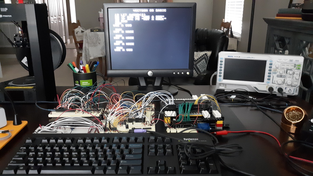
How It Works
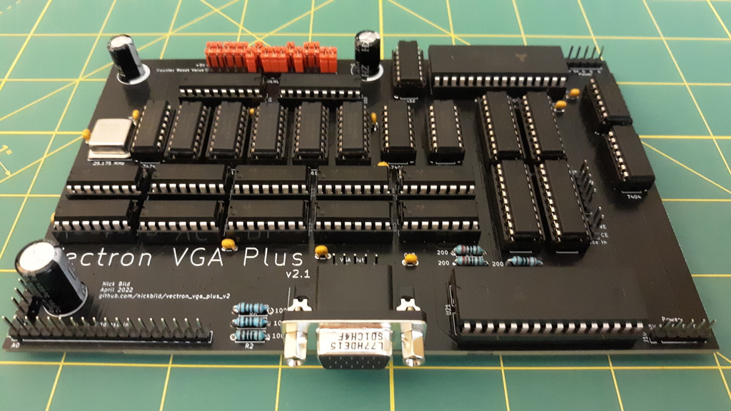
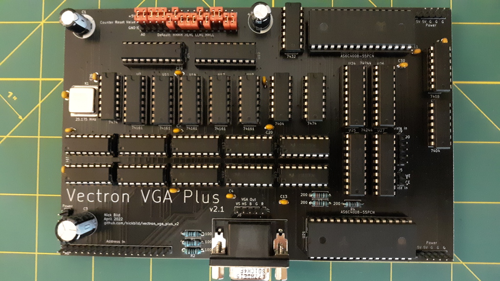
Vectron VGA Plus v2 is an improvement on the earlier design.
The key to the simplified design of the Vectron VGA Plus boards is to use more RAM and less logic. So, for example, instead of having counters and flip flops, etc. to time each horizontal sync, that logic is embedded in the data in memory. Memory addresses are sequentially incremented by an osciallator, and the contents of each memory address specify what signals to output (R/G/B/H sync/V sync). Each of these memory addresses correspond with a specific pixel location (both visible and invisible) on the display. When the end of a frame is reached, the address counters are reset, and the process starts all over to draw the next frame.
This second version offers a number of enhancements over the original:
- First, a second RAM chip was added to the design. This allows for an active/standby scheme, such that the standby chip can receive updates without interupting the active chip that is displaying the video output. When the host is done writing, the chips automatically switch roles in an instant, which updates the display without interruption.
The original version used a single RAM chip, which led to momentary blips in the display during writes. This new type of design would have been simpler to achieve by using dual-port RAM, but in the world of DIP chips suitable for retro projects, I couldn't source anything above about 4K, and I need a 256K chip for my selected resolution, so that wasn't a reasonable choice.
- The memory address at which the counter resets is no longer hard-wired. It can now be tweaked by setting jumpers at the top of the board, which allows the signal to be fine-tuned, or even an entirely different resolution to be produced. Since the storage of output signals in RAM offers total flexibility, it makes sense to allow for a frame of any number of pixels (up to the maximum allowed by RAM size).
- The size of the PCB was reduced significantly, and lots more capacitors were added to ensure perfect stability of signal under all conditions. Additional power ports were also added to allow for grounding between additional peripherals.
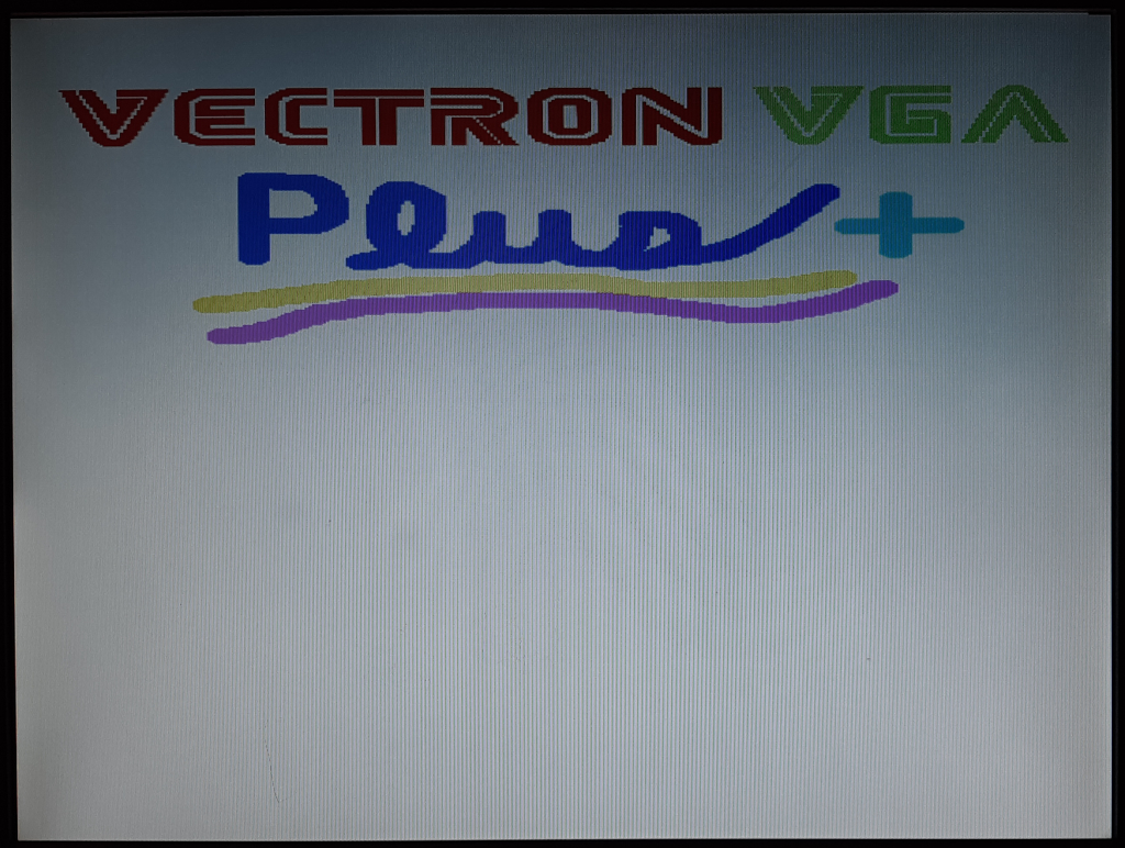
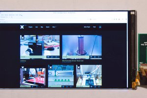
To display graphics with the device, it first needs to be initialized with a blank screen (i.e. setting all the appropriate H syncs and V syncs), then pixels are written by setting the address pins to correspond with a pixel on screen, and the data pins to the RGB value, then issuing a simple latching signal. The details are made clear in the Arduino sketch that can be used to test the board out. The tester will produce the following display output:
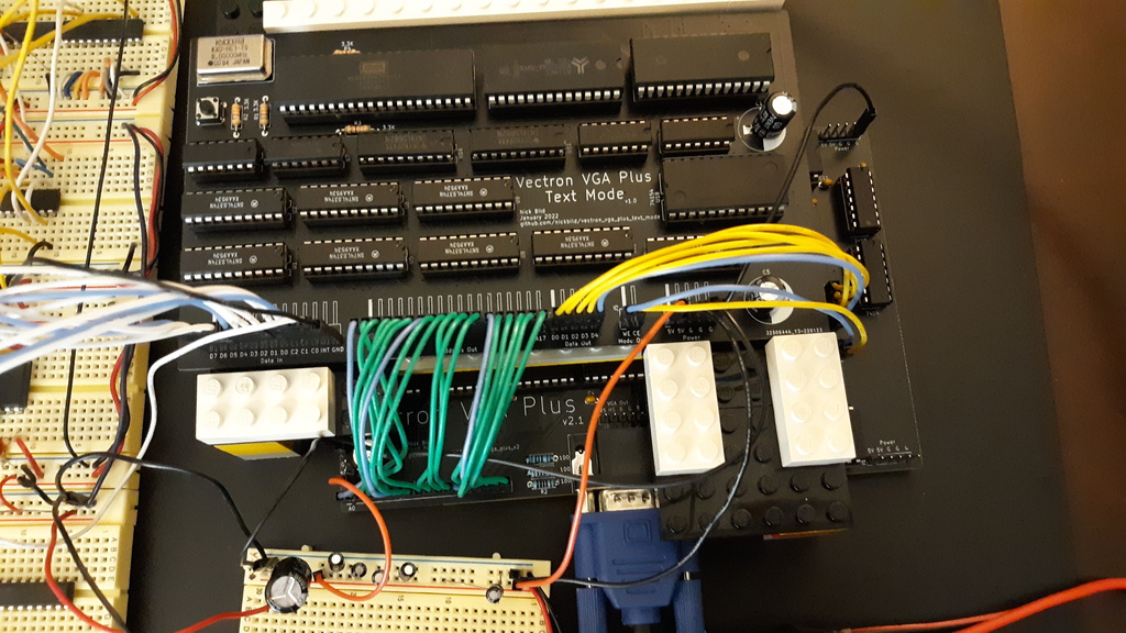
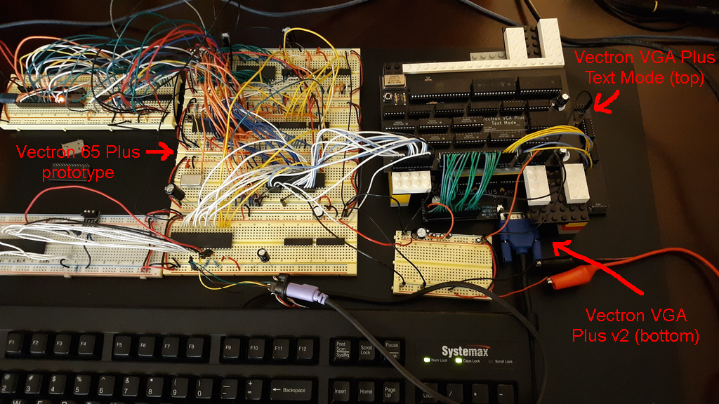
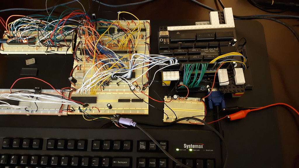
In the examples to follow, I have hooked Vectron VGA Plus v2 up to Vectron VGA Plus Text Mode, which I use to simplify drawing characters to the screen. The Text Mode module is in turn controlled by a breadboard prototype of the Vectron 65 Plus 6502 CPU-based computer (a PCB of this prototype will be created in the near future).
Media
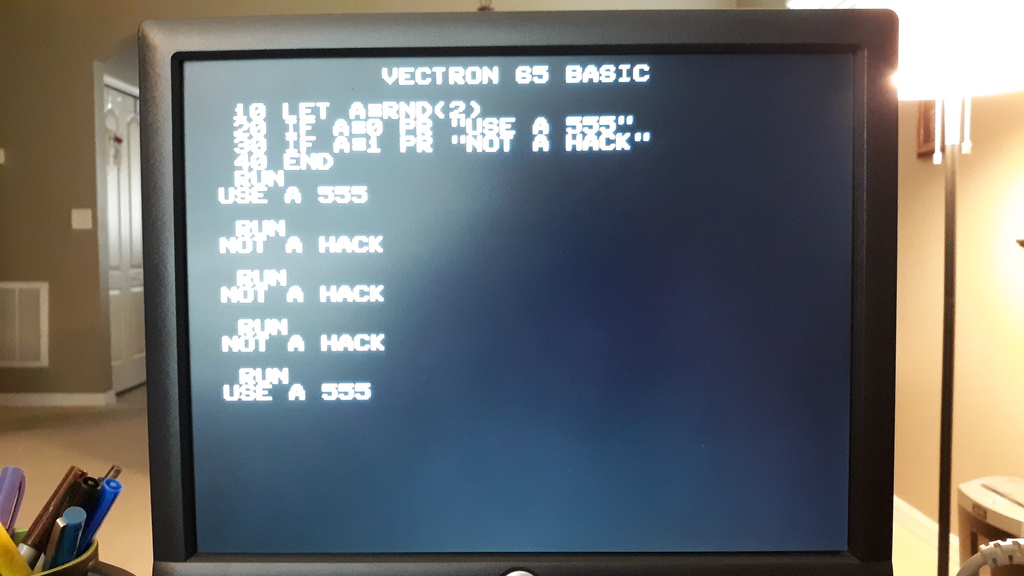
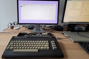
Save time with a Hackaday comments generator, requiring only four lines of BASIC:
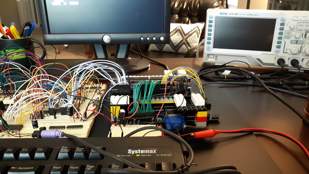
Here is the Vectron 65 Plus computer breadboard prototype (soon to be a PCB) interacting with the Vectron VGA Plus Text Mode board, which in turn uses the Vectron VGA Plus v2 board to display a VGA signal:
Vectron VGA Plus v2 circuit diagram:

Bill of Materials
- 1 x 25.175 MHz crystal oscillator
- 2 x 74LS682
- 1 x 74AC32
- 1 x 74AC08
- 2 x AS6C4008-55PCN SRAM
- 2 x 74AC74
- 5 x 74AC161
- 2 x 74AC04
- 4 x 74AC244
- 10 x 74LS157
- 3 x 1000 uF electrolytic capactitors
- 30 x 0.01 uF ceramic capacitors
- 3 x 100 ohm resistors
- 3 x 200 ohm resistors
- 1 x VGA adapter
- 2.54" spaced male header pins
- 2.54" spaced jumpers
- PCB (KiCad Design Files)
About the Author


 István Hegedűs
 Dave Henry
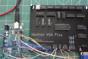
 twl
twl
>> main thing is to figure out best way to read/write the memory from CPU (for setpixel(), readpixel()) when the memory output is busy all the time generating both the video control signals and the pixels.
Definitely, that's why I went with 2 RAM chips and an instantaneous chip-flipping scheme that doesn't interrupt the output. Interested to see other solutions to this problem.