 Leonardo Ward
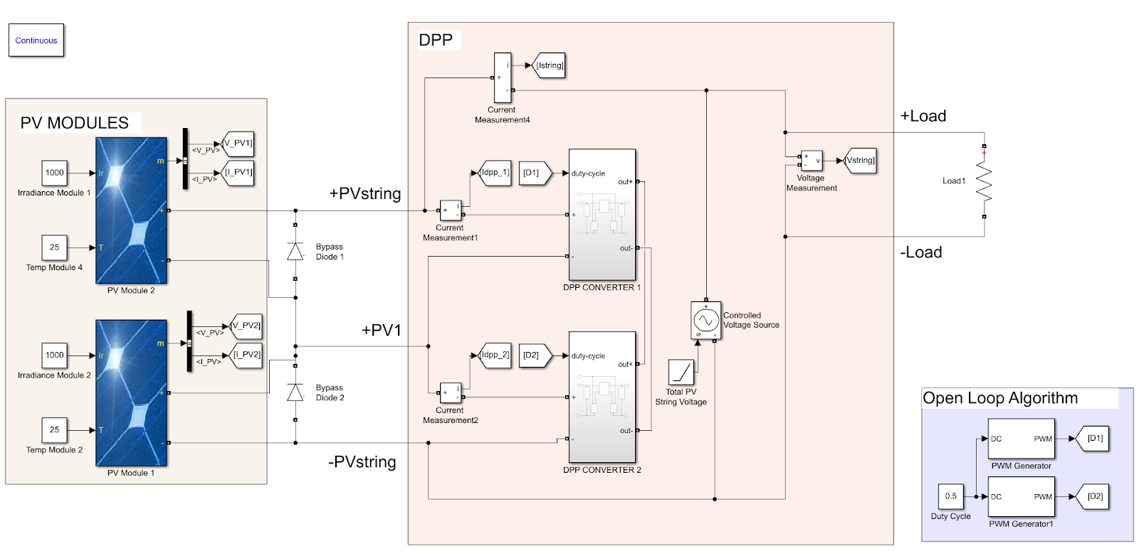
Before working on the circuit design of the MPPT it is a good idea to simulate the PV system and create a preliminary proof of concept. The software used to simulate the system is Matlab Simulink. All the related scripts can be found in the following repository.
The objective of the simulation is to test the DPP architecture used in the MPPT (Chu 2017) and verify that it works correctly. With the simulations we can visualize the benefits of using an architecture with multiple inputs vs a single input under different circumstances.
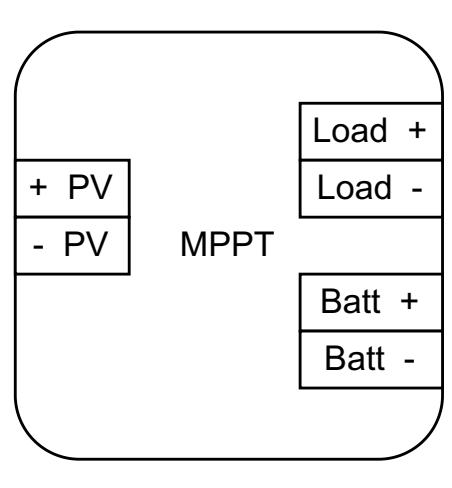
The typical interface for a charge controller has 6 terminals: 2 for the PV, 2 for the load and 2 for the Battery. Of course, more elements can be connected to those terminals (e.g. an inverter).

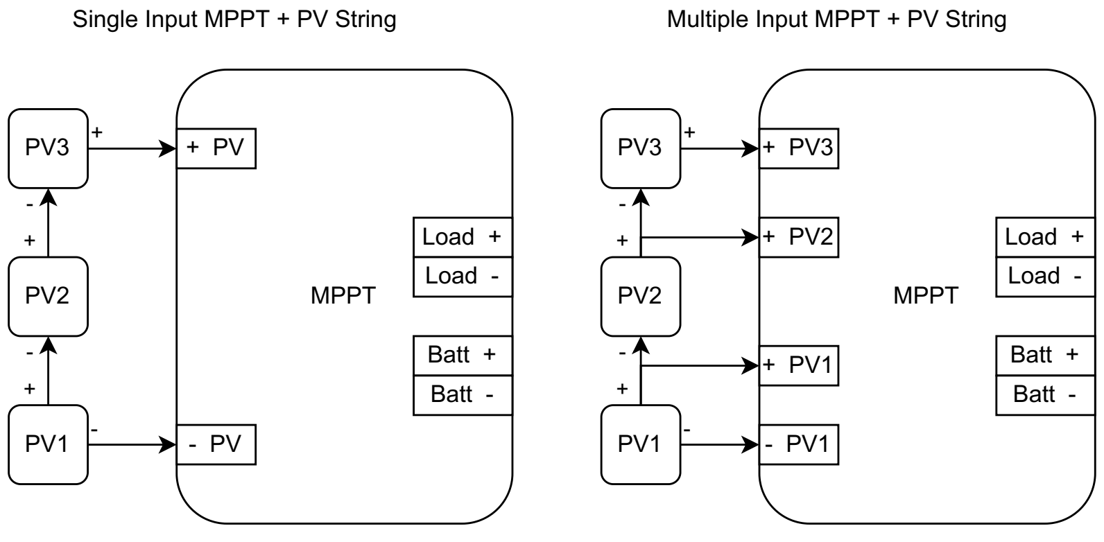
Multiple Input configuration for the MPPT
The simulation contains 2 PV modules connected in series, and the design of the MPPT contains multiple inputs, so we can connect the positive terminals of the PV modules 1 and 2. But we can also disconnect +PV1 and use the typical connections +PV and -PV present in the single input MPPTs, which are being used widely in the market.
Single Input configuration for the MPPT

In the first test both PV modules receive the same irradiance (1000 W/m2). The following images present the Power(W) vs Voltage(V) and Current(A) vs Voltage(V) curves.
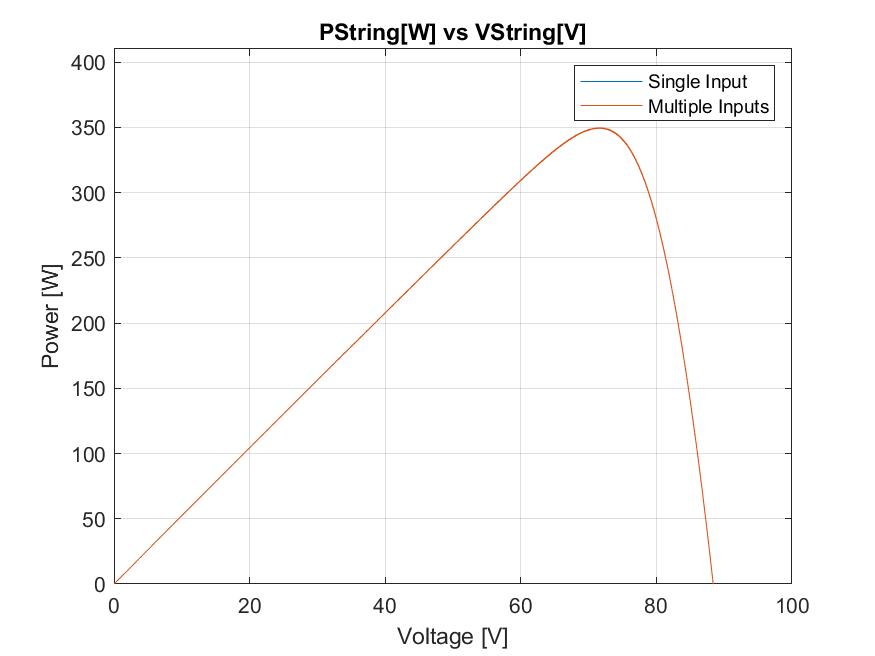
The graphs show that the MPPT is working correctly, also, it is possible to observe the same performance for the single input and multiple input configurations, or at least is close enough that more tests would be required to separate the results.
Test 2 - Shading on one of the PV modules
In this test the PV module 2 receives an irradiance of 1000 W/m2 and modele 1 receives an irradiance of 250 W/m2 (shading). The following images present the Power(W) vs Voltage(V) and Current(A) vs Voltage(V) curves.

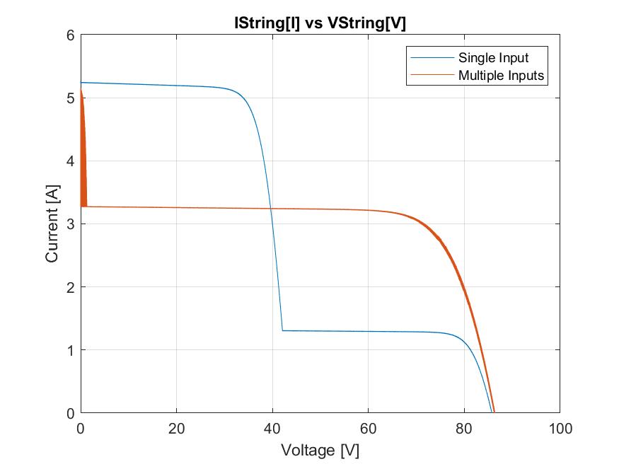
In this test we can observe the benefits of having an architecture with multiple inputs for PV arrays. Looking at the power graph we can observe the two local maximum points, which suggests a performance that is not consistent where the MPPT is focused on a local maximum point. The results from the architecture using multiple inputs suggest a significantly better performance, which validates the hypothesis that the device has an improved performance compared to other charge controllers found on the market that only have single inputs when we consider cases with some amount of shading.
Now, looking at the results it is possible to argue that it is a problem with this architecture, but the results are consistent with other results observed on similar architectures under shading conditions. Maghami (2016) discussed how the performance is affected by shading conditions, for more information about it check the research from Maghami (2016) or check the later post “Increasing the efficiency under shading” discussing design decisions and the benefits of multiple input MPPTs.
References:
Chu, Guanying & Wen, Huiqing & Jiang, Lin & Hu, Yihua & li, Xingshuo. (2017). Bidirectional flyback based isolated-port submodule differential power processing optimizer for photovoltaic applications. Solar Energy. 158. 929–940. 10.1016/j.solener.2017.10.053.
How to wire solar panels in series vs. parallel. (2022). Retrieved 27 April 2022, from https://www.solarreviews.com/blog/do-you-wire-solar-panels-series-or-parallel#:~:text=Putting%20panels%20in%20series%20makes,window%20requirements%20of%20your%20inverter
Maghami, Mohammad Reza & Hizam, Hashim & Gomes, Chandima & Mohd Radzi, Mohd Amran & Rezadad, Sina & Hajighorbani, Shahrooz. (2016). Power Loss Due to Soiling on Solar Panel: A review. Renewable & Sustainable Energy Reviews. 59. 1307-1316. 10.1016/j.rser.2016.01.044.
Panel, 1. (2022). 175 Watt Monocrystalline Solar Panel. Retrieved 27 April 2022, from https://www.renogy.com/175-watt-monocrystalline-solar-panel/
Discussions
Become a Hackaday.io Member
Create an account to leave a comment. Already have an account? Log In.