 Ruediger F. Loeckenhoff
***SCOPE***
We want to provide a very cost efficient control unit which is capable of tracking solar panels to the sun with a high precision even with imprecise solar tracker mechanics. In particular it tracks concentrator photovoltaic (CPV) modules that require a tracking precision of 0.1 degrees. With this work we hope to contribute to the clean energy transition.
***PROJECT STAGES***
A first version of this control is based on an arrangement of breakout boards. Follow the links to Github www.github.com/solhunter to find detailed building instructions and the source code (MIT license).
In the second project stage we have integrated the components of the first stage on a single board. We have received and successfully tested 25 pcs of a refined version V2.0f of this board. You can find the complete design files and CAM outputs in this reposit at hackaday (MIT license).
As a side activity we are promoting the board for general robotics – either as an integrated Arduino compatible ATMEGA328 controller board or as an I2C device that can extend the capabilities of e.g. a Raspberry Pi.
***THE STORY***
Typically, tracker controllers are control cabinets with cables running to limit switches and encoders which are notoriously unreliable as the cables degrade in the UV light or the sensors get flooded with rain. A failed sensor or encoder may make the tracker run beyond its limits and self-destruct. Furthermore, the control cabinet gets into the way of the moving generator. I have even seen trackers running on a central PC connected to two Siemens SPS or at least running on a one board PC. What a waste of money, resources and electric energy.
Now imagine what a “mature” solar tracker controller would look like. Think of the solar tracker as a dishwasher. There would be a small circuit board somewhere in the housing with not much more on it than a µC, some FETs and possibly some extra sensors. But this control didn’t exist. Someone had to make it, so I started this job. I had no idea about microcontrollers but I knew about solar trackers. Now I know about microcontrollers too, and it is great fun. Thank you, Arduino community. As I moved along, I learned about the MPU9250 9-axis compass and figured out that it would be perfect for the astronomic tracking without any external sensors. The real challenge was the self-calibration routine but I successfully solved this riddle. It even works on trackers with an extensive amount of magnetic steel as I confirmed when I was allowed to test one of the prototypes on a 10 m2 CPV tracker for a day. You can find Arduino code and the detailed building and operating instructions at www.github.com/solhunter.
Even so this assembly of breakout boards works very well, it probably wouldn’t be considered a professional solution and I don’t have any experience in circuit board design. So, I greatly thank Ermanno Antonelli for joining forces with me. He is a professional in electronic board design and invested many hours in this project to come up with the present board design.
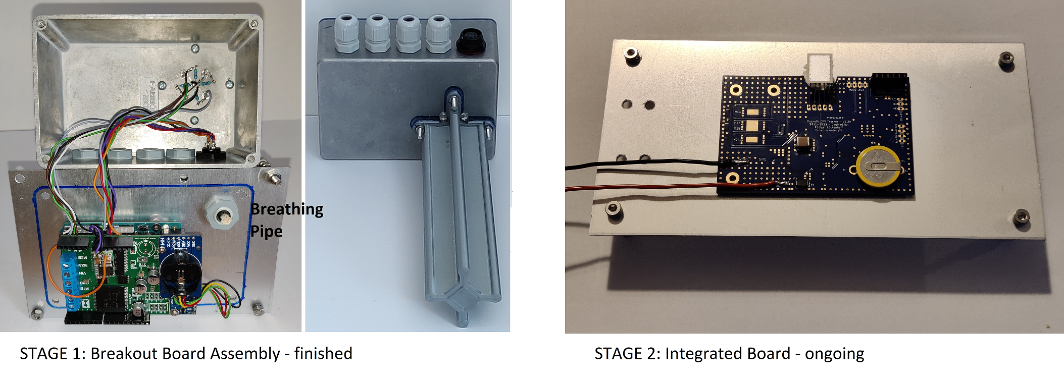
***STAGE 1: THE BREAKOUT BOARD ASSEMBLY***
A dual VNH5019 shield provides 6-24V, 0-12A motor control to an Arduino UNO. A real time clock and an MPU9250 compass chip are connected with only a few air wires. Everything together is stored in a sealed aluminum box with a tracking sensor on one side. Please see the linked video and the file 2021_08_14_Full_description.pdf for details.
***STAGE 2: THE MAGNETIC CPV TRACKER V2.0f BOARD***
The all in one control board follows the same principles as the breakout board assembly. Yet we had to replace the discontinued MPU9250 9-axis-compass and we chose chip level magnetic and acceleration sensors by MEMSIC instead. Furthermore, we replaced the costly VNH5019 motor drivers with an arrangement of 6 FETs and a DRV8300 gate driver.
In the present board design, we also included RS485 communication which will be required in a large tracker field where commands may come over a long distance from a central control cabinet. The board is not much bigger than a credit card and yet capable of controlling 8A at 12-36V. It is so flat that we can mold it in silicone on the backside of its mounting plate for encapsulation and thermal management. It is also designed to be EMC compliant.
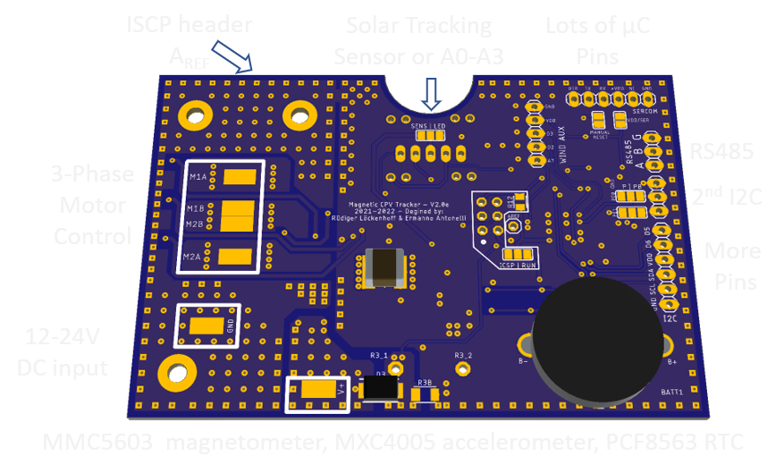
You will find the full CAD-CAM data together with the BOM and the ordering instructions in the file Magnetic_CPV_Tracker_v2_0f_Eagle_CAD_CAM_BOM_documentation.zip below (MIT license, Open Source).
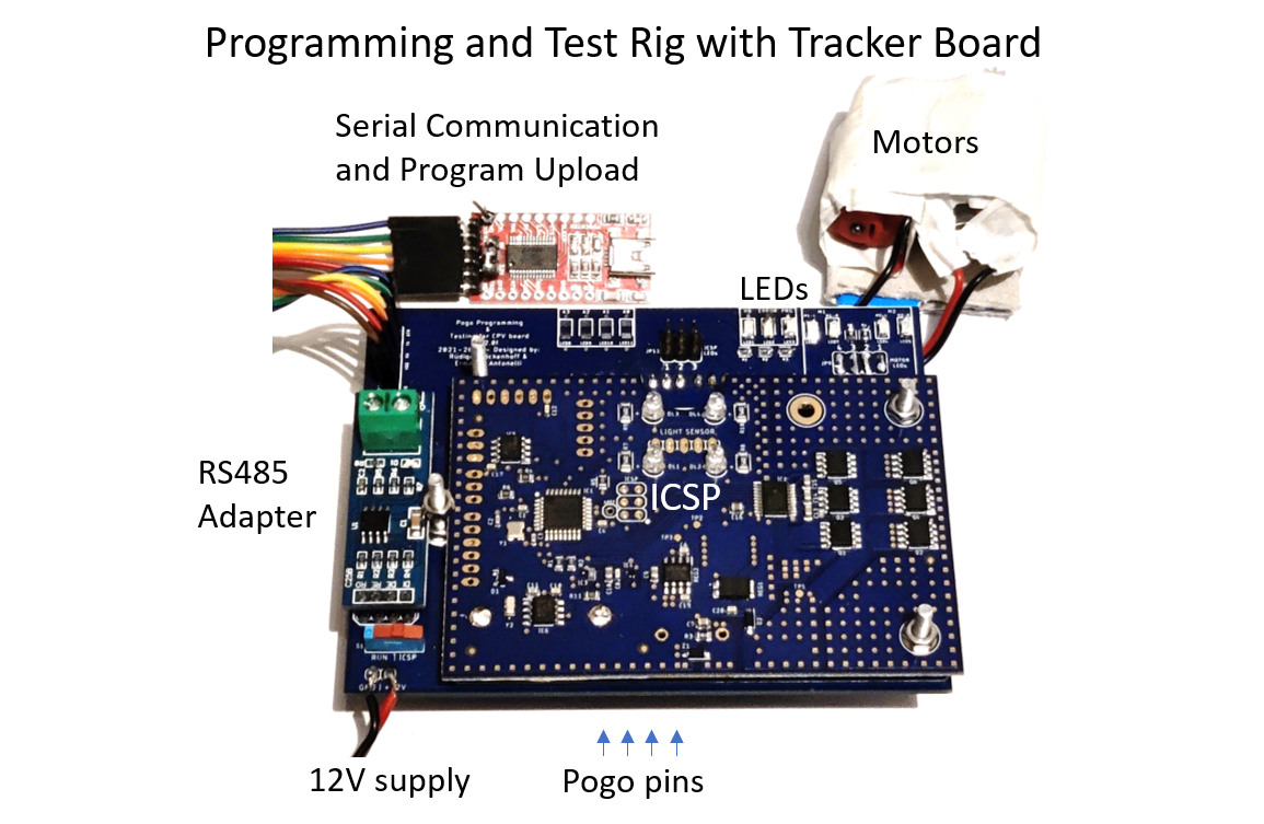
We have also built and tested a test rig for these boards and published the CAD CAM files https://cdn.hackaday.io/files/1851307920601920/Pogo_Board.zip. It consists of an Arduino Uno shield that contacts the board with pogo pins for ICSP upload of the bootloader and serial communication. An RS485 adapter will test the communication between the UNO and the onboard RS485 chip (yet to be implemented in the code). This programming and test rig is important because it is a prerequisite for an effective mass production of this board.
***THE CODE***
The code is written in Arduino and it is very similar for the V2.0f board and the breakout board assembly. It features a serial interface that lets you monitor the tracker operation, control the tracker and enter parameters into the EEPROM that define the tracker behavior and allow an adaptation to a wide range of tracker hardware. See https://cdn.hackaday.io/files/1851307920601920/2021_08_14_Full_description.pdf for details and https://cdn.hackaday.io/files/1851307920601920/221227_Code_for_V2_0f.zip for the full code (MIT license).
Presently we are only using 83% of the 31.5 kB program space of the ATMEGA328 so there is lots of space for advanced features like the RS485 communication scheme and motor current reporting for predictive maintenance. See https://hackaday.io/project/185130-open-concentrating-pv-solar-tracker-controller/log/211277-motor-control-and-current-measurements-work-very-well for details.
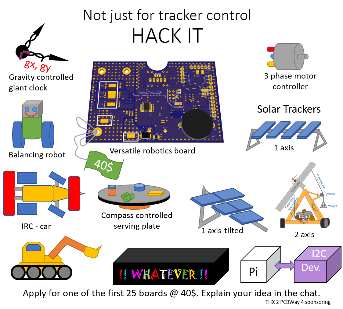
***ALTERNATE USES - GENERAL ROBOTICS***
Even so solar trackers are popular projects, this topic alone may not be enough to support a community around this board. We also want to make it available at an attractive price from several suppliers. It may and should be copied. So, we are also promoting this board as a general robotics board. It may control a balancing robot, a digger with chain drive and several servos, a remote automation in your garden controlled via RS485 and a lot of other stuff that we would never think of.
***POWERFULL I2C SLAVE***
By an adaptation of the tracker board firmware this controller may be turned into a powerful I2C slave device that receives commands from a computer and provides sensor data as needed. For instance, a RasPi may send motor speeds and servo positions via I2C and the board handles all the required PWM. Furthermore, the µC board constantly reads the sensors and RTC chips as well as analog input pins and stores the data in registers which are available via I2C. This frees capacities of the RasPi and allows it to focus on the more challenging computation tasks such as image processing and sensor fusion. Sometime we will provide a simple "I2C slave" sketch with the most basic functions but we certainly hope that a community kicks in at some point to hack this board for greater value and ease of use.
***THE TRACKER***
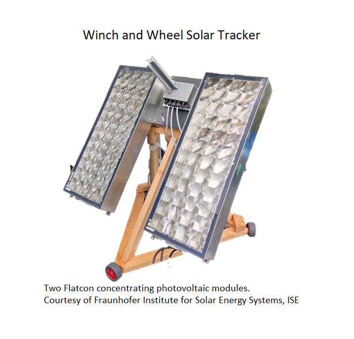
Even so this is an electronics project, it is made to allow new kinds of mechanics. Up until now people believe that precise trackers will require precise mechanics. This is not true! The mechanics only need to be able to perform small steps and be stiff enough not to swing in the wind. If they are “wobbling” while they move, it doesn’t matter if you are doing the fine adjustment using a highly sensitive sun sensor. This control is actually made for my favorite tracker design: a three wheeled carriage that turns on spot and pulls up the generator against gravity with a winch. If the ground is somewhat uneven that’s fine. It may even be gravel. The winch is not exact, but it is made in such a way that the rope slips when the storm is shaking the generator. Thus, the tracker will move to the safe “stow position” even without electrical power. I hope for more highly cost-efficient concepts that other people may come up with if they only have a control made to "track (almost) anything".
***SAFETY FEATURES***
I have seen a massive steel tracker structure bend like tin foil. The actuators are able to generate tons of force. So, you do need to think about safety.
Internal Sensors
The internal sensors don’t require external wires which are a major reason for failures.
Pull String Interrupter
Most trackers on pedestals don’t have a hard stop around the vertical axis (Azimuth). If there is a malfunction and they turn too far, they are twisting and ripping the wires which may have 1000V DC running through them. So, I made sure that the right wire will be ripped first, i.e. there is a string which is shorter than any of the wires and it will unplug a gold connector which supplies the motor current for the vertical axis.
Current Detection
The vertical axis will come to a hard stop and consequently the motor current will rise. Both versions of the tracker controller are able to detect this rise in motor current.
"Dead Man" Motor Control
The motor control is handled by an interrupt service routine in the background which will regard any movement as a step with soft start – plateau – soft stop. Even continuous movements are handled as such steps. The only difference is that the microcontroller resets the counter for the plateau in every main loop. If the main loop crashes, the plateau will end and the motor will stop within a second. This concept is well known from dead man switches in trains. If no one presses the button, the train stops.
The motor control circuit in the single board yet adds another layer of passive safety. It uses a bootstrap FET driver which only works when running at kHz PWM. Otherwise the charge pump runs empty and the upper FETs shut down the current. So even if the µC should stall with pins high or low, the motors will turn off almost immediately.
Wind Sensor, Go to Stow
There is a wind sensor port on the 6 pin SP13 connector. It can either be connected to a wind sensor that generates short circuit pulses (rotating magnet with a reed switch) or to another version which generates a voltage (DC generator). The firmware includes a go to stow - return from stow routine with EEPROM-parameter defined trigger levels for the wind speed.
Instead of an external wind sensor you could also use the accelerometer to detect a generator which is shaking in the wind. This is an option for future work. Feel free to join the project and test this idea.
*** MAKE IT A SUCCESS - BUILD UP A COMMUNITY***
We want to contribute to the energy transition. This project will only be relevant when it is applied in large scale.
One way would be to find a major company that decides to use this board for commercial solar trackers. I therefore presented earlier stages of this project at the Concentrating Photovoltaics Conferences CPV-17 (2021, Freiburg) and CPV-18 (2022, Myiazaki). Preprints of the papers are available on request.
I received quite a bit of interest but an assembly of breakout boards was probably not considered a feasible solution yet. We will therefore make another effort to promote the integrated board in the CPV community. We will also get in contact with manufacturers that provide single and dual axis solar trackers for silicon flat plate modules. And of course, we will approach the well-known suppliers of Arduino and RasPi compatible boards.
An especially valuable contact will be Frank Dimroth, Head of Department III-V Photovoltaics and Concentrator Technology, who considers using this board in a new project to design an integrated CPV system that will be pleasing to the eye for residential areas.
In parallel we want to build up a community around this board. People need to learn how easy it is to build a solar tracker around it and hackers should find versatile uses in the field of robotics. Once the integrated board is available and well documented, it will also be the first choice for solar trackers.
We ordered 25 boards to get this process started. They will be available at a discounted price of €40. This is your share of the cost after sponsoring through PCBWay.
A good rank in the 2022 hackaday prize contest may give us the required attention to get things moving.
***JOIN US – BECOME PART OF THE CLEAN ENERGY TRANSITION***
We need you! This is your chance to contribute to the clean energy transition. The small tracker in your backyard will serve as a valuable test site for this board. You might also come up with a novel concept that none of the major tracker manufacturers would have thought of and which may turn out to be the reference design for many solar trackers in the future.
Find cool applications of this board in the field of robotics. Solar trackers and robots will be complemental in an active community.
***GOODIES***
I learned a lot from other projects (THX a lot!). So, these are the features that I recommend for reuse (Github.com/solhunter):
04_Serial.ino: The serial interface that stores integer parameters in the EEPROM. They are addressable with ASCII signs and may be plotted as an 8x8 array together with the RTC time. Each output line of this array may be used as an input line for 8 parameters at a time. The upper and lower limits of each value are hard coded in the program. Other characters are reserved for commands. This interface only uses very little program space and is yet very powerful since it offers so many EEPROM positions without the necessity to address them separately. If you need to configure a control with many parameters in real time, this may be your solution.
05_ISR.ino: The soft-start, soft-stop motor control which runs in the background and writes pre-defined bytes to the digital ports that each represent a motor state. Needs an adaptation for general robotics where two motors should be running simultaneously.
09_astro.ino: The “good enough” astronomical tracking routine.
***LICENSE***
All stages of the project are published under the MIT license.
***ACKNOWLEDGEMENTS***
The code uses
SoftI2CMaster.h by Felias Fogg, GNU GENERAL PUBLIC LICENSE, Version 3, 29 June 2007
Arduino 1.8.7 including math.h and EEPROM.h