Close
0%
0%

Iteration 8

Science in your hand. A pocket-sized instrument capable of visualizing and exploring the world around you. (Iteration 8)

Similar projects worth following

It is my deep belief that knowledge brings about positive change.


We could live in a world where the same instrument that can show a child how much chlorophyll is in a leaf could also show how them much pollution is in the air around us, or given off by one's car. As an educator and a researcher, I feel that if people could easily discover things about their worlds that were also important social topics, that they would then make positive social choices, like reducing their emissions, or working towards cleaner industry in their communities.

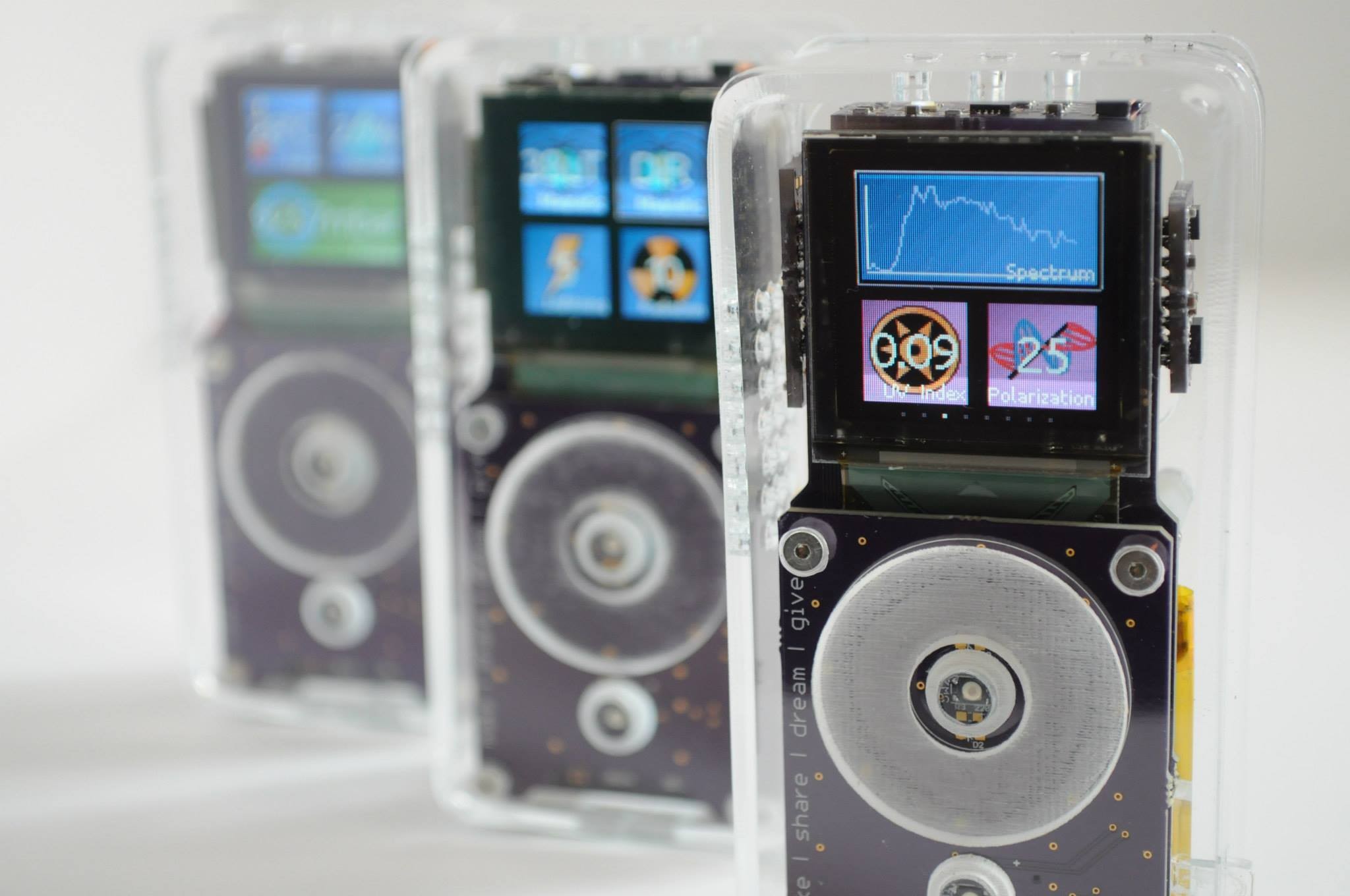
By having access to general inexpensive sensing tools, people can learn about healthy leaves, clean air, clouds and the water cycle, energy efficient homes — and visualize abstract concepts like spectra or magnetism.

As a tool for exploration, we can discover things around us that we don't already know. And that's what it's about. Little discoveries, everywhere.

  • Back at it with the Teensycorder

    peter jansen11/21/2022 at 06:39 6 comments

    Three years is perhaps a bit of a long while for an update, but here we go. 

    I've had precious little time over the past three years for my open hardware projects -- being a tenure track professor and a father to a little one already takes up most of my day, and when the pandemic hit it just took away every bit of time I had.  But, things are starting to get slightly back to normal, and I've been eager to finish off some projects including this latest iteration of the open source science tricorder project. 

    The world has of course also changed in the last three years -- in the electronics world, it's almost impossible to get ahold of some parts, including the Raspberry Pi Zero W's that Iteration 8 was originally designed with.  I have thought for a number of years of simply redesigning Iteration8 with a number of changes:

    • Microcontroller:  Use a microcontroller instead of a ]Raspberry Pi Zero W, as the Pi is very power hungry, and very hard to come by.
    • Screen: Instead of making the device a backpack for a phone, make it it's own stand-alond device like all the previous iterations. 
    • Sensor connectors: I really like the idea of connecting all of the sensors using connectors.  I'd like to do this but to the extreme -- connectors for everything, to make it easy to add to/modify. 

    I'm also intending on embracing the 80/20 rule: you can often get a project 80% of where you'd like it to be in about 20% of the time it would take to get it to 100%.  In my past open source science tricorders I've spent a lot of time keeping the board compact and saving every millimeter. Here I'd like to try and use off-the-shelf parts as much as possible, even if it makes the device a little bigger, in favor of finishing the project quickly. 

    Enter what I'm currently calling the Teensycorder until I come up with a proper name -- it's a handheld device with a speedy Teensy 4.1 microcontroller, a 2.8" LCD, and one of the blackberry keyboard breakouts from solder party.   One of my recent struggles with using a microcontroller has been the limited RAM.  For example, magnetic tile imager has an 8x8 grid of sensors (64 total) that are read as 16-bit values, that is capable of being read at up to 20,000 frames per second.  At 128 bytes per frame, that's 2.5 megabytes per second of data -- way more than is possible to store for most microcontrollers.  The Teensy 4.1 has 1MB of onboard RAM, with the ability to add 8MB of external SPI RAM -- so it should be able to fit this with room to spare. 

    I have drivers for the previous sensors from Iteration 8 currently working:

    • The 8x8 pixel magnetic imaging tile
    • The Radiation Watch Type 5 high-energy particle sensor with my external backpack to increase its sensitivity
    • The SCD30 CO2 sensor with a wide detection range (up to 10,000 ppm)
    • The SPS30 air particulate matter sensor
    • The TFMini Plus distance sensor 
    • MLX9040 low-resolution thermal camera

    The switch from a FLIR Lepton to an MLX90640 was a bit difficult because of the lower resolution, and one of the main benefits of the Pi is that it can easily connect to the Lepton through USB.  I've tinkered with Lepton drivers for the Teensy without luck, and can always hook up the Lepton through one of the SPI headers if I'm able to figure it out in the future. 

    Just like Iteration8, the sensor boards have small adapters that I put on the back to adapt their standard 0.1 inch headers to the small board-to-board cable connectors. 

    The motherboard for the Teensycorder essentially is a large collection of headers and connectors.  Currently, there are specialized headers for the radiation sensor, the magnetic tile (SPI), the TF Mini Pro (UART), two unused headers for the Hamamatsu spectrometer and an SPI camera module.  There are also plenty of standard QWIIC connectors for I2C devices, so that sensors with that interface can be added in...

    Read more »

  • It works! First data

    peter jansen09/22/2019 at 06:45 1 comment

    A quick update, with what is essentially the first data from Iteration 8!

    To say this project has been progressing slower than I'd hoped is an understatement.  Raising a little one and being on the tenure track takes up nearly every waking hour of each day, but I'm starting to be able to squeak in an hour after the little one goes to bed every now and again.  And with that -- substantial progress, finally!

    Thermal Images from the FLIR Lepton

    Above is a picture from the FLIR lepton, plugged into the GroupGets PureThermal2 USB breakout, interfaced to the Raspberry Pi Zero W.  I made use of disasterarchy's very helpful thermalZero example code to acquire frames of raw temperature data, and modified the example to pipe these out to stdout as a JSON string that any calling program can read.  I put together a very quick server using node.js on the backend, with some of the plotly node.js widgets to display data, and everything seems to be mostly working.  

    One of the issues with interfacing high-bandwidth sensors with a phone has always been how to get the data in.  While Android phones sometimes allow a physical connection piping data, this is fairly challenging to do with an iPhone.  Bluetooth initially seems like a viable alternative, but the bandwidth is also generally rather limited.  And even if either of those alternatives were viable, they would still require writing native Android or iPhone applications to read and display the sensor data, which would be a skill that I unfortunately don't have the time to learn.  The (proposed) solution with Iteration 8 has been to have the device take the form of a small web server mounted to the back of an arbitrary phone, so that the user has only to point their web browser to the device address, and they'll be able to interact with the sensing device using a standard web interface.  I am primarily a researcher and engineer, but I have had the opportunity to acquire somewhere between mediocre and barely-passable web programming skills over the past few years, so I think I have enough skill to make something that looks reasonably well (or, is at least functional) without having to invest a huge amount of time using this sort of sensing-device-as-a-web-server programming/interaction paradigm.

    The above screenshot is a capture from my phone (an iPhone 8), using a regular browser (safari), displaying a thermal image from the FLIR camera using the plotly heatmap widget. The framerate being captured by the device is about 10fps, but the web client is only updating about once every 2 seconds -- so much slower than the data is being captured.  I think this is a limitation in my knowledge about sending data streams -- right now I'm sending data in a non-streaming, regular get-request fashion, and sending it as JSON, all of which are likely slowing things down a great deal.  So this part is currently working as a proof-of-concept, but at a much slower framerate than is ideal.  Even still, that's a much better problem to have than having no data at all. 

    Magnetic Imager Tile

    By far one of the sensors I'm most excited about is my magnetic imaging tile, which is essentially a low spatial resolution (8x8 pixels), high temporal resolution magnetic field camera.  Though I've only run it at about 2000 frames per second, the DRV5053VA magnetometers used as pixels appear to have a theoretical maximum of about 20Khz, and I'm eager to try and run it at such high speeds and see what I can see.  While 2000 fps is enough to see the magnetic fields of transformers oscillating or fan motors spinning, I'm curious if 20Khz would allow one to image the coil of a speaker rendering audio frequencies, which would be very interesting (and cool) if possible. ...

    Read more »

  • A New Motherboard Design, now with more Pi

    peter jansen06/19/2019 at 07:58 0 comments

    A very quick update, with a new motherboard design.

    The concept with Iteration 8 is to have a science-tricorder-like device that fits on the back of a smartphone.  The central challenges have been figuring out how to interface high-bandwidth sensors (like the thermal camera and high-speed magnetic field camera tile) to phones that generally aren't able to easily have external input -- and more specifically, to do this with an iPhone like the one I carry around (it takes beautiful pictures, and has about 5,000 of my very loved 17-month old on it right now). The compounding difficulties are that being on the tenure track with a little one, I have essentially no time, and my first design for an Iteration 8 motherboard was completely off-base, being quite large, and having a number of design errors and oversights (as prototypes do).  It incorporated an Arduino Pro Mini for easily interfacing with the low-bandwith sensors, and a Raspberry Pi Zero for interfacing with the high-bandwidth sensors (and, communicating with the phone over WiFi) -- but it turned out pairing these two together with the Raspbery Pi programming the Arduino was very cumbersome, and the Pi Zero appears far too underpowered to run a responsive X-windows GUI, let alone develop the software for the Arduino on it.  The SD card on the Pi was corrupted from the unsafe powerdowns associated with a development environment enough to be very prohibitive to development.  But I think the general idea of connecting the two together is solid, so I decided to take another pass. 

    I decided I was overthinking the motherboard design -- trying to have all the features on it from the first pass, rather than having something simple that just worked, and progressively iterating new features with it.  Enter the new motherboard design above -- it includes:

    And that's pretty much it!  Intelligent power saving?  Not in this version, with the exception of a single manual switch on the USB connector to enable/disable the thermal camera (which can consume a lot of current).  Other than that, the whole thing basically consumes plenty of current all the time to keep it's ~2000mah battery warm.  But a lot of my mental effort has went to figuring out how to add enough power saving features to have this design powered for approximately 24 hours straight, which is rather challenging given the power requirements of the Pi Zero, so I decided to just continue on without power saving features in this iteration, and focus on getting something working end-to-end. 

    To keep the height profile small, the Pi Zero is soldered directly onto the motherboard.  The USB is connected using the same clever mechanism of the ZeroStem, which uses two castellated throughholes to solder directly onto the USB data test points on the bottom of the Pi Zero.  Simple, clever, and appears to work well so far!

    I've connected a number of sensors to the design so far, including the above two atmospheric sensors from Sensirion.  The SPS30 Particulate Matter Sensor (left) detects the distribution of particulate matter in the air, while the SCD30 CO2 Sensor optically measures atmospheric CO2 levels, while also measuring temperature and humidity.  I had included a VOC sensor, but I have questions about the accuracy of the measurements, so I'll set that aside for the moment.  Both sensors connect using I2C, which makes connection...

    Read more »

  • An atmospheric breakout, and radiation sensor backpack

    peter jansen09/01/2018 at 20:09 1 comment

    A quick update, with an atmospheric sensor board, and a quick-connect version of the radiation watch backpack. 

    One of the things my colleagues usually joke about is that I often say we need to "make our mistakes cheaply".  I say this to the students all the time, and it's a philosophy that one of my own mentors in grad school always used to impart upon us.  I thought I was pretty good at making my mistakes cheaply before parenthood, but now with a wonderful 7 month old, and almost no time for anything, I've been reevaluating my approaches to getting things done quickly with the constraint of having almost no time, to try and figure out new ways of still being productive on a vastly reduced time budget. 

    Enter the idea of small, independently-iterable modules, and tiny JST connectors with standard pinouts on everything.  Most of my hardware designs try to strike a balance between being monolithic and modular, but I really think flexibility and modularity will be the way to productively move forward. The idea here is building sensor modules that are small enough (from a design perspective) to be quick to design and test, with low-profile connectors that allow them to be placed in a small device, and easily replaced as they are iterated or improved.  If the shape of the ultimate device changes, it's likely not too big an issue, since the board-to-cable connectors allow much more design flexibility than the board-to-board connectors I've typically used in the past. 

    The above is an atmospheric sensing board based on the Sparkfun Environmental Combo Breakout that includes a CCS811 VOC sensor, a BME280 Temperature/Pressure/Humidity sensor, and the new and very wonderful Plantower A003 air particle sensor.   One of the really exciting features of the A003 is that it gives a histogram of air particle sizes, which (to a scientist like myself) is much more exciting than just a single number representing the PM1.0 or PM2.5: 

    Particles > 0.3um / 0.1L air:39
    Particles > 0.5um / 0.1L air:6
    Particles > 1.0um / 0.1L air:0
    Particles > 2.5um / 0.1L air:0
    Particles > 5.0um / 0.1L air:0
    Particles > 50 um / 0.1L air:0
    

    This particular board includes a cutout between the CCS811 and BME280 sensors, which helps reduce some of the difficulties with temperature measurement in this scenario -- the CCS811 is reported to warm up a fair amount, and this can throw off the readings of the BME280 if it's quite close.  

    Radiation Watch Type 5 Backpack

    The Radiation Watch Type 5 is one of my favorite sensors, being very sensitive, compact, and having very modest requirements to get it up and running quickly.  Usually when I use this sensor I add on an external comparator that allows one to tune the threshold of the output signal, and essentially increase the sensitivity of the sensor from the stock threshold of ~60KeV to something closer to the noise threshold of the circuit.  For the first iteration of the OpenCT scanner I used a 10-turn pot to tune this threshold.  For the Arducorder Mini, I used a static resistor, but found that it was perhaps sometimes tuned a little /too/ close to the noise floor, and on certain days would trigger almost constantly -- perhaps a function of temperature.  I've since iterated different versions of the detector circuit, including some intended to do spectroscopy through peak characterization (unsuccessfully).  Though I'd love to get that working one day, here, I settled on the simple version of the backpack, but with the pot/static resistor swapped out for a digital potentiometer, so that the threshold could be dynamically retuned at issue.  The not-too-mechanically-stable 0.1" header from the Arducorder Mini is also exchanged here with a low-profile 6-pin JST connector, for easy use and mounting. 

    Slowly but surely, progress is...

    Read more »

  • A Third, High-Speed Magnetic Imager Tile

    peter jansen02/12/2018 at 20:22 24 comments

    A quick update with a new high-speed version of the magnetic imaging tile!

    I've been very interested in visualizing things that are very difficult for us to normally see for a long while -- it absolutely fascinates me that there's so much around us that we just can't easily perceive, and I often wonder how much more we'd be able to understand about our worlds, and how much more interesting bits of science we'd be able to get done, if only we could easily see them as naturally as we see things like colour. 

    One of the most memorable examples of this, for me, is a little more than a decade ago when I'd literally just assembled my open source science tricorder mark 1, turned it on for the first time, and started wandering around the room to see what interesting things it might detect.  A moment later I'd stumbled upon a power adapter plugged into the wall with a transformer, and the oscillating field inside being detected by the magnetometer.  That magnetometer and visualization was updating at only a few cycles per second, much slower than the 60Hz oscillations inside the transformer, but it was enough for me to watch that aliased oscillating magnetic field vector make large swings back and forth, and make me wonder what it would look like if only we could see it hundreds of times faster, and with an image instead of just a single vector.  Magnetic field visualization also seemed much like low-lying fruit -- we've been very good at producing very low cost, accurate magnetic field sensors for a long time, so this seemed possible in the near term. 

    I can't say things happened as quickly as I'd hoped, or even that I was able to form an idea for what a magnetic imager might look like that evening.  But years later I ended up becoming fascinated with magnetic resonance imaging (MRI), and tried to dream up an idea of what an inexpensive desktop MRI might look like.  One of the difficulties with MRI is that it requires very homogeneous magnetic fields to be placed over a sample, in order to spatially resolve different parts of the sample (and render an image).  The normal way this is done is with a large, beautifully homogeneous, incredibly expensive superconducting magnet, but I had wanted to figure out a way to do it with a terrible, not super homogeneous, cheap electromagnet by reading all the field variations, and calibrating them out -- and I had decided to try to do this by creating a first magnetic imaging tile built out of a lot of 3-axis magnetometers in a 10mm grid.  That low-field MRI project stalled a bit (it turns out being a tenure-track professor takes a lot of your time), and along the way I was able to create a two much simpler (but incredibly slow, incredibly low resolution) desktop computed tomography (CT) scanners, but the idea of creating a magnetic imager for it's own sake (apart from the idea of building a low-field MRI) seemed very clear.  I put together an array of Hall Effect sensors that (unfortunately) lose the 3-axis vectors of many magnetometers, but have very fast updates, and built the Magnetic Imaging Tile V2.  That tile was very cool -- for the first time I had an imager with a reasonable spatial resolution (~4mm) and a large number of pixels (12x12, though I had only ever populated a smaller ~8x8 subsection).  But unfortunately my design choice of using an I2C I/O multiplexer for addressing each "pixel" (magnetometer) in the tile meant that it was limited to a framerate of about 10-30Hz.  This meant I could see very neat static fields live, but placing a transformer near the tile only showed it rapidly oscillating and unable to render a good image, because the tile was about a hundred times slower than it needed to be to sample such a fast field. 

    ... Read more »

  • A motherboard design, and figuring out where everything goes

    peter jansen08/28/2017 at 06:35 3 comments

    A very quick post with a very long picture -- but what I hope is a significant milestone after a year of collecting parts and breakouts.  After a few weeks of sketches and stacking boards atop each other, I think a design for placing the major sensing components on the back of a phone has emerged. 

    The central ideas behind this iteration, Iteration 8, are to

    • sit on the back of a phone, using the phone's display and communications capabilities, and 
    • to have a very low barrier to assembly, ideally requiring a shopping list of boards from major long-term vendors, and an afternoon with only modest (mostly through-hole) soldering skills.  

    I think I've largely been able to keep to these design goals, and put together a candidate motherboard design  (currently being fabricated) to serve as a test platform for this idea. 

    Though I didn't realize it until after I'd begun designing the motherboard, fundamentally the motherboard is simply an Arduino Pro Mini, a low-power off-the-shelf microcontroller for interfacing with sensors, connected to a Raspberry Pi Zero W, a high-power board capable of running a webserver (for the phone to interact with, to display data), communicating with the Arduino Pro Mini (for sensor data), while also itself interfacing with the high-bandwidth sensors: the FLIR Lepton thermal camera, the standard Raspberry Pi camera, the Hamamatsu microspectrometer, and the Magnetic Imaging Tile.  The rest of the board is largely universal 0.1" headers designed with enough room that it should be easy to connect whatever breakout boards the user would like to the system, with a recommended set supplied.   This makes the system very simple, expandable, low-cost, much quicker to put together, and ideally with a fair amount of longevity. 

    The expense of this simplicity is two-fold -- the first being size (the backpack will add at least 15mm of thickness to the phone, in addition to some area on the side of the phone for the Pi itself and an air particle sensor that will protrude towards the front (screen side) of the phone). The second is power budget -- the Pi consumes a lot of power, and my hope is to be able to keep it in a low-power state with the Arduino collecting and buffering data, then regularly wake it either to collect data from the Arduino (then sleep again), or wake for longer periods for user interaction, or to use the larger, higher-bandwidth sensors. 

    Hopefully in a few weeks when the boards arrive I'll be able to finally test these ideas, get a sense of whether this is a viable design, and begin putting together the prototype.

    Below is a quick sketch, to scale, with the major components depicted, as well as how they "stack up" in several layers on the back of an example phone: 


    thanks for reading (this admittedly very short post)!

  • A Magnetic Imager Tile

    peter jansen07/29/2017 at 21:52 10 comments

    A quick update with a new sensor I've been working on, a magnetic imager tile (something like a "magnetic camera").  It's definitely very cool to see magnetic fields live!


    Magnetic Imager Tile

    I've always been interested in visualizing things that are challenging to visualize, particularly those that are pervasively around us.  Magnetic fields certainly qualify for this -- I think it's absolutely fascinating that they're everywhere, but that we (generally) don't make more than point measurements of the fields, and only very rarely are images taken. 

    The most intuitive way to make an imager for something is to get a whole bunch of single sensors for that something, and place them in an array.  Alternatively, you can take a single sensor, and physically translate it through space, as in Ted Yapo's magnetic field scanner ( https://hackaday.io/project/11865-3d-magnetic-field-scanner ).  A few years ago I worked to build an imager by putting together an 8x8 array of the popular HMC5883L magnetometers, spaced about 1cm apart ( https://hackaday.io/project/5030-low-field-mri/log/15914-concept ).  This has plenty of positives -- each sensor is a 3-axis magnetometer, and the whole array could be read using a simple I2C interface.  Some of the difficulties are that such a large board with very tight-pitched components is a bit challenging to assemble -- I was only able to successfully assemble a 4x4 version, with the 8x8 (and it's 64 magnetometers) unfortunately only working as an object d'art.  One of the other challenges with the HMC5883 array was the packing density -- the number of external components meant the maximum density I could achieve were pixels (magnetometers) spaced 10mm (1cm) apart.

    It's been a few years since I had a go at this, and so I decided to put together another attempt: 

    • Simpler sensors: Large-pitch analog hall-effect sensors instead of I2C sensors. 
    • Higher density: a 4mm density using SOT-23 sensors requiring no external components
    • Addressable array: Analog addressing through a large array of analog multiplexers on the back of the board
    • Tileable: Able to create larger arrays by putting multiple boards adjacent to each other
    • Easy to solder: Only large pitched components, so it would be quick and easy to solder in a toaster reflow oven (for the array side) and with a hand iron (for the analog multiplexer side)
    • 12x12: The size of the array (12x12) makes it big enough to see interesting things, and small enough to (I hope) fit on the back of the eventual Iteration 8.

    I learned from my earlier attempt with the HMC5883L array that this would be a bit of a routing nightmare, and so I decided to try switching from EagleCAD to the open source KiCAD, to make use of it's push-and-shove router.  It took a bit of getting used to -- KiCAD still has significant usability issues, in my opinion -- but with some work the board artwork came together, with exactly enough room for everything.  The Hall Effect sensors and power traces are on the top side of the board, with the array of analog multiplexers to route the analog signals from the sensors placed on the bottom.   The bottom also contains an I2C I/O expander (U110) so that the array can be addressed using only 2 I2C pins instead of over a dozen address lines, as well as an external 14-bit SPI ADC (U111).  The raw analog signal is also broken out on the connector (J1), so that the board can be connected to an external ADC (like the internal ADC on an Arduino) very easily. 

    The board itself had very small 6 mil traces, which lead to some manufacturing issues.  I was able to cut around the bridged traces and wire-wrap fixes, and populated about half the array for testing:

    The bottom of the array, with the analog multiplexers:

    Frame Rate

    I ideally would like an imager with a high (~1000fps) framerate, to be able...

    Read more »

  • A first attempt at figuring out the MAX30105 Air Particle Sensor

    peter jansen03/27/2017 at 03:57 6 comments

    One of the areas of sensing that I don't have a lot of experience with is atmospheric sensing. While I've become familiar with sensors for temperature, pressure, and humidity, I am largely inexperienced with the array of sensors available for sensing various gasses or air quality metrics -- in large part because they've appeared too large or too power hungry for a handheld device, and/or generally having issues with accuracy. But clearly measuring air quality is an important social topic, and very useful for science education, and so it'd be great to be able to do this reliably in a small handheld instrument in one's pocket.

    I was excited last autumn to see Maxim release the MAX30105 Air Particle Sensor, an extremely small (~6x3x2mm) surface mount sensor listed as being able to detect air particles (they give the example of smoke detection on the product website). I was eager to see how this might work for detecting air particle measures like ambient dust level, or particle counts (e.g. PM2.5, a measure of how many particles are in the air that have a diameter of less than 2.5 microns), so I thought I'd run a few experiments.

    A quick first pass

    In order to see how well the MAX30105 compares with traditional air quality sensors, I ordered a few common air quality sensors (the DSM501A, above, and one of the popular Sharp line of sensors), and quickly cobbled together a MAX30105 breakout board to get a sense of what the data coming off the sensor looked like by eye. After about half an hour of recording in open air, I could easily notice changes in particle density from the DSM501A when (for example) opening up a window, but was not easily able to see these changes reflected in the MAX30105 data.

    The MAX30105 has 3 LED channels (red, IR, and green). Above are histograms of the counts coming off each channel. Before seeing this, I hypothesized that particle detection might appear as follows:

    • Hypothesis 1: A dust (or other particle) drifts by the sensor, partially reflecting some amount of light back towards the sensor, and shows as a (significant?) increase in the ADC count for one particular sample. Sampling over long periods of time then plotting a histogram, one would then expect to see a bimodal distribution -- a central bulge from returns where there was no reflection, then a smaller bulge of higher-intensity reflections, proportional to the dust sensity/properties of the air. (This is essentially how I understand the DSM501A functions -- using comparators to measure the number of counts over a certain threshold).
    • Hypothesis 2: The air generally reflects some very small proportion of light that one shines at it, proportional to the particle/dust density in the air. The general intensity of the reflection will correlate with the dust density in the air. (This is essentially how I understand the Sharp ambient dust sensor works).

    The above distributions look very close to unimodal Gaussian distributions -- so no extra overlapping distributions to support Hypothesis 1. The means also didn't seem to reflect Hypothesis 2, but I had very little data, and given the width of the distributions, any number of other issues could be at play -- noise from ambient light (though there is supposed to be some ambient rejection), improper mechanical placement, and many other issues.

    The MAX30105 datasheet is very light on details about the particle sensing application, so I e-mailed technical support with my data to see if any additional help or application notes were available. They were only able to say that the MAX30105 requires "very smart algorithms" to function, and that they were happy to sell those algorithms through a third-party distributor. It seems unusual to me to sell an air particle sensor without describing how it can be used for particle sensing, but hopefully with some work one can characterize what air particle sensing tasks it's useful for, and how well it performs at those tasks.

    A less quick second pass

    To help control for as...

    Read more »

  • From the Arducorder towards Iteration 8

    peter jansen11/24/2016 at 07:21 2 comments

    It's been two years since I developed the Arducorder Mini, and I have found myself brainstorming about what a next model would look like over the past few months. It feels like it's time to work on the next iteration of my open source, handheld, pocket-sized scientific instruments -- Iteration 8.

    Arducorder Mini: What went right

    The Arducorder Mini was a substantial undertaking, and turned out exceptionally well -- it's personally my favorite open sensing project, and I very much enjoyed the development process, and getting to see the final product. I'd like to briefly describe what went well with the project, and what could use improvement:

    • Diversity: The Arducorder contains nearly a dozen very different sensors.
    • Capability: Spectroscopy, radiation sensing, and thermal imaging have all been sensors on my wishlist for handheld sensing devices for quite some time. Here, these sensing modalities finally began to be incorporated. Other sensors, like the barometric pressure sensor, have so high a resolution that you can often measure someone's height simply using the difference in air pressure between their head and feet!
    • Connectivity: Ability to share many of the sensor readings wirelessly through Plotly.
    • Interface: A simple, visually attractive interface, that is very usable for core tasks.
    • Reuse: In the spirit of open source, many of the aspects of the Arducorder were individually reused for other projects. Most notably, the Arducorder serves as a reference design for the Hamamatsu microspectrometer, and the folks at GroupGets helped use this to bootstrap and enable a community of makers and engineers to order and use small quantities of these beautiful microspectrometers.

    Arducorder Mini: What could have used improvement

    Many aspects of the project worked very well. As with all experiments, there was room for improvement:

    • Usefulness: The Arducorder Mini is has the most diverse array of sensors of any portable electronic device that I'm aware of. One of the most common questions I get asked is, "What can I use it for?". Individually, there are many applications for each of the sensors apart from science education -- for example, thermal imaging can be used to find heat leaks in your home, or for various tasks in industrial settings. Radiation sensing is something that likely isn't a part of everyday life for most folks, but the Arducorder Mini's radiation energy histogram showed an unusually high concentration of very high energy particles while sitting on my desk one afternoon when there happened to be a solar flare -- likely my first handheld solar flare measurement! Does this mean we can create crowd-sourced cosmic ray observatories with some large number of handheld instruments such as these? Similarly, the visible light spectrometer is an extremely powerful instrument, but needs much more work on specific applications, and industrial design supporting specific kinds of common measurements -- for example, allowing absorptive measurements through small sample vials. The list goes on. All together, the device is quite capable, but identifying and then developing specific use scenarios will help increase it's usefulness.
    • Industrial Design: It is extremely challenging to meet the mechanical and industrial design requirements for a dozen different sensors. Some of the readings (for example, from the atmospheric temperature sensor) are not accurate, because the unit heats up quite a bit from the battery and processor. Gaskets are missing on atmospheric sensors. As above, sample container adapters and/or other mechanisms for absorptive measurement need to be incorporated to increase the utility of the sensors in common use cases.
    • Ruggedness: The design is pretty solid, but not solid enough that I feel comfortable carrying it around everyday in my pocket without fear that I'll break it after a week or two of constant use. When I ship it to folks to use in demonstrations, it sometimes comes back with some of the sensor boards unconnected...
    Read more »

View all 9 project logs

Enjoy this project?

Share

Discussions

josh034 wrote 10/13/2023 at 02:27 point

Have there been any updates? Has anyone had success with building one? If so, how did it go?

  Are you sure? yes | no

aaaaaa wrote 05/26/2023 at 16:55 point

great project

I looking for communicator and terminal ssh, gcc, git etc. What You think about add step up -down from 0.5-24.5V

emergency input power: AA, lipo, 18650, car battery etc ;)

  Are you sure? yes | no

Similar Projects

Does this project spark your interest?

Become a member to follow this project and never miss any updates