Mild Lee Interested
Why am I doing this?
Wine is best stored at a stable temperature in the mid to high teens (Celsius). This is difficult to achieve when you live in a location where the temperature regularly exceeds 45 degrees in summer. Even a year stored in such conditions permanently changes the character of wine – almost always for the worse.
Fancy climate controlled wine storage cabinets are readily available, however these are expensive, inefficient and almost always prioritise aesthetics over function. I don’t want to look at my wine or show people how great I am. I just want to be able to drink it.
My priorities or storage are:
- Good storage capacity
- Reasonable price to buy / build
- Efficient to run
- Reasonable protection from damage in the event of system failure
Aesthetics is
irrelevant – it will live in a shed.
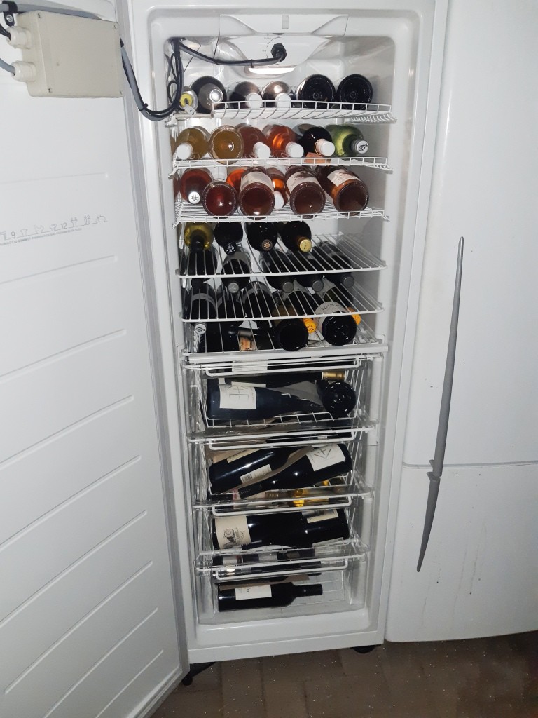
I believe that an upright freezer is probably the best option for conversion. It is preferable to a fridge because the insulation is thicker and thus it will take less energy to run. A chest freezer would also work, but it would be more difficult to access the contents.
Components
1.) The freezer.
For ease of conversion, I deliberately looked for a freezer with a mechanical thermostat. Conversion of a freezer with an electronic temperature control system should be possible, but replacing a simple mechanical thermostat is the simplest possible circuit.
The freezer I purchased on Gumtree was an Electrolux model EFM3001WA-X 300 litre upright, manufactured approximately 2013. It was in good condition with some minor cosmetic damage on the exterior.
Cost: AU$150
2.) Temperature Controller.
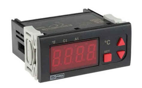
To replace the factory thermostat, I used a modular, programmable HVAC controller. These handy units combine logic, control relays, alarm relays and a temperature display in one easily installed module at a relatively low cost. Temperature is sensed using an external NTC temperature probe. I used a cheap RS Components “RS Pro” branded unit: model number 124-1056.
Cost: AU$140 each. For reasons explained below, I purchased 2 of these.
https://au.rs-online.com/web/p/temperature-controllers/1241056
3.) Temperature Probe
Suitable waterproof NTC thermistor probes with 2m cables were purchased.
I can’t remember exactly which ones I selected, but these are representative.
Cost :AU$10 each
https://au.rs-online.com/web/p/thermistors/1879306
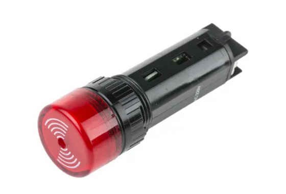
4.) Alarm buzzer / light
An alarm light and buzzer was also required. The 240V one I selected requires a 19mm cut out.
Cost: AU$24
https://au.rs-online.com/web/p/electronic-sounders/8772015
Also required were an adaptable box, electrical cabling, cable glands and a couple of single pole relays and relay holders.
Total cost of these miscellaneous items would be less than AU$100
Modifications
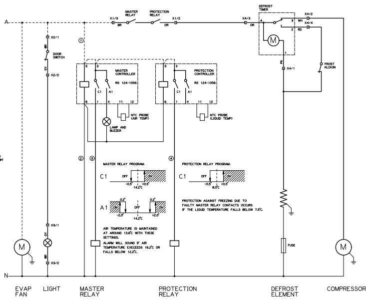
The original freezer circuit was essentially the same as this standard one:
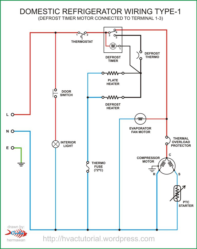
Only two changes to this control wiring were required:
- Replacement of the mechanical thermostat with the programmable HVAC controller.
- Rewire of the internal fan (evaporator fan) to run continuously instead of only when the compressor is running.
1.) Thermostat replacement.
The simple design of this freezer had the thermostat, defrost circuit, light and door switch circuits all housed in a single moulded housing at the top of the compartment, making it nearly ideal for modification.
Connection to
the supply, compressor, defrost element and internal fan (evaporator fan) are by 4 x modular plugs built into the main fridge body, making it relatively
easy to remove the entire control compartment to do the work.
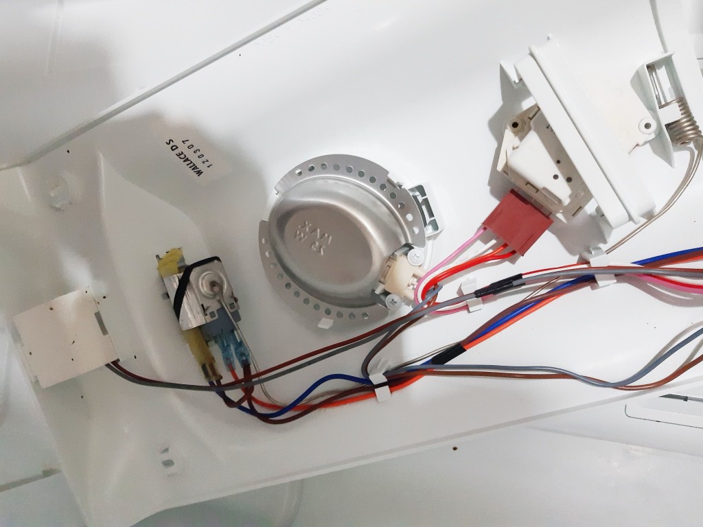
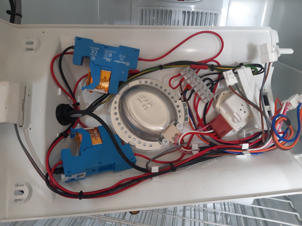
The final design uses 2 x interposing relays for control of the compressor and these were easily accommodated in this control compartment, along with a “chocky block” connector for making the connections to the original control loom.
The interposing relays take the place of the old mechanical thermostat and are in turn controlled by the new HVAC controllers.
Each programmable HVAC controller has 2 outputs.
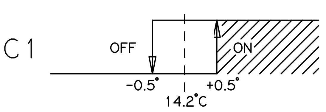
The “Master Controller” control output C1 is configured to switch the compressor on when the interior AIR temperature of the freezer goes above 14.7 degrees C and switch it off when it falls below 13.7 degrees C, resulting in a mean liquid temperature of around 14 degrees.
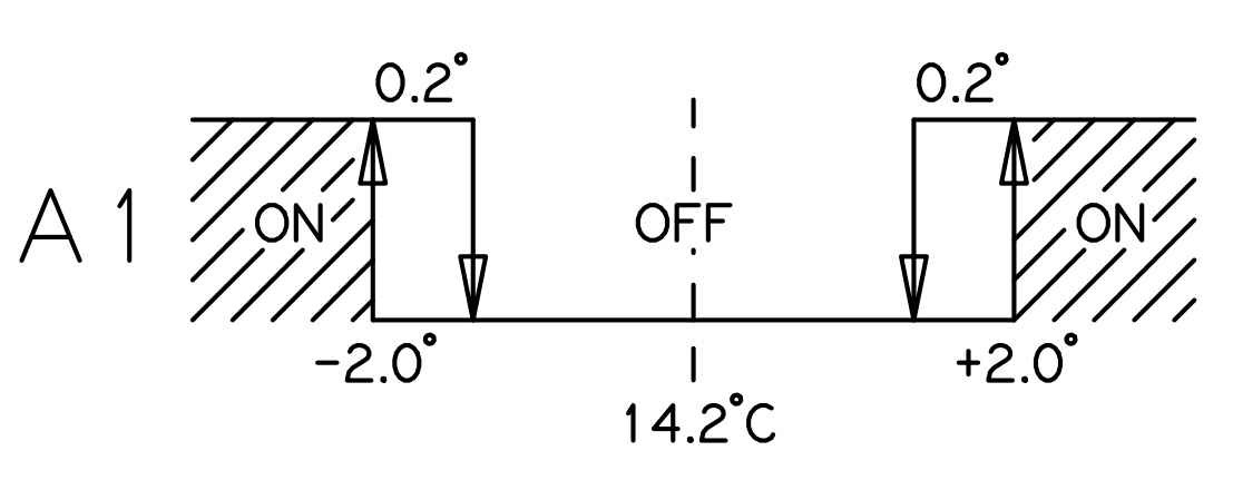
The alarm output A1 is configured to switch on an alarm buzzer/lamp if the interior AIR temperature is more than 2 degrees above or below the set point. This is sufficient to provide warning of a door left open or if a fault causes the compressor to run on too long.
The interposing relays are used in order to ensure the longevity of the controller. These cheap, easy to replace components are used rather than the controller internal relays to switch the compressor load.
There is a small risk of worn relay contacts welding in the closed position. This would result in the compressor running continuously and lowering the temperature below zero (it’s a freezer after all) resulting in broken bottles and the destruction of the entire collection.
To guard against this, an additional “Protection Controller” is used to monitor the LIQUID temperature and shut down the compressor if the LIQUID temperature falls below 8 degrees C.
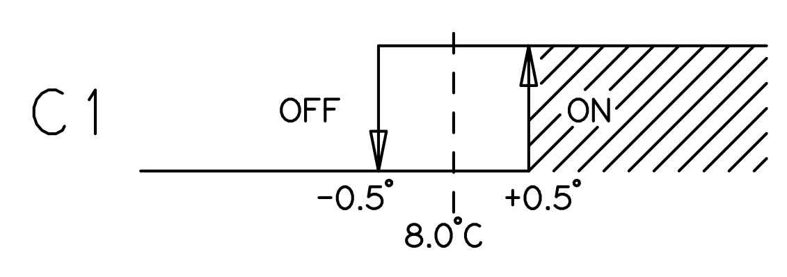
The final circuit
simply replaces the original mechanical thermostat with the contacts of these two
relays in series. A .pdf copy of this circuit is included in the downloadable resources attached this project.
The HVAC controllers were mounted into the freezer door. The thermal insulation was removed to make room and the bare metal of the door and the cut edge of the remaining insulation was isolated from the electrical components using 2mm thermoplastic sheet and silicone. An appropriately sized protective earth was installed to make safe the metal door in the event of an electrical fault.
This work was completed from the inside face of the door and a plastic adaptable box was then installed over the cut out to provide access for repair, an ingress point for cables and housing for replacement foam insulation behind the new controllers.
The electrical connection between the new controllers and the original control housing was made using a suitable 1.5mm^2 4 core + earth double insulated flexible cable. This is run through a cable gland in the new control box and another one through the enlarged hole left by removal of the mechanical thermostat.
A second cable gland provides a path for the NTC temperature probe cables.
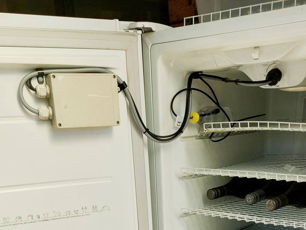
The “Master Controller” temperature probe is run through the original control housing and located in the air flow duct at the back of the freezer compartment, ensuring that the reading it provides is representative of the true freezer cabinet air temperature.
The “Protection Controller” temperature probe is installed inside a small bottle of water in the main freezer cabinet, providing a true reading of the liquid temperature of the wine being stored.
2.) Evaporator fan re-wiring
The interior fan (“evaporator fan”) is used to circulate chilled air from the evaporator coils at the bottom of the freezer cabinet through the freezer interior. In the original design of the freezer, this fan runs only when the compressor is operational. This works well to limit the heating effect of the running motor while ensuring that the chilled air is well distributed.
My preference is to avoid the risk of a temperature gradient from top to bottom of the cabinet due by running the fan continuously.
This was electrically very simple to achieve, but required installation of a new 1.0mm^2 2 core + earth double insulated cable from the top control housing down to the fan via the air circulation panel at the back interior of the freezer cabinet.
Results
This cellar has been in use for about a year and has proved to be very stable, as can be seen from this 3 month log.
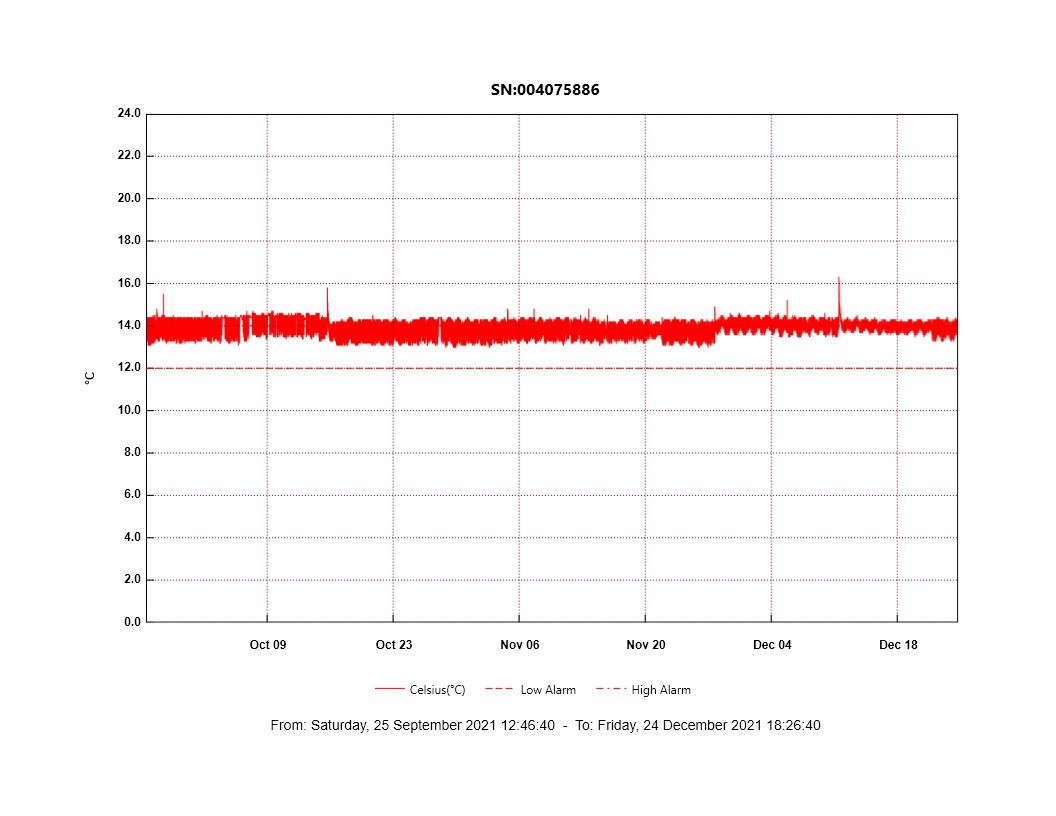
Happy drinking!