Open Green Energy
I have designed this lamp by inspired from Moser bottle which was invented by Brazilian mechanic Alfredo Moser. The concept is that clear plastic beverage bottles filled with water and bleach can be fixed into the roof of an unlit building to refract sunlight around a room.
In 2011, Illac Diaz used Moser’s technology to start the Liter Of Light ( MyShelter Foundation), which used a grassroots model to provide lighting on a large scale. The program uses partners around the world to keep costs down, using recycled plastic bottles and locally sourced materials. The program also promotes local entrepreneurs, by providing financial incentives to locals who assemble and install the lights.
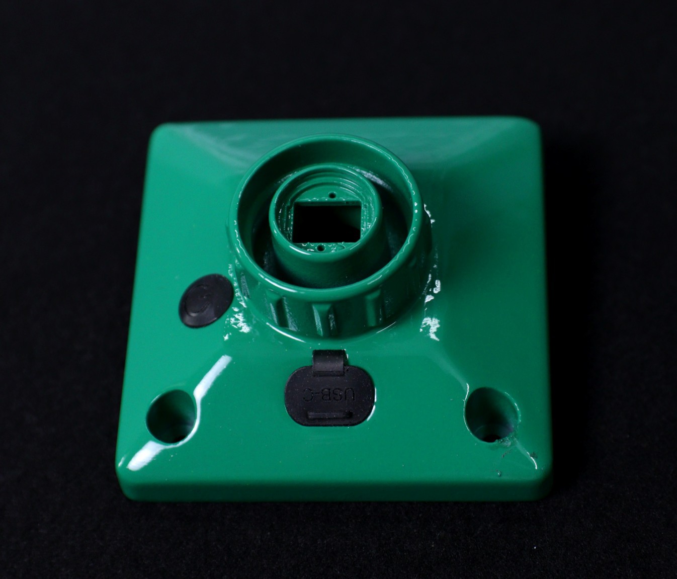
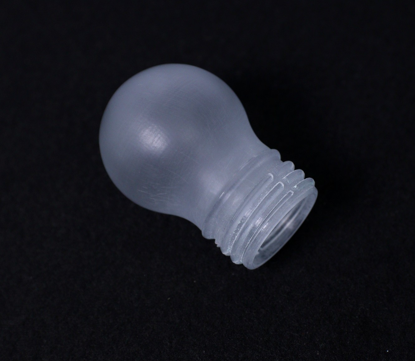
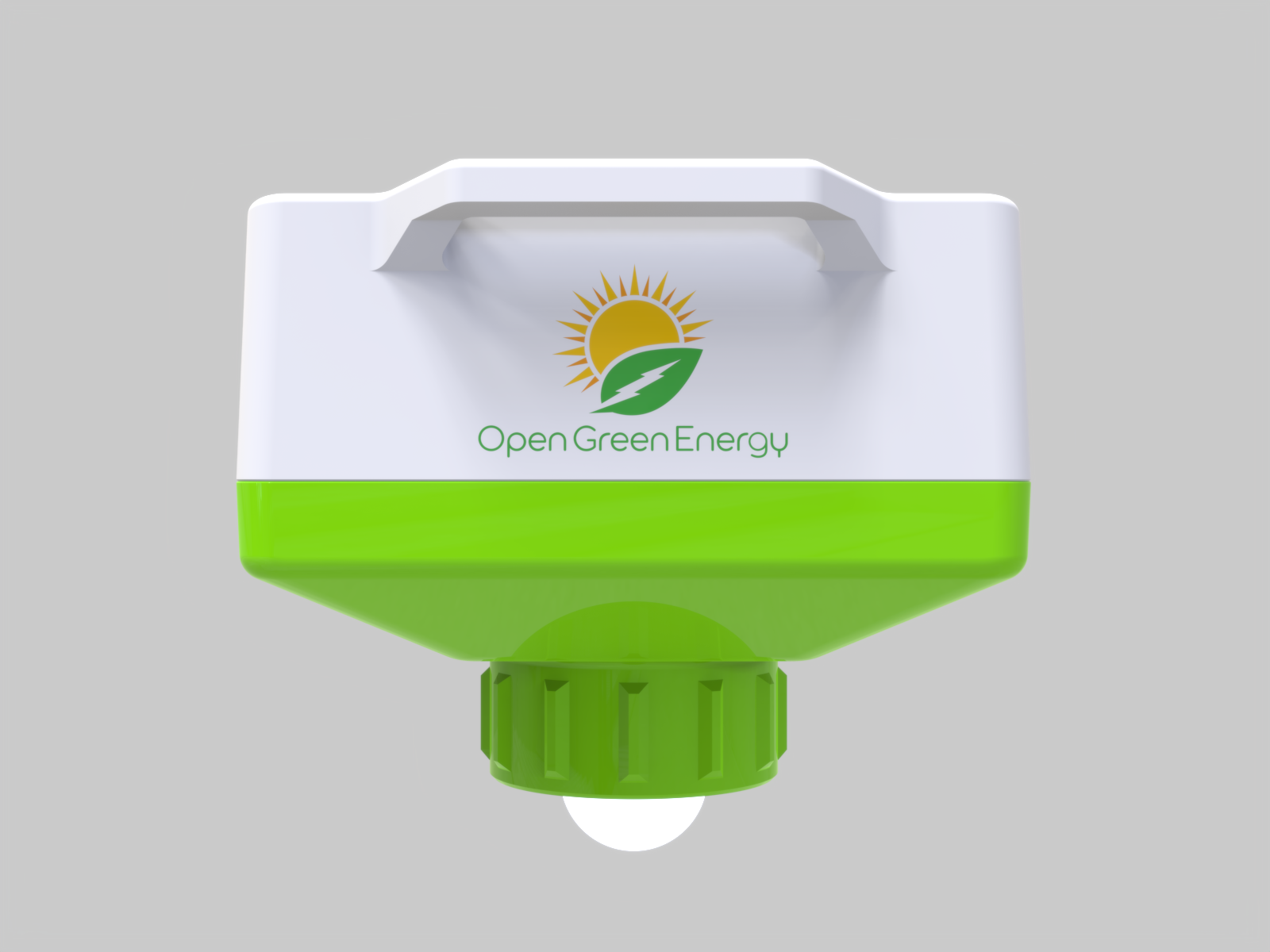
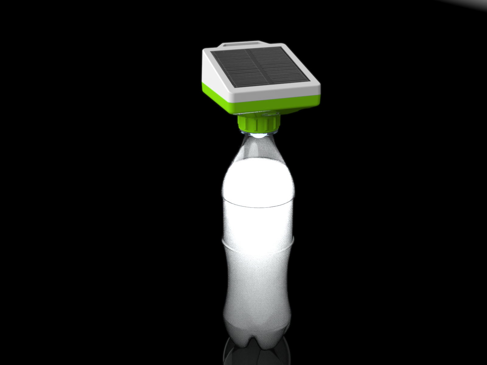
The Moser bottle lamp is simple and inexpensive but has a limitation. It only works during the daytime. So I have designed a solar bottle cap that can provide light during the night. By combining the Moser Bottle concept and my Solar Bottle Cap, a powerful lamp can be made.
Benefits:
- Reusing plastic bottles can significantly reduce pollution, greenhouse gas emissions, and energy usage.
- The use of the solar lamp will decrease the amount of local air pollution and saves energy.
- It can provide access to solar lamps at an affordable price to a wide range of people living in remote villages that are deprived of clean energy access.
- It also came out as an alternative business model with the potential to strengthen the overall rural economy by generating technology-based livelihood opportunities.
Working of Moser Bottle:
It works by the refraction of light rays because of different mediums, air, and water. By refracting light from the sun, it produces light 360 degrees around the room with an equivalent light power of 55 watts bulb. It will last for 5 years without maintenance and before the water has to be changed. The chlorine prevents the growth of microorganisms and maintains the clarity of the water.
If you want to know more about it, you may go through a nice research Journal. It is attached in the files section.
Image credit: - believe.earth
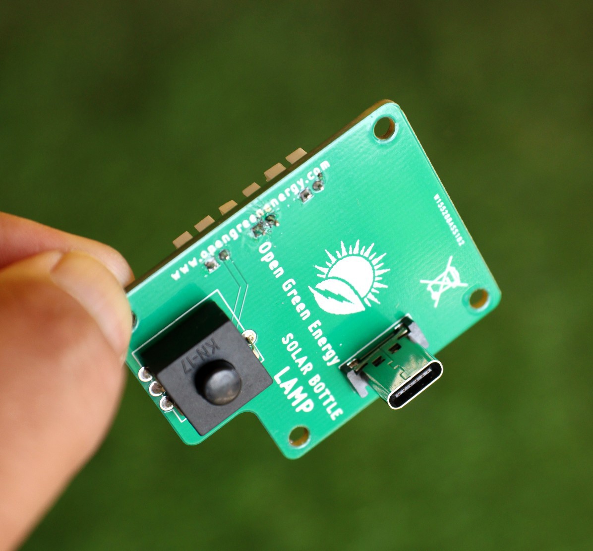
How the Solar Lamp Works:
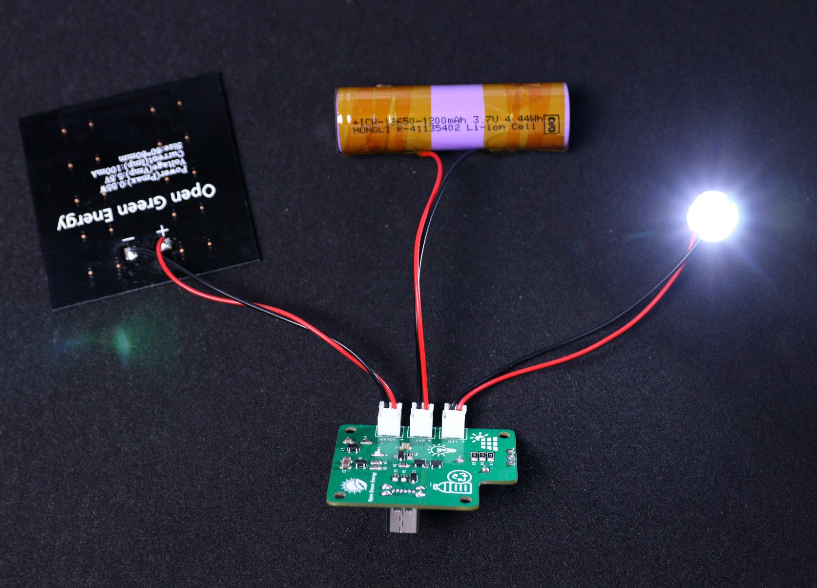
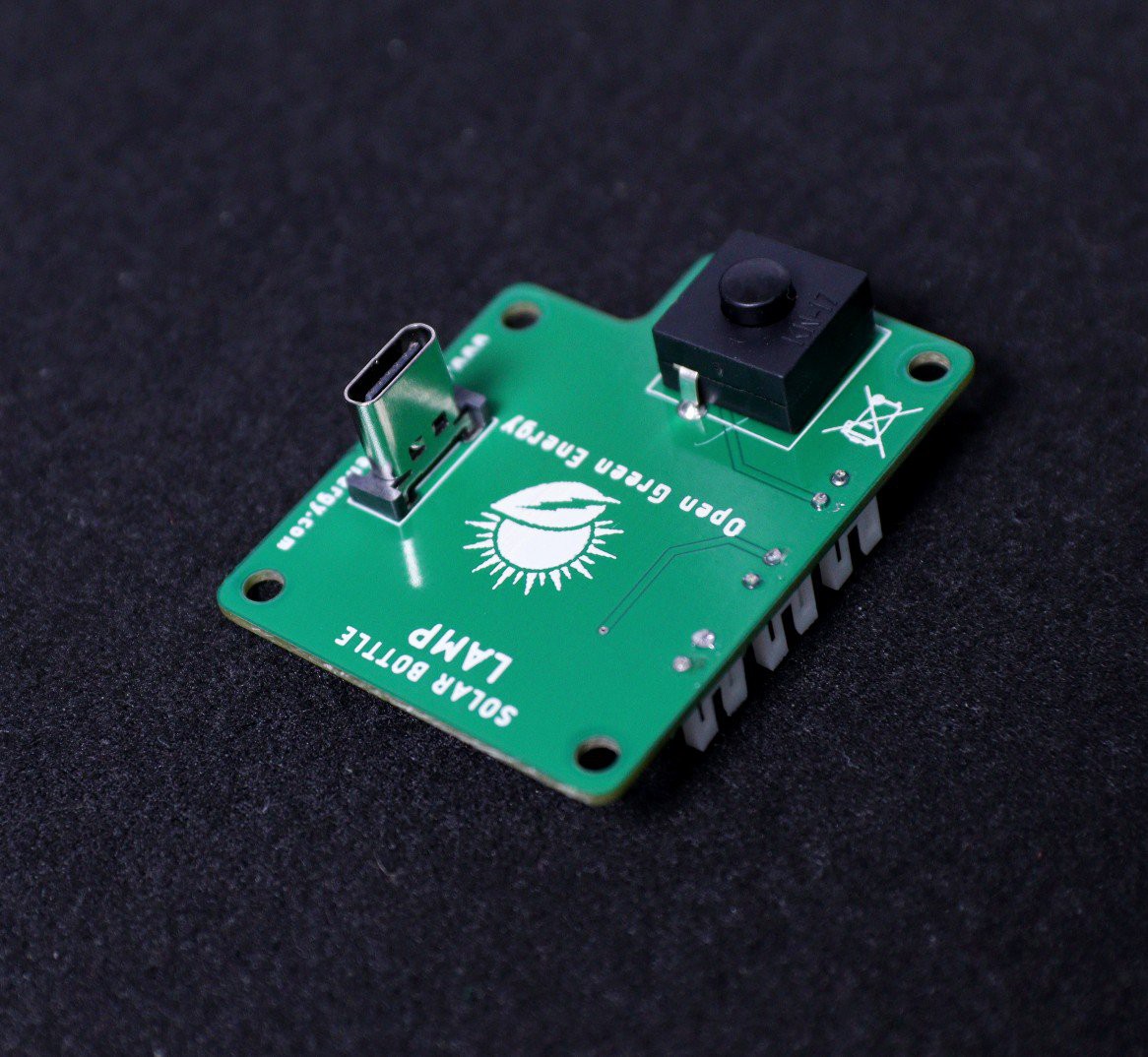
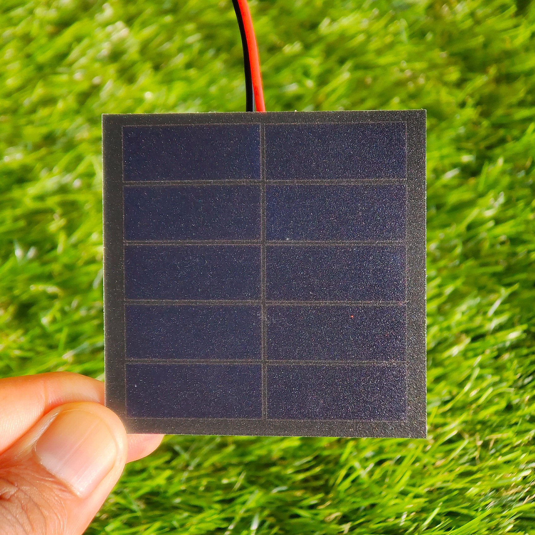
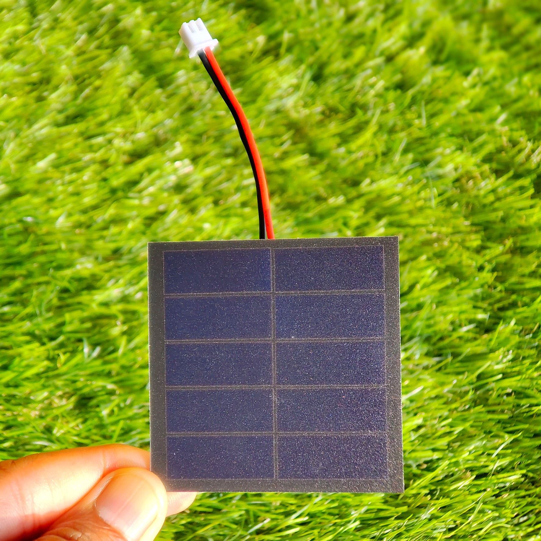
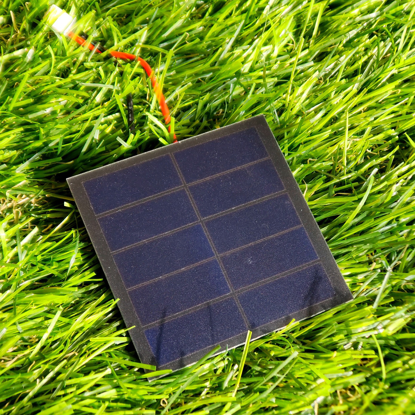
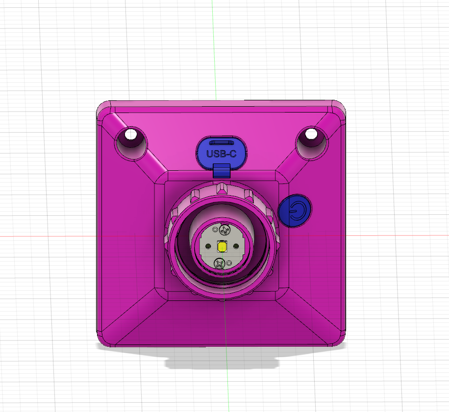
The solar panel receives sunlight from the sun and converts it into electrical energy. The controller board charges the battery during the daytime and drives the LED during the nighttime.
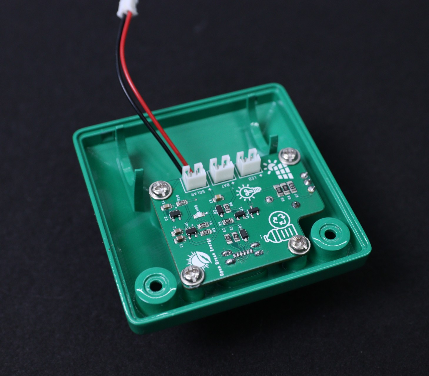
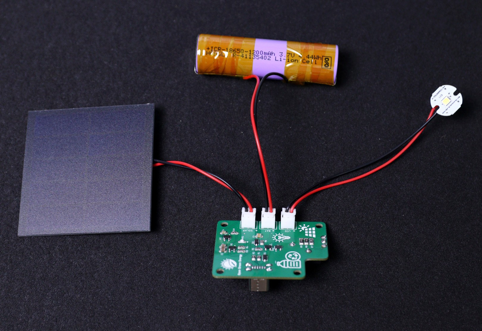
The solar lamp can be considered as a standalone Solar Photo Voltaic (SPV) system and contains four basic components:
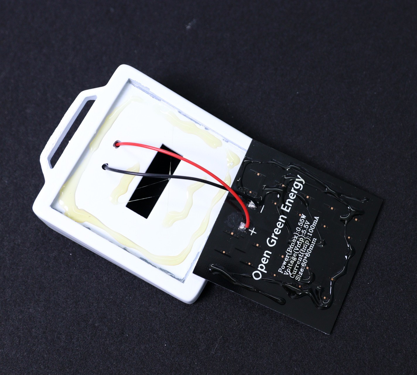
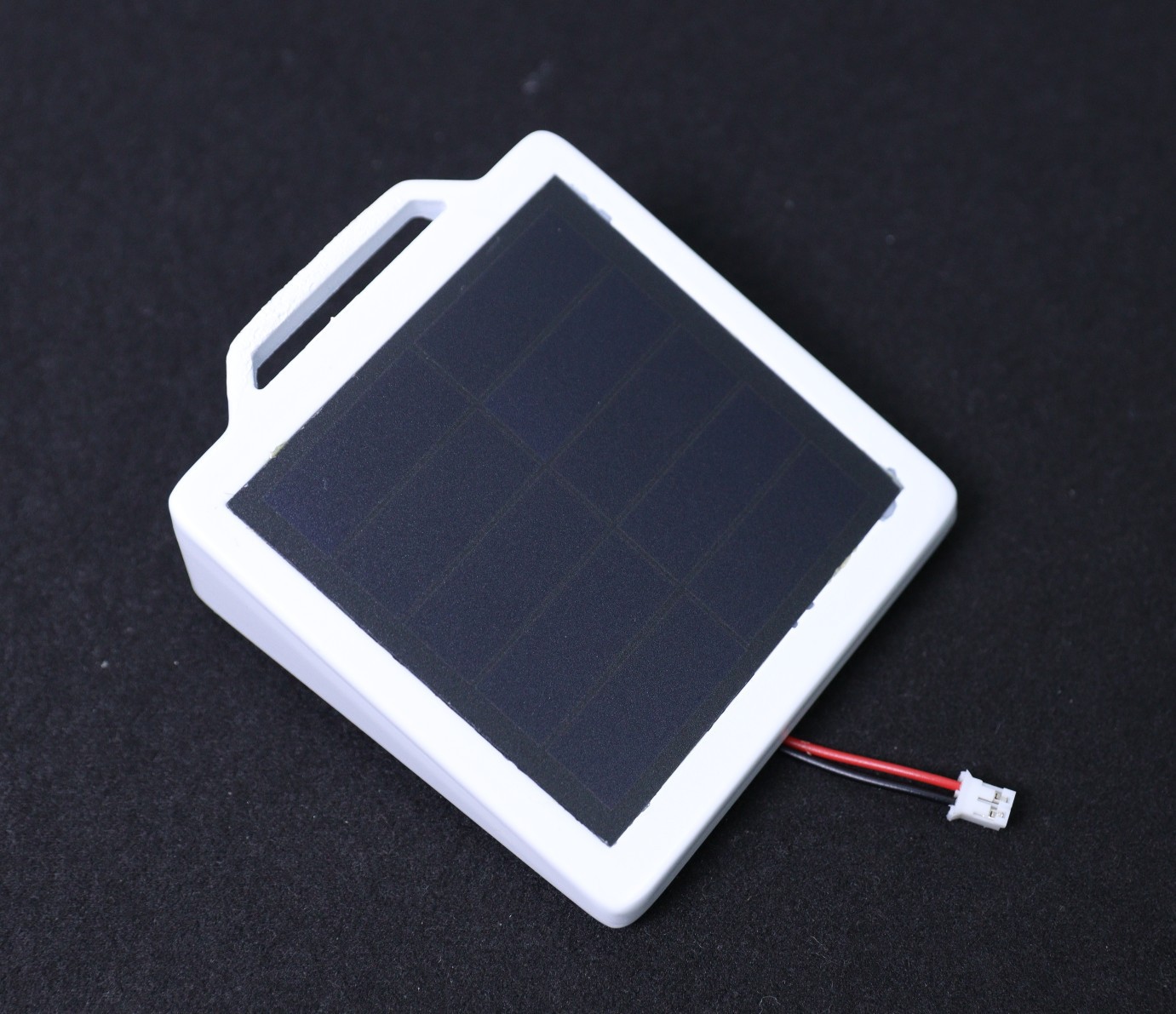
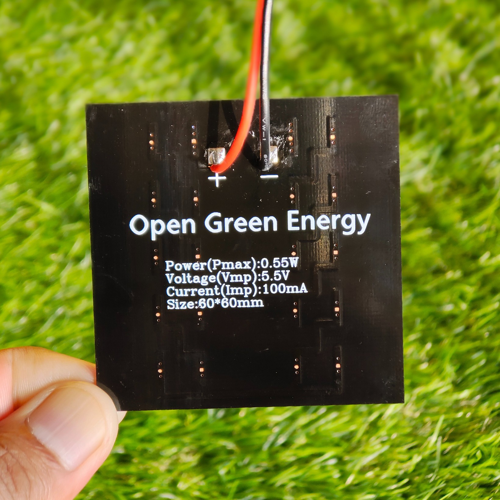
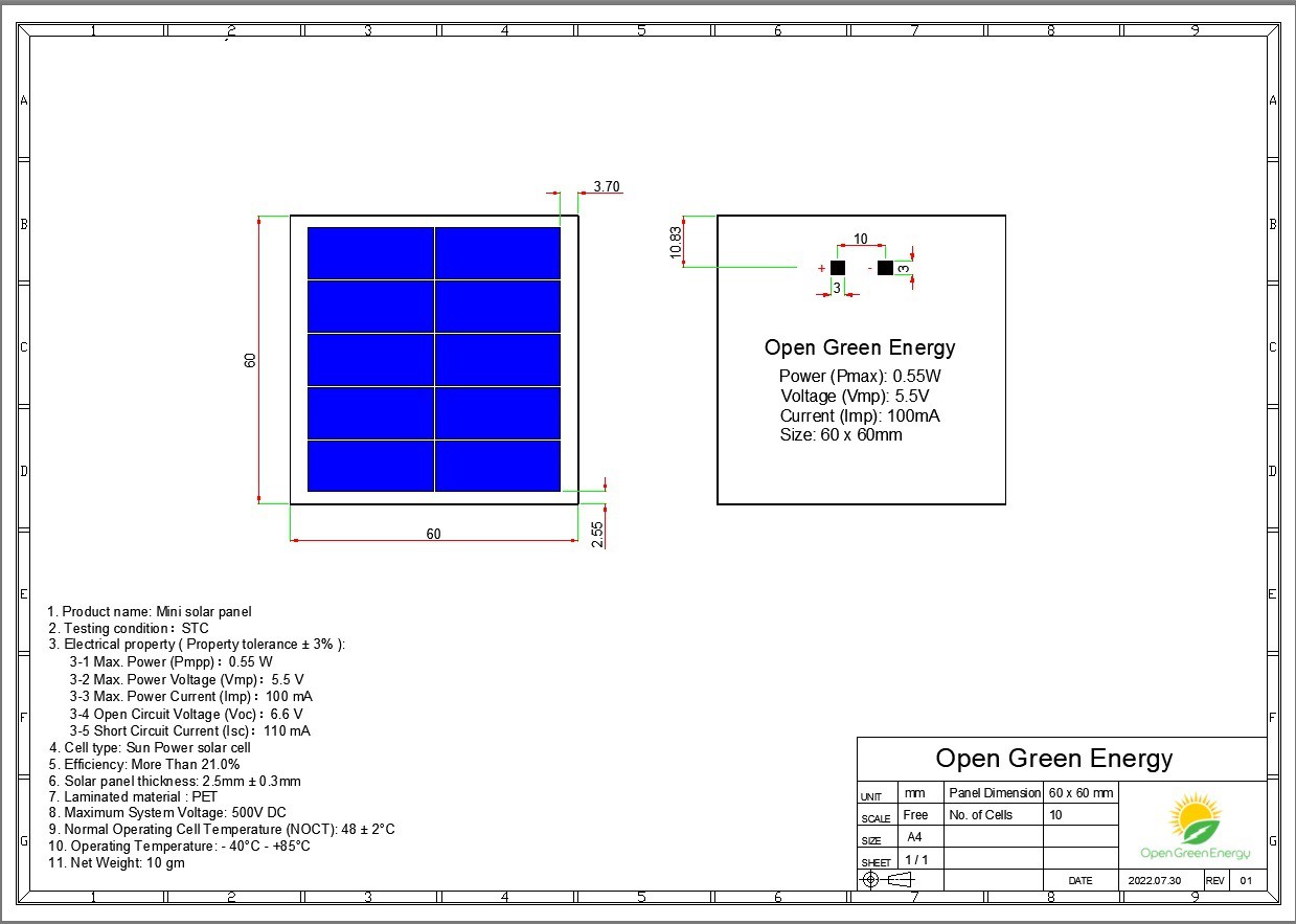
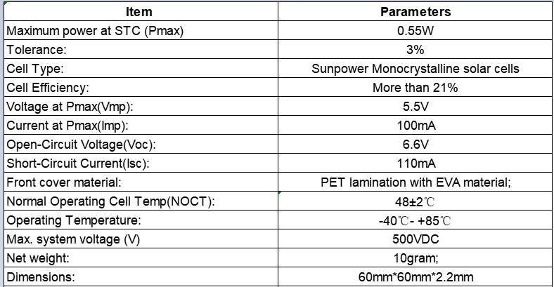
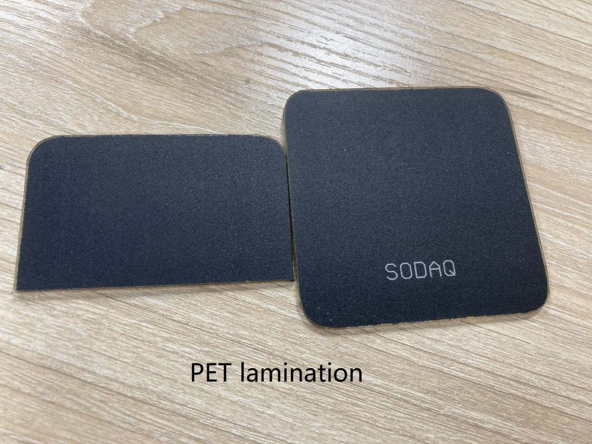
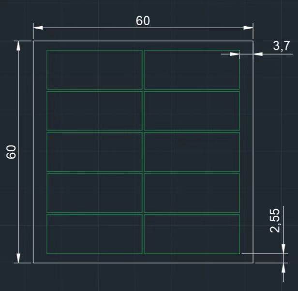
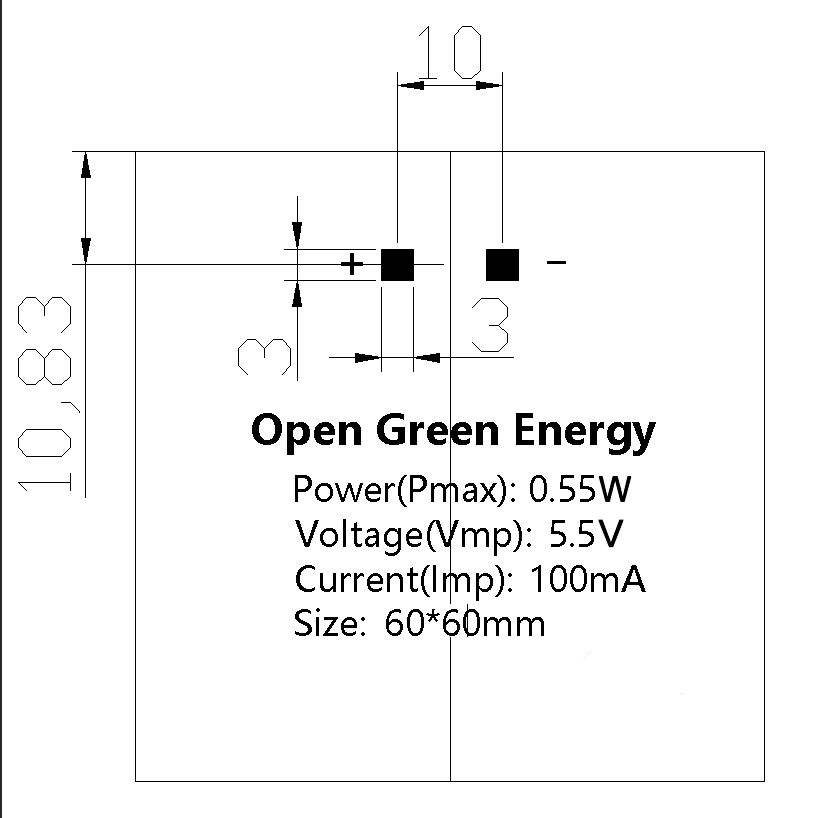
1. Solar Panel: Convert Solar Energy to Electrical Energy
2. Controller: Charge the Battery ( Charger ) and drive the Load ( Driver )
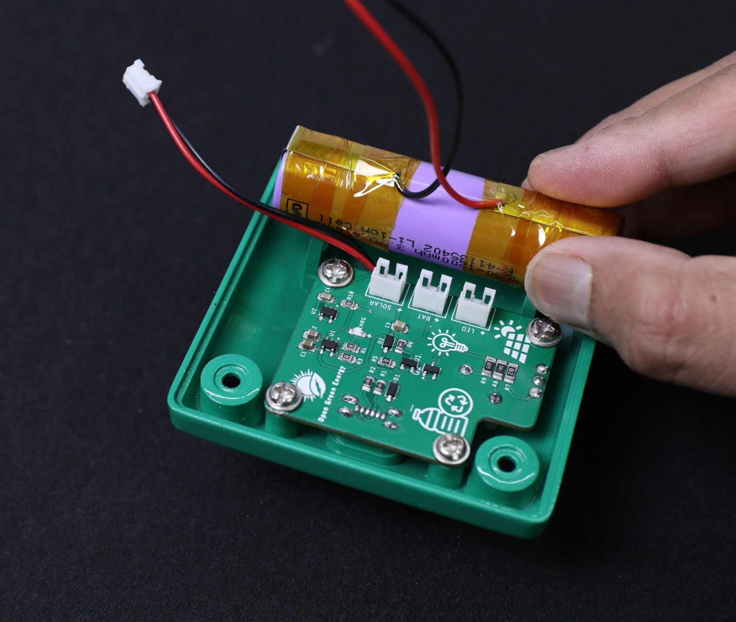
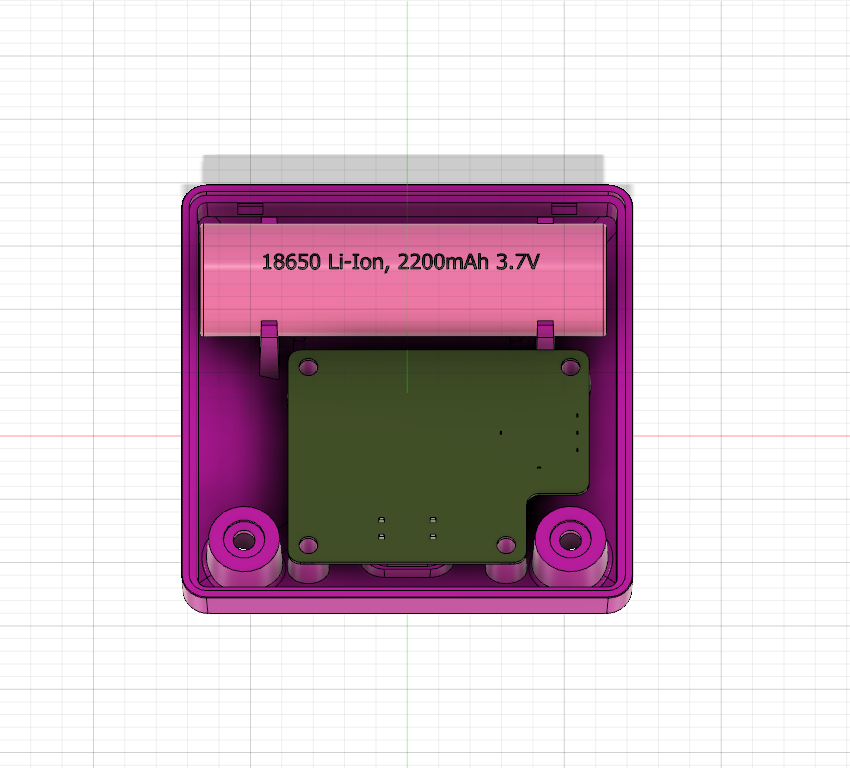
3. Battery: Store the Electrical Energy
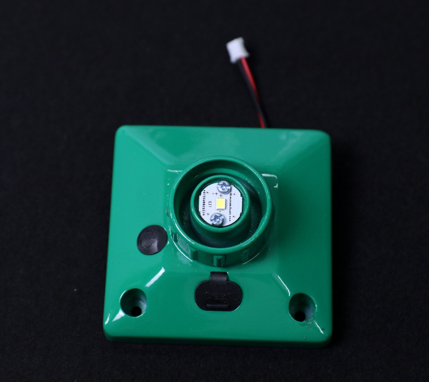
4. Load (LED): Provide the desired light output
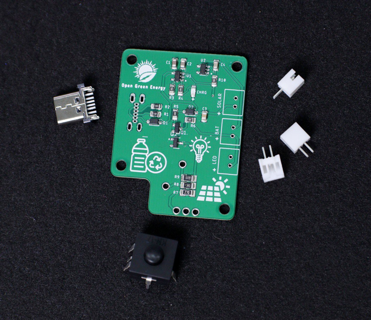
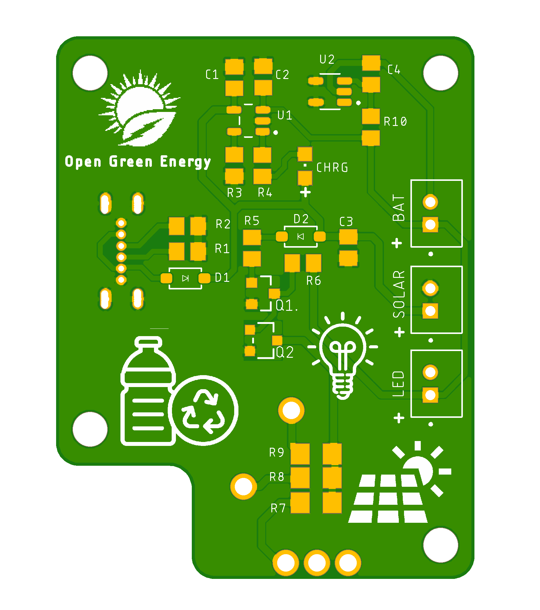
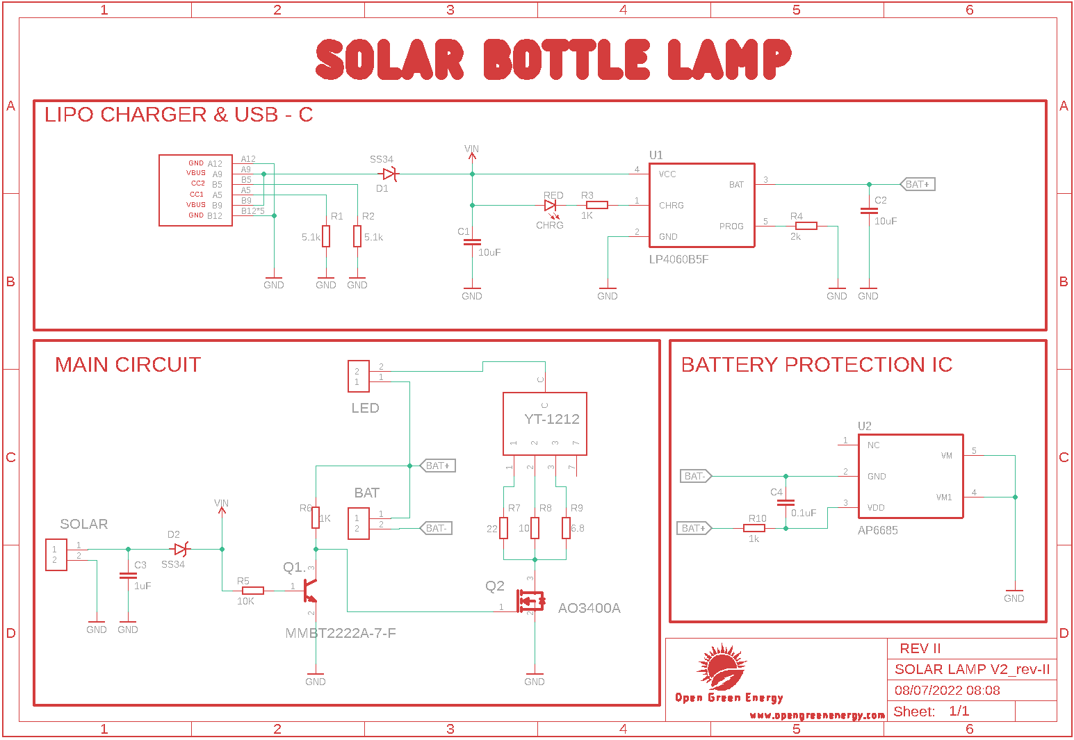
How the Circuit Works?
The entire circuit is broadly dived into 3 parts:
1. Charger Circuit
2. Battery Protection Circuit
3. LED Driver Circuit
The power generated by the Solar Panel is extracted by the charger circuit and charges the battery. The protection circuit is responsible for providing various protections to the Li-Ion Battery. The LED driver circuit is responsible for driving the LED.
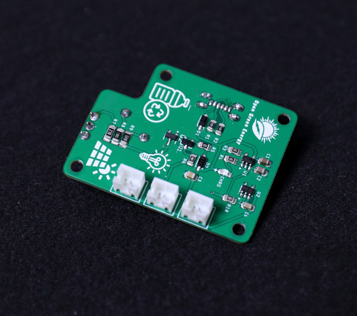
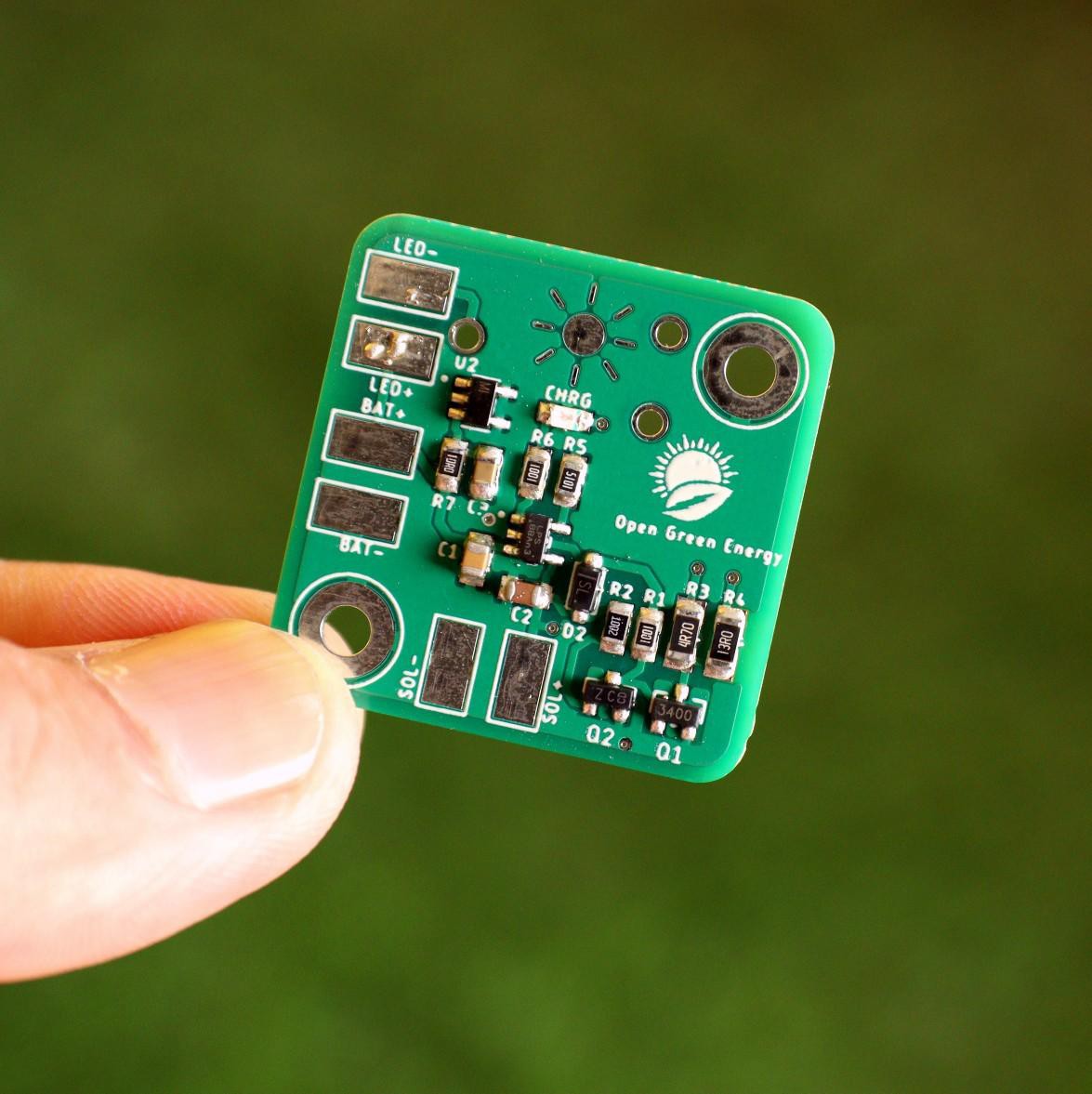
Charger Circuit:
The charger circuit charges the battery by taking power generated from the solar panel. It is based on a lithium-ion battery charger IC LP4060. It is a complete constant-current/constant-voltage linear charger for a single-cell lithium-ion battery. It uses only a few external components like resistors and capacitors. The circuit is based on the application circuit given in the datasheet.
Battery Protection Circuit :
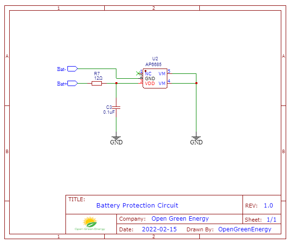
The Battery Protection Circuit provides various protections to the Li-Ion battery. The circuit is based on IC - AP6685 which contains internal power MOSFET, high-accuracy voltage detection circuits, and delay circuits. The IC has the following protections inbuilt:
1. Reverse polarity protection
2. Over Charge Protection
3. Over-Discharge Protection
4. Load short circuit protection
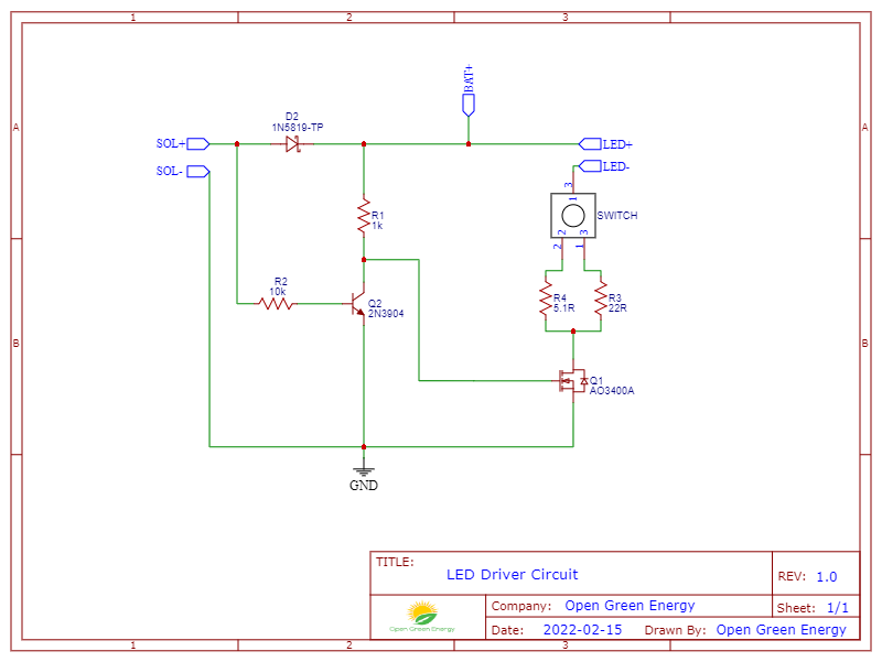
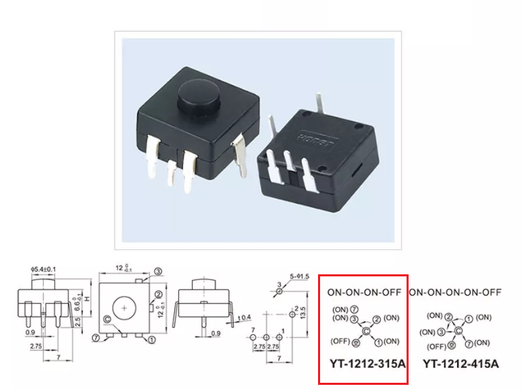
LED Driver Circuit :


 makeTVee
 Nitesh Kadyan
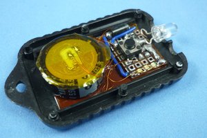
 Absolutelyautomation