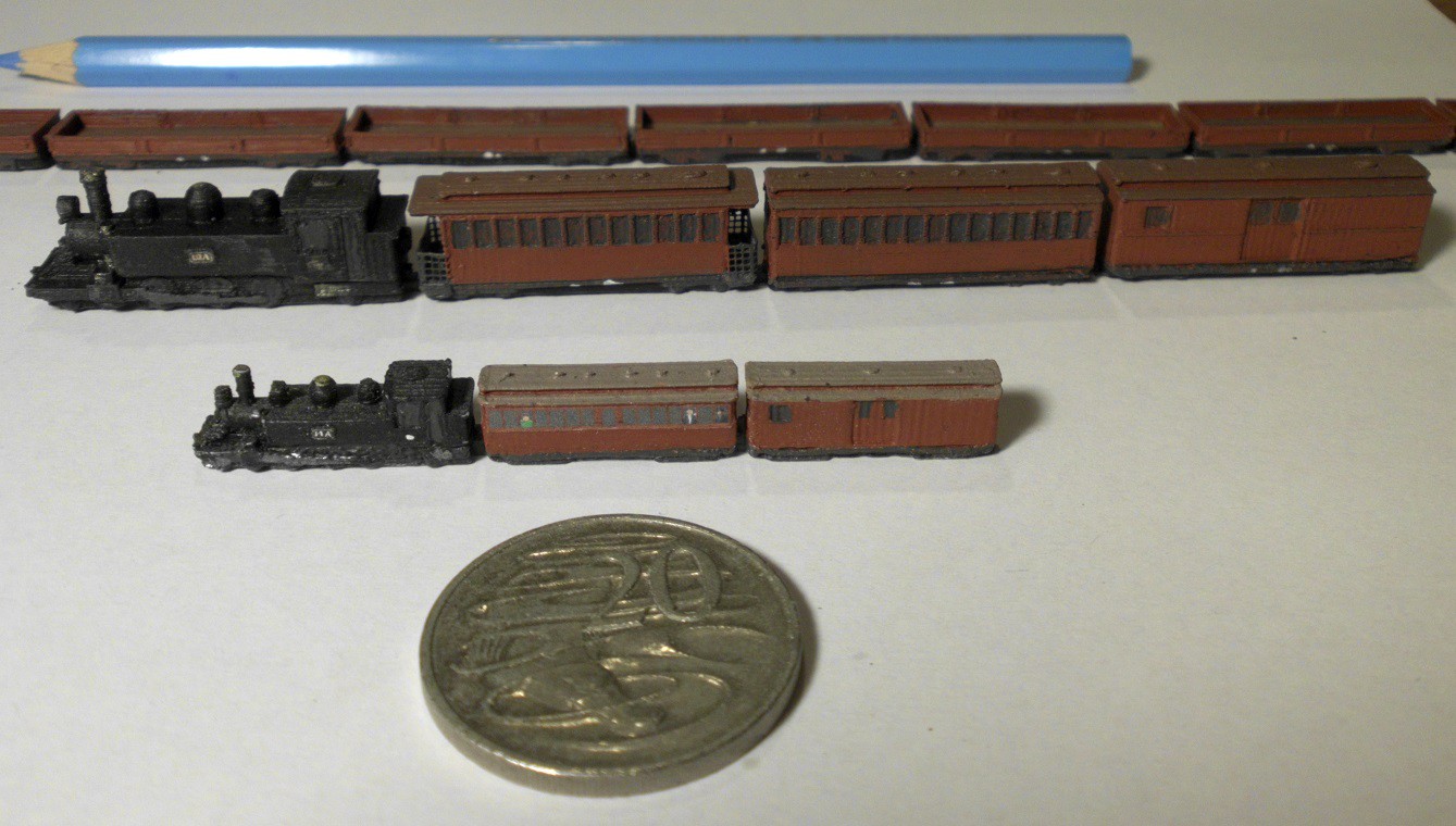
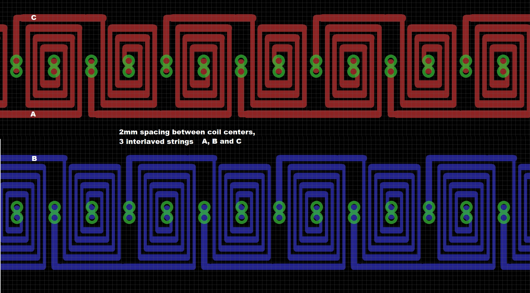
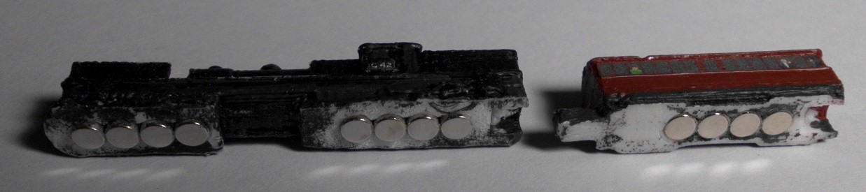
I have been experimenting with using PCB linear motors for small scale model trains, cars, boats, etc. The technology is proving to be very effective for these tiny models, avoiding the usual problems of unreliable mechanisms and poor electrical pickup between the rails and wheels. The track is a 3-phase synchronous linear motor using a double-sided PCB with three interleaved strings of coils. The vehicles all have 4 or more neodymium magnets. The technology is based on a now-expired patent from IDL Motors.
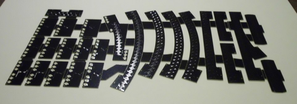
The complete track is built from a variety of small straight and curved PCBs each about 10cm long, which are soldered together into a longer track. The PCB is 0.6mm thick to minimise the gap between the bottom layer of coils and the magnets in the models. The coils are on 4mm centers, alternating between the top and bottom layers to halve the effective coil spacing down to 2mm. With a bit of microstepping, an effective step size of 0.25mm allows very slow movement that is almost smooth. Each coil has 4 turns of wire and is driven at about 0.3-0.4A from either 12V or 15V. The current is set by matching the section length (number of track pieces) to the supply voltage. 2oz copper is used to minimise the resistance and so increase the practicable section length to 1.0-1.5m. The 3-4W of dissipated heat from each section is spread over this full length and so is not a problem. Most projects need multiple sections, controllers, and power supplies, with my most recent ones each having around 15-20m of track.
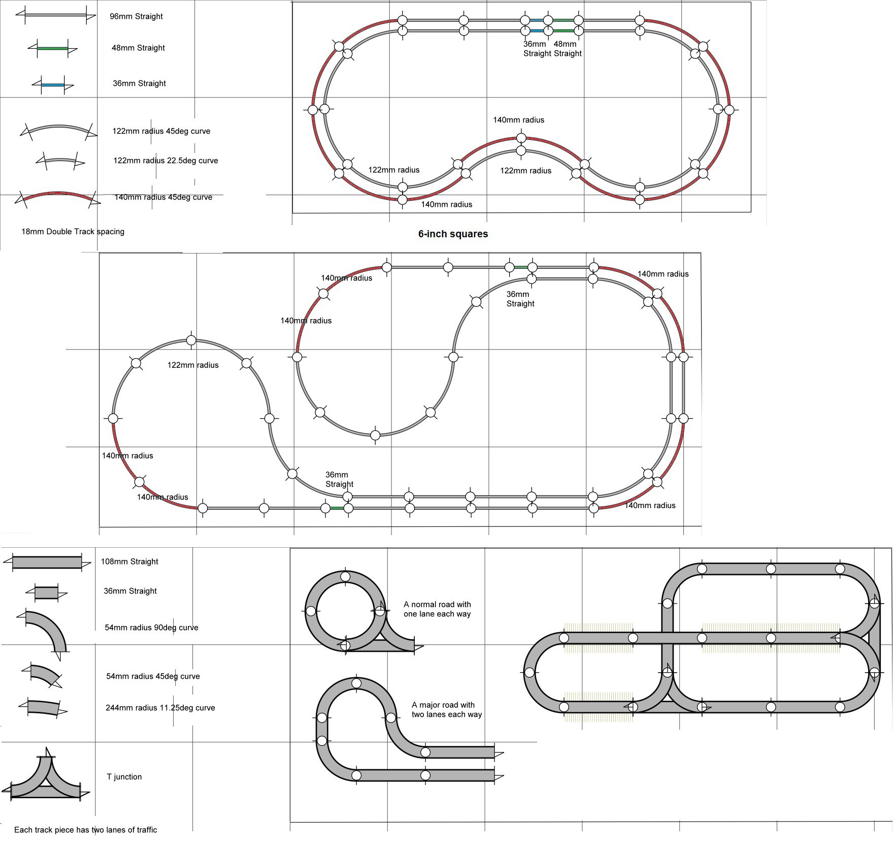
My first experimental track was designed by hand in Eagle, but that process was tedious and very much a dead end. I now use a custom scripting language to define the geometry of each track piece, which then gets compiled into an Eagle script to build the board. I then hand-edit several pieces together into a panelized board for manufacture. With a judicious selection of pieces, one design with a batch of 10 PCBs is enough for a complete project. A similar script and program generates road or rail track artwork for a paper running surface which is glued onto the installed PCB tracks for protection and appearance.
Turnouts and crossings are made from two separate pieces of track, typically a straight and a curve, one on top of the other with only one powered at a time. Other full or partial sections can be switched off to park a train or car, allowing road queues and shunting of trains. Since all 3 wires have to switched together, pairs of DPDT relays are used. Since everything moves in precise lockstep, complex automation is almost trivially easy. A Hall sensor provides the initial position reference.
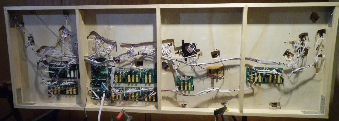
The control unit is a conventional 3-phase motor controller circuit using 6 MOSFETs controlled by a PIC16F690, although I am switching over to a more capable STM32 (Blue Pill) design. Section switching is handled by one or more daisy-chained relay boards, each with 3 pairs of relays. All wiring uses 3-wire strips of grey IDC cable with plugs and sockets made from IC socket strips. The relay boards have banks of these 3-pin sockets and serve as plug panels, so are fully configurable to make wiring a new design straightforward. Given that my latest project has about 80 relays and 80 3-wire cables, keeping it under control is an absolute necessity!


 Jeroen
 Jarrett
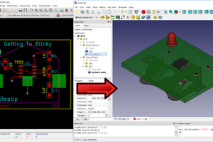
 Maurice
 Rhys
Rhys
I really love this idea, I wonder I could place the PCB between N gauge rails so the rolling stock can use their own wheels.
Would you consider posting an ecample coil layout file? Cheers