I had the choice between designing a custom PCB or sit down and handwire every switch and connect them to the microcontroller board. I decided for the latter, even though that meant soldering for hours on end. And, as it turned out later, my mediocre soldering skills lead to some reliability issues.
Still, I think handwiring was the best option for a first prototype. Below I describe my process which makes it look tidy and organised. The QMK documentation gives a great first introduction into handwiring. It also compares a bunch of different approaches, of which I chose to follow the one by cribbit. In that case, diodes are wired column-to-row, and attached to the row wires of the matrix. The column wires are soldered to the switches directly. Then the MCU board is connected. This blog post by Dave is interesting as well.
Switch Matrix
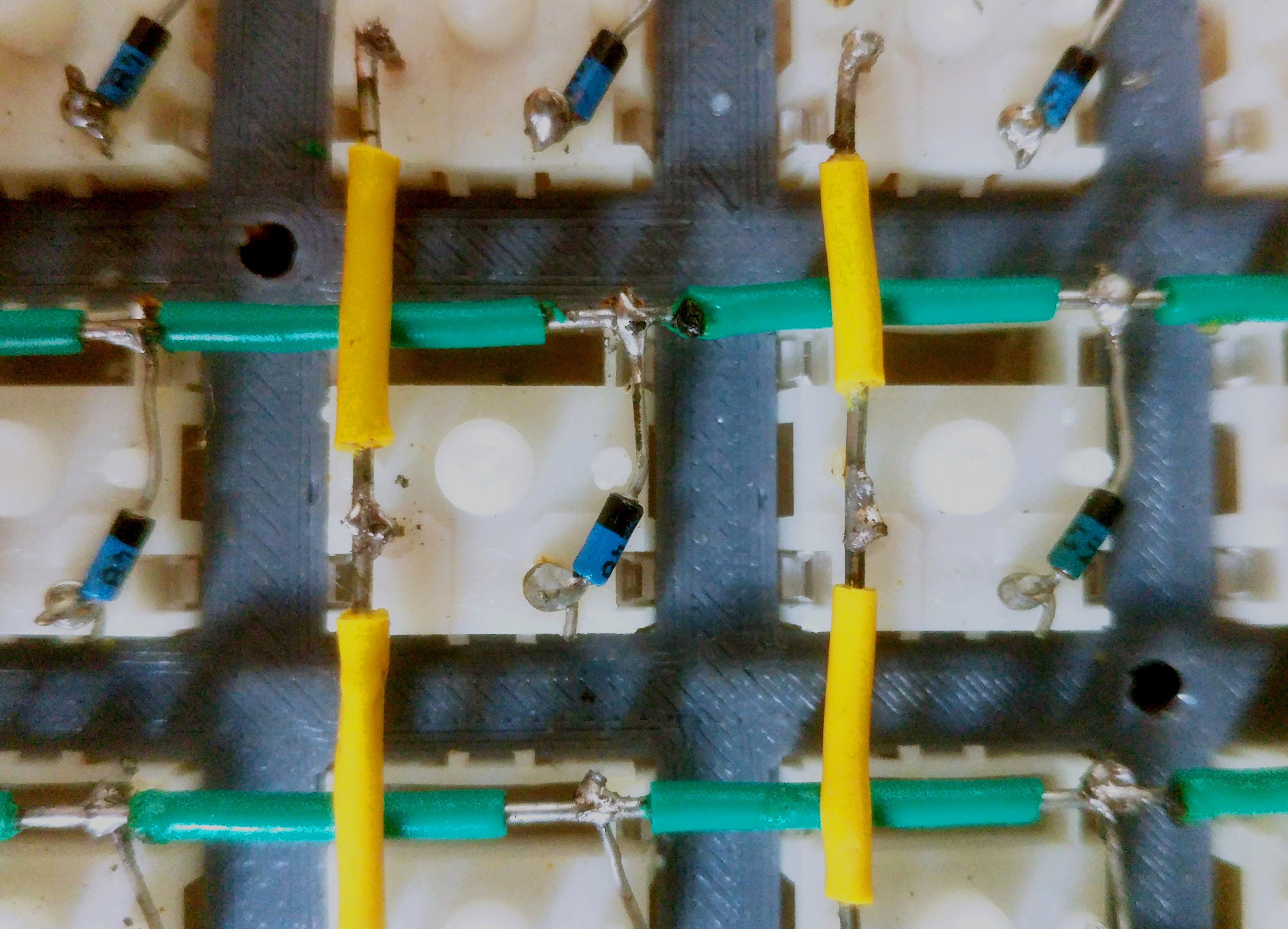
First, a loop is made in the cathode lead of the 1N4148 diode, places onto the pin of the switch and tightened, then soldered. I regret not making a loop on the opposite anode end of the diode. It resulted in me having to re-solder the joints of a couple of switches later on. For the switch matrix, I used 20 AWG solid core wire which is rigid and easy to bend. I cut around the insulation and pushed it along the wire to expose only the part of the wire where the joint was located. After that, it looked like this:
Saving an MCU Board Pin
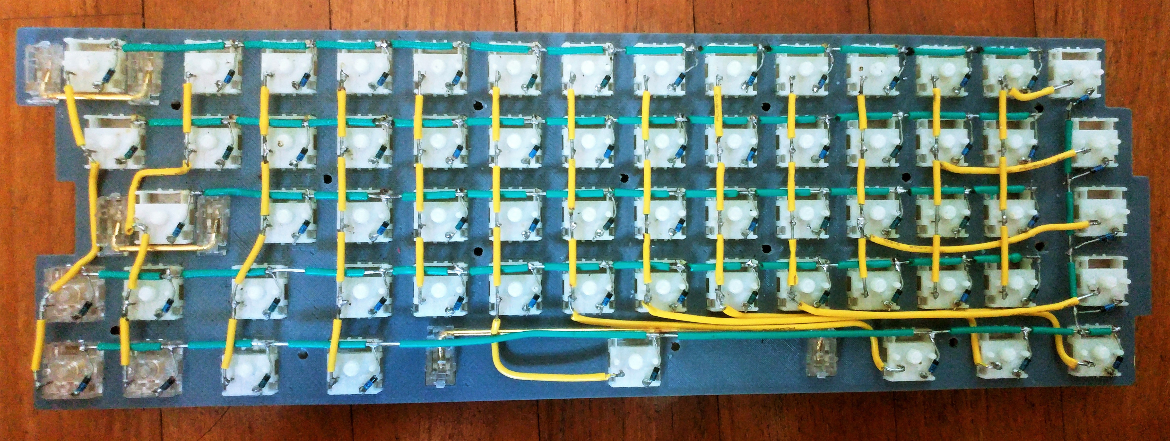
I need to admit a bit of a miscalculation. The ProMicro board has 18 usable inputs. However, I have designed my layout to be 14x5, which would require 19 pins. I worked around it by wiring the last matrix column as part of the bottom row as seen in the picture below. While that works perfectly fine, you'd be better off getting a board with at least 19 inputs (such as the Teensy 2.0).
MCU Board
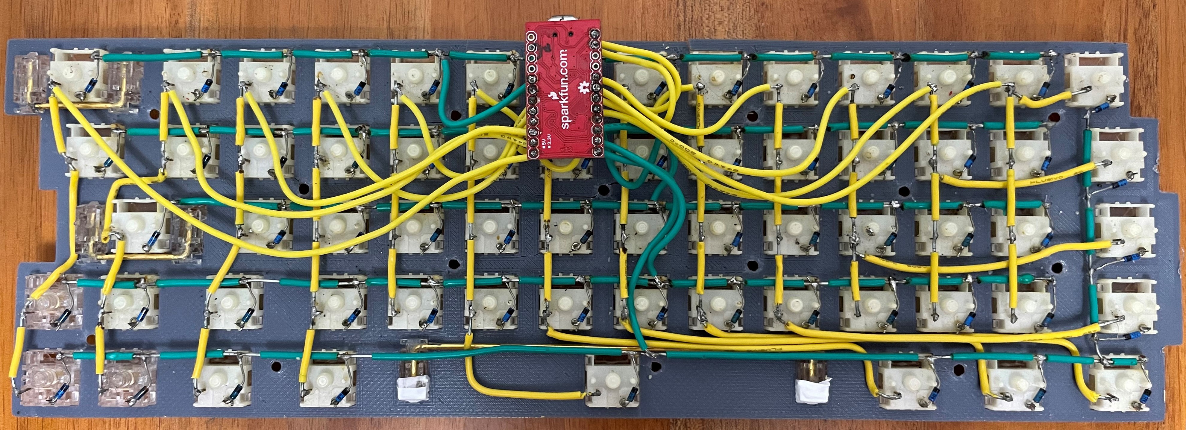
The position of the MCU board is – as determined by the case design – in the middle of the upper edge. To connect the board to the rows and columns, I used 24 AWG stranded wire. It is very flexible which helps with the assembly. All pins of the ProMicro can be used except GND, VCC, RST and RAW.
It does not matter where on the row or column the wire is soldered to because it is all connected anyways. Choose the wire lengths so the MCU board can still be lifted from the plate by around 1 cm. If it is shorter, the assembly will be difficult. But too long and it will be tough to accomodate all the wiring in the tight spaces of the case.

Discussions
Become a Hackaday.io Member
Create an account to leave a comment. Already have an account? Log In.