 Dan Julio
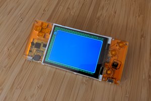
This is the photo (courtesy e-Design product page) that excited me and caused the purchase. Accurately measuring the value of SMT parts in-situ? In a stylish package? Yes, please.
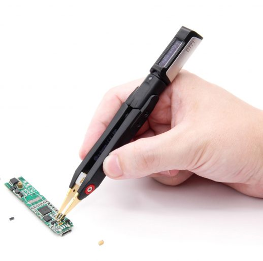
The display portion is connected to the battery-carrying tweezer section using a 4-conductor audio-style plug allowing it to rotate for easy view. An accelerometer allows the OLED display to flip orientation based the device's position in the hand. The DT71 can act as a basic multimeter (minus current monitoring) as well as generate some waveforms and supposedly measure the value of components in a circuit. I suspect that there is a wanna-be Jony Ive at e-Design because the reality is definitely form-over-function. In reality the device isn't particularly accurate, doesn't do a good job of identifying parts in a circuit and uses a gimmicky capacitive touch button that is often accidently triggered, or even worse, mis-calibrated when the device starts up and then won't work at all. Despite all that, the DT71 is useful as a simple DMM or for stand-alone part value measuring.
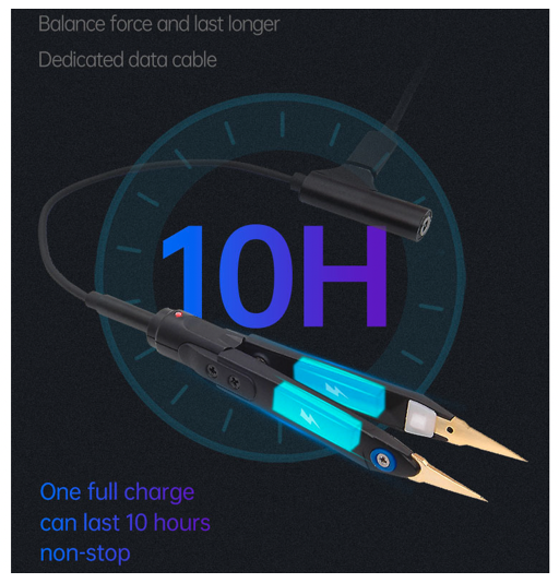
In order to charge the meter, or to load a firmware upgrade, a USB-C cable assembly is plugged in between the two parts. Firmware upgrades are as easy as dropping the binary on a volume that appears when the USB-C cable is plugged into a computer but charging is bit convoluted. Here's another marketing image from e-Design showing the cable charging the batteries. Clearly the four connections between the two halves are used for multiple functions.
The display seemed operational when my device failed so I guessed the problem to be a connection issue with the probes. Removing all screws in the tweezer section revealed no easy way to disassemble the tweezers and it soon became obvious glue was involved. A lot of glue. Sadly my attempts to pry the tweezers apart resulted in damage to the flex PCB that wraps around the connector at the top and extends down both legs to connect to the battery and probe at the end. Aside from all the broken plastic, the destroyed flex PCB dashed all hopes of fixing the unit. I never found the problem but I'm pretty sure that a trace on the flex PCB was broken. Maybe flexing a flex PCB isn't always a good idea.
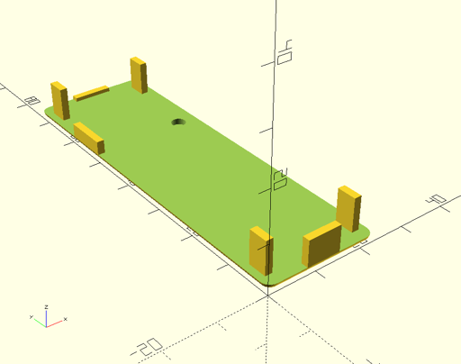
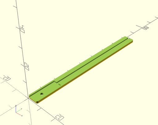
On to plan B. I would make a new base. But first I had to figure out how everything was wired. Fortunately the flex PCB was reasonably easy to decipher and I created a schematic. The only real circuitry in the tweezer section is the battery charger based around a SOT23-5 device. I couldn't find a match for the ID printed on the chip but research revealed that it's a standard pin-out compatible with common American and Chinese chips. I'm guessing it's a TP4054 variant or clone. The two tiny 50mAh 3.7 LiPo batteries are connected in parallel and the charger configured for 50 mA maximum charge current. Interestingly, e-Design used two small RED LEDs, connected identically, for charge status. I guess they wanted to evenly illuminate the charge indicator diffuser. Here's the schematic (which, really, is the most interesting part of this post). Pretty simple.
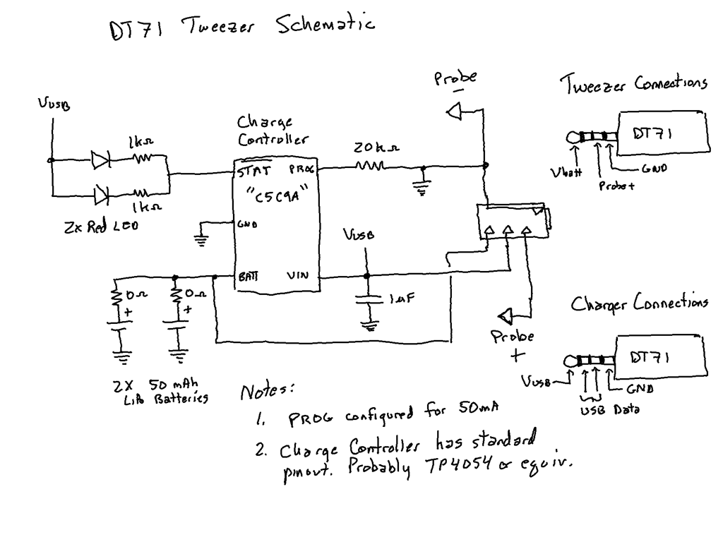
The other interesting thing I found was the pin-out of the of the 4 conductor plug on the display unit and the way it decides if it is connected to the tweezer section or USB charge cable assembly. In retrospect, "of course", but it took a second to guess that supplying 5V to the power input of the display module would be a good signal that it was being powered by USB rather than a LiPo battery (max typ 4.2V). Then firmware switches the middle bands of the connector to the USB interface rather that one of them connected to an ADC (that, through other circuitry, is connected to the meter's positive probe). The meter's negative probe is connected to common (no measuring negative...
Read more »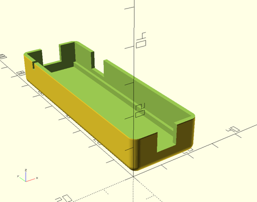
 deʃhipu
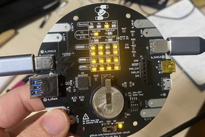
 Spencer Maroukis
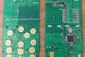
 Mastro Gippo
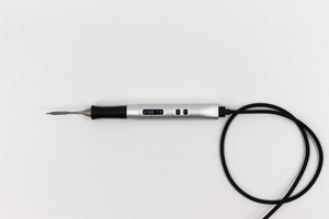
 Nicolas Schurando