 Joseph Marlin
Over the last three months I have completed most of the 3D printed structural components of the cat feeder, and so I have moved on to the brains of the operation.
The requirements for this project, as I assigned to myself back when I first started are:
- Aesthetically pleasing
- Secure - not vulnerable to my cats robbing it anytime they want a snack
- Configurable remotely via network (Wifi)
- Solid construction
- Ease of maintenance
- Low food warning
- Food capacity for two weeks or more
- Painless food refilling process
- High reliability
With these requirements in mind, I set off to design the circuit board that will control the cat feeder. I knew right off the bat that I would be using the ESP8266 based Wemos D1 Mini, because I've used them before and they are perfect for this - WiFi connection, small form factor, and sufficient IO for the project.
Besides that, the other interfaces that would be needed are:
- Ultrasonic distance sensor
- To sense when we're running out of food
- Addressable LEDs
- To make the crystal glow all pretty
- Motor control
- To move the cat feeder wheel.
Next, I set off to gather some parts. Here are the ones I selected:
- Ultrasonic distance sensor: HC-SR04
- Motor: Uxcell Dual Shaft 10RPM Wormgear Motor
- LEDs: WS2812B White, 5 meters 30 LEDs/meter, IP65, LED light strip
- Power Supply: 10A 5V Power supply
- Wemos D1 Mini
After gathering these materials, I began the board design. I chose to start with 5V and use a boost converter to supply 12V to the motor. Although power motors with a boost converter can be tricky, I felt that making a 10A power supply to supply the hungry hungry LED strip would be more trouble than it was worth. The LEDs 1.8A per meter at full brightness white. Although I expect to operate them neither at full brightness, nor full duty cycle, nor always white, it nevertheless seemed more appealing to me to start with 5V and boost to 12V for the motor.
Here's what I developed:
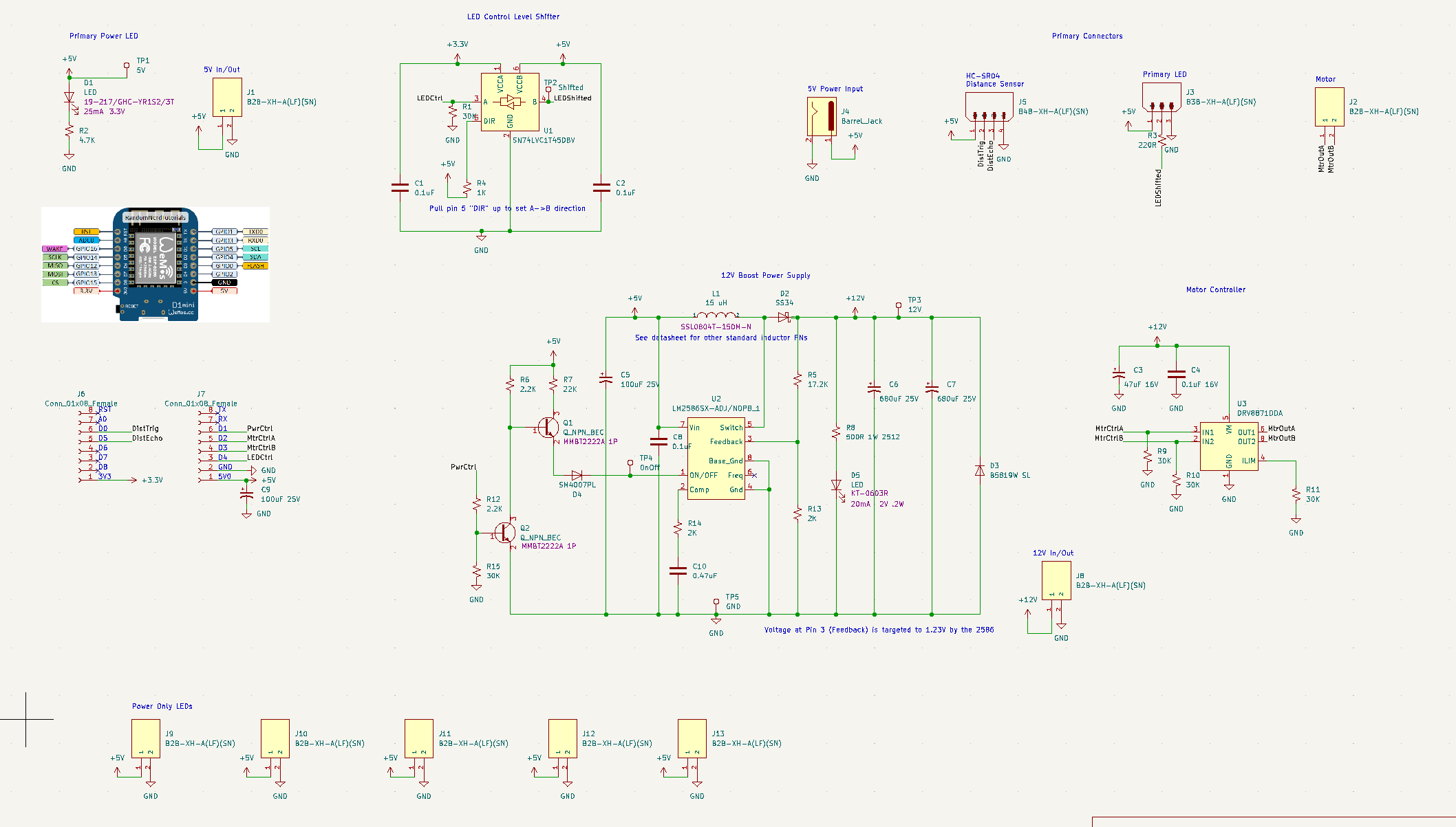
Multiple 5V power supply ports are available in order to power the LEDs - the control line can be daisy chained and each segment can have its own power port, keeping the current on the wires limited. I'm unsure if I'll be using that feature though.
I also included a level shifter - the 8266 uses 3.3V logic, and although that could work with just a few LEDs, the long strand of WS2812B programmable LEDs I am baselining made me want to supply a 5V signal.
Next we have the LM-2586-ADJ. This is the adjustable version, that required a specific ratio between R5 and R13 to ensure the output was 12V. There is a 12V specific version, but my board manufacturer, JLCPCB, didn't have it in stock.
You might also be confused by the weird looking double-BJT. This is because Pin 1 is dual use. It is the on/off pin, and it is also a frequency adjustment pin. You can either pull the pin high to shut down the chip, or leave floating to enable the chip. If you pull it down, the frequency adjustment mode gets activated. Thus, the double BJT scheme provides both an inverter from the ESP8266 control signal, and ensures it is floating, not pulled down, when the chip should be active.
Lastly, I put in a DRV8871DDA H-bridge controller ship. Although I don't need to turn the motor both ways, this gives me the capability should I decide I want it. It also just provides an easy way to turn the motor on and off besides simply killing the power supply.
Next came layout, which ended up being fairly straightforward.
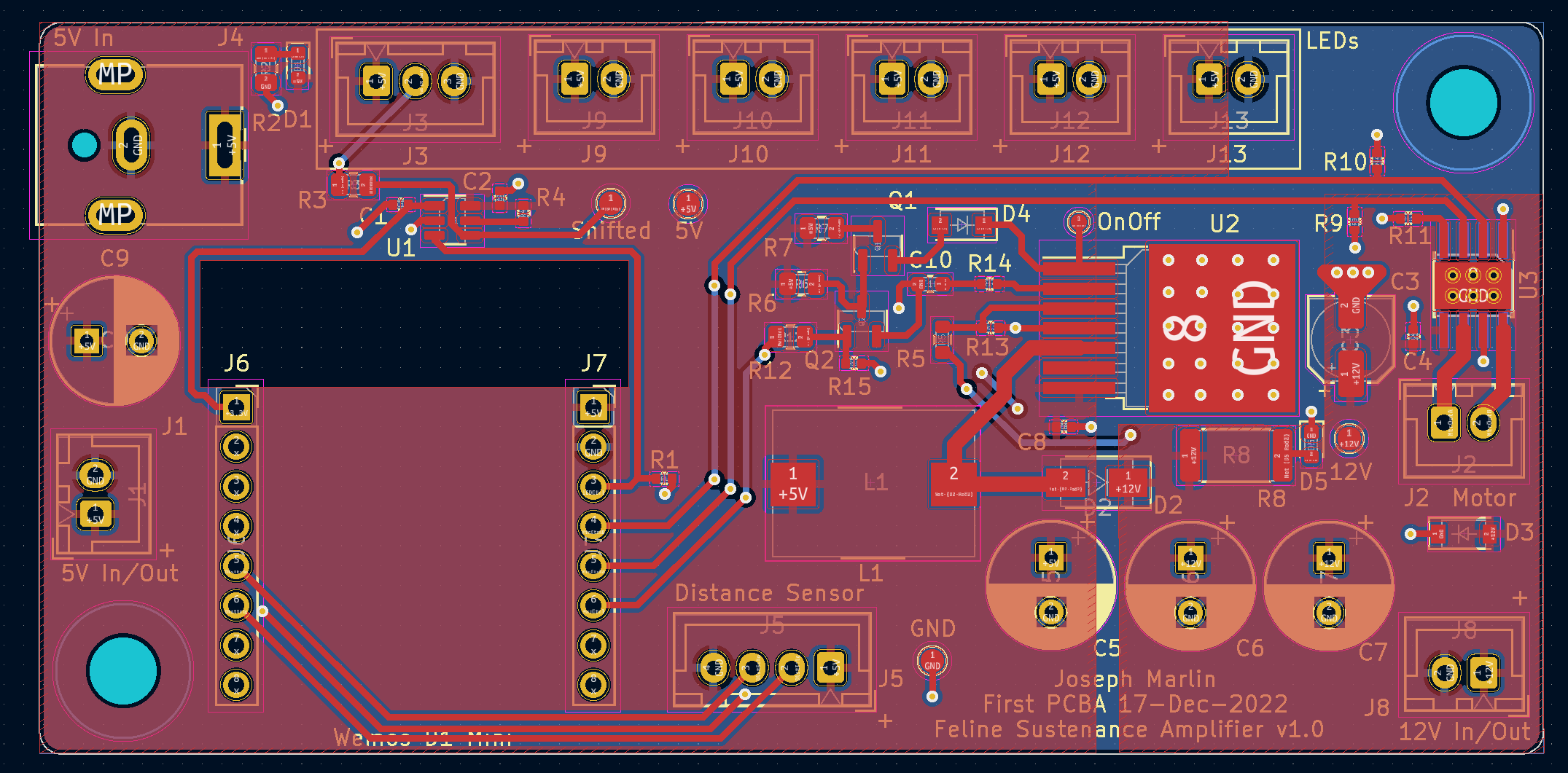
I used KiCAD for this, and the tool is fairly easy to use. The 5V side of the board is on the left, the LED ports on the top. The 12V regulator is center and H-bridge is far right. I also provided 5V and 12V access, at the recommendation of an engineer I found on Fiverr who reviewed my PCB for me. This allowed me to both supply and source these voltages externally should it be needed some day.
I put a lot of capacitance on the 12V side to supply the inrush for the motor, and was surprised to see that there is no good way to calculate how much capacitance you might need. My Fiverr reviewer was also concerned that the power draw from the motor might drop the 5V supply enough to cause the ESP8266 to reset, so I added more capacitance on that side too.
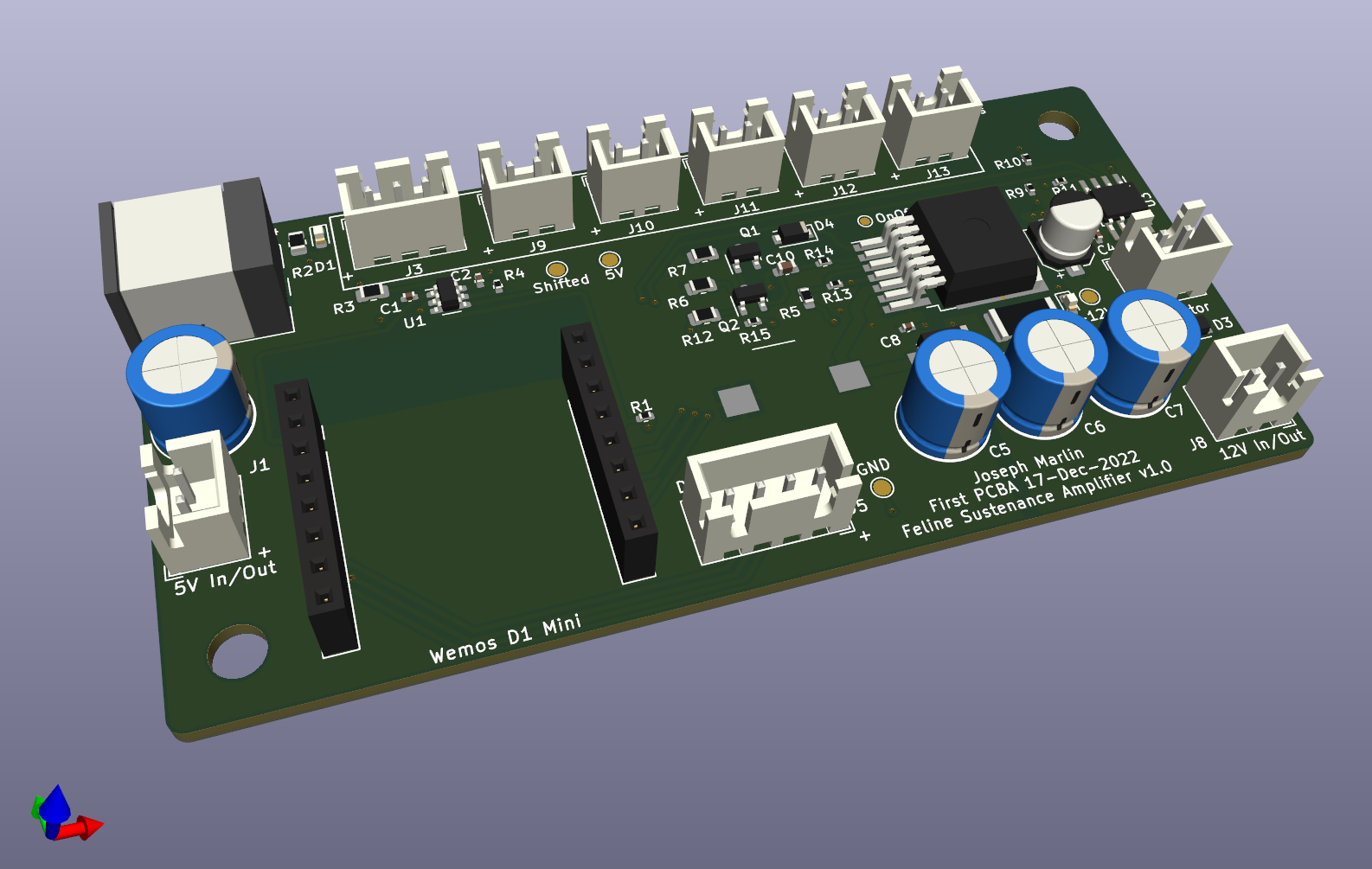
Finally, designed and ready to build, I headed over to JLCPCB. I opted to have two assembled, which I envision using as a "dev unit" and a "production unit". One to hack around on and figure out the problems, and one to use on the actual cat feeder.
Finally, the big day arrived, and I received the boards.
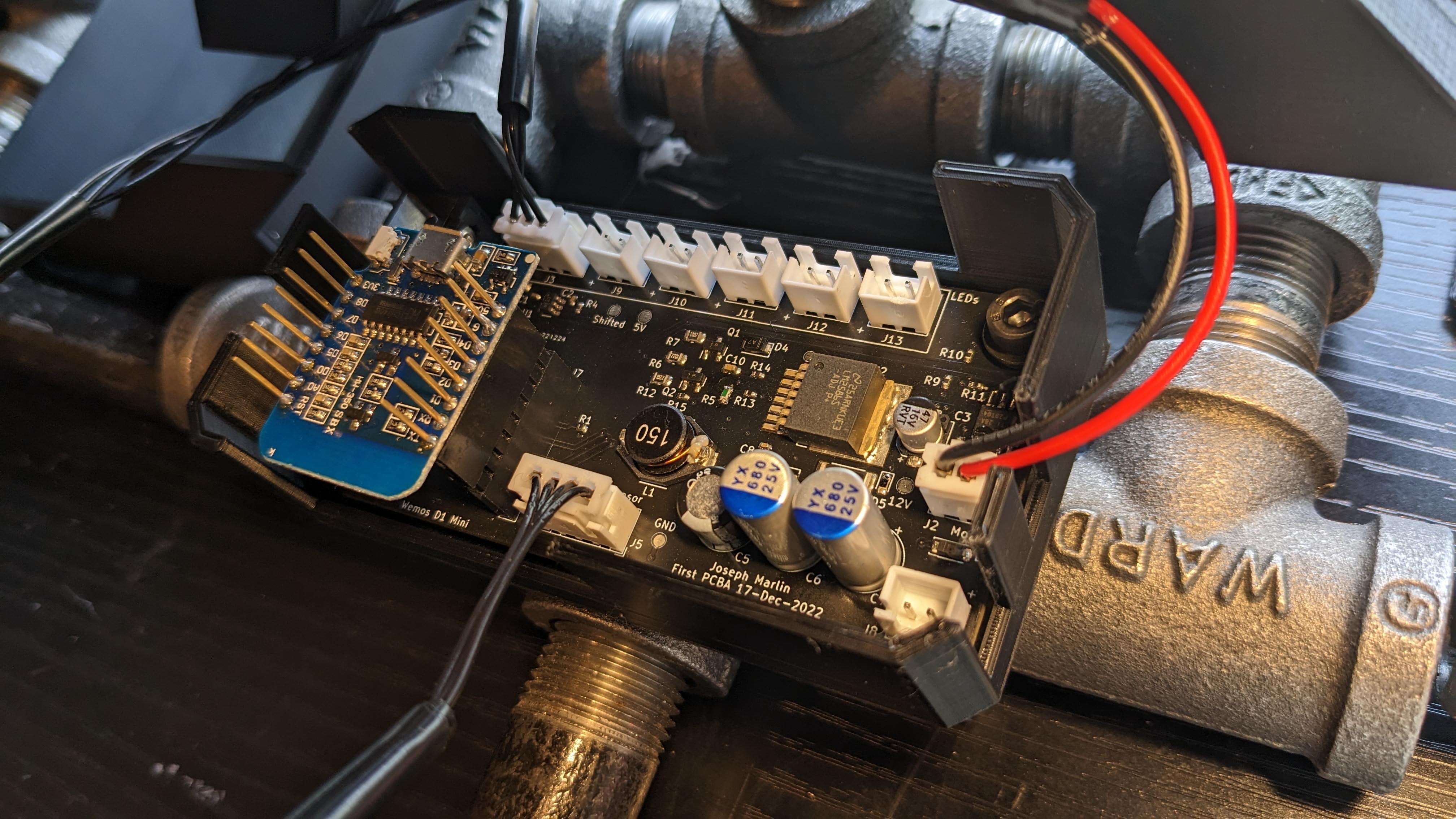
I carefully began turning on the circuits, one at a time, and I am thrilled to say it substantially works right out of the box. Of course, no PCB is perfect on the first try - here are the issues I found:
- 5V is present on the 12V rail all the time 12V is not enabled.
- The only down side of this is that the 12V indicator LED is on all the time.
- 12V ends up being 11.75V, pretty good, probably due to tolerance in R5 and R13
- I reversed the pinout of the ESP8266 so it is backwards. This makes the USB hard to access while mounted, but otherwise is ok.
- Case did not fit because
- the caps are taller than expected/modeled
- the now-reversed 8266 extends past board outline.
- 12V LED is wildly bright
- D3 diode let out magic smoke when 12V enabled for the first time - symbol is backwards in KiCAD.
- Haven't replaced it and have not seen any ill-effects from flyback yet.
None of these issues blocked progress though, so I've been continuing to work on the code that will operate the actual cat feeder, which I will share as the next log. The distance sensor works marvelously. The motor turns smoothly and exhibits no issues. The LEDs light and are controllable with no issues. I am not currently using any of the extra power ports, but I also used relatively small wire, so I may have to eventually.
Discussions
Become a Hackaday.io Member
Create an account to leave a comment. Already have an account? Log In.