 ElectronicABC
GERBER:
https://mega.nz/file/acAWma5Q#ed9cgokmjMIU7K_00HJpkmdlGlZWzoHIBPuECt96UhE
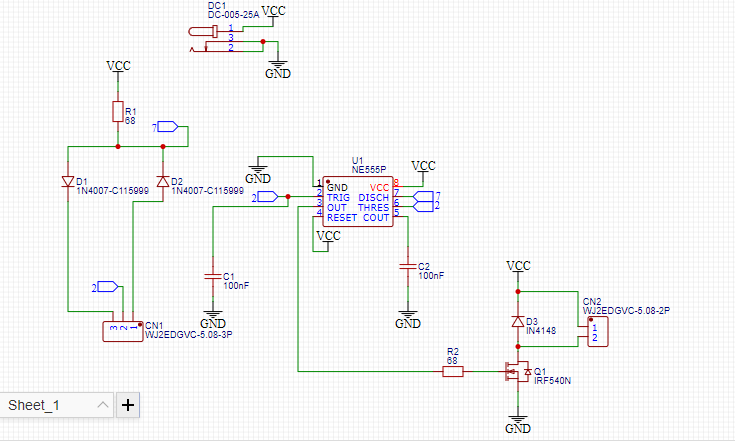
PWM stands for Pulse Width Modulation where the pulse width modulation is made up of a square wave signal that does not always have the same ratio between the time it is high and the time it is low.
The pulse width variation consists of varying the on and off times, that is, Ton and Toff. By changing the value of a PWM, these times are actually being modified.
The truth is that by varying the duty cycle of a PWM signal, what we are doing is varying its average voltage.
When an average voltage signal passes through certain electronic components, it can cause their behavior to change. For example, LEDs, DC motors or fans, even loudspeakers and buzzers.
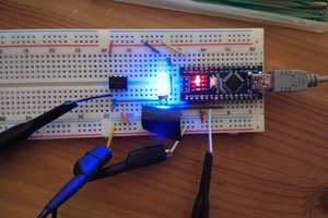
If we have an LED connected to this regulator, we can vary the brightness with which the LED lights up by varying the signal through the potentiometer.
If we send it a 100% duty cycle signal, the LED will turn on at full power and therefore at full brightness. If we subject it to a 50% duty cycle signal, the LED will turn on at half its brightness.
Another option may be to control the speed of a DC motor, for example those used by some PC fans, although it can be used with any DC motor.
When the duty cycle varies, the speed varies as the average voltage in the motor winding varies. At 100% duty cycle, the motor will rotate at full speed. By reducing the duty cycle, the speed will be reduced.
ELECTRONIC COMPONENTS
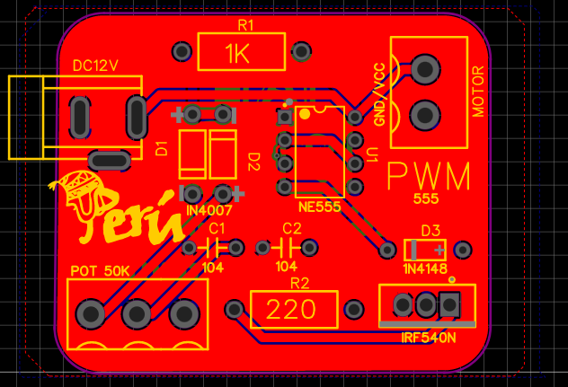
· A 1K 1/4W resistor
· One 10K 1/4W resistor
· One 500K potentiometer or preset
· Two 10 nF capacitors
· One NE555 integrated circuit
· Two 1N4148 diodes
· An IRFZ44N mosfet transistor
· A 12v power supply (Current according to consumption)
· Two 100nf capacitors
FEATURES:
· VIN 5V – 15V DC
· HIGH OUTPUT FREQUENCY RANGE
· OPTIMAL OUTPUT LEVELS
· IMAX OUTPUT 1A
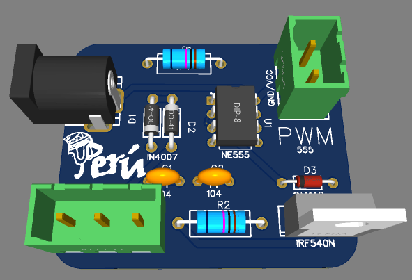
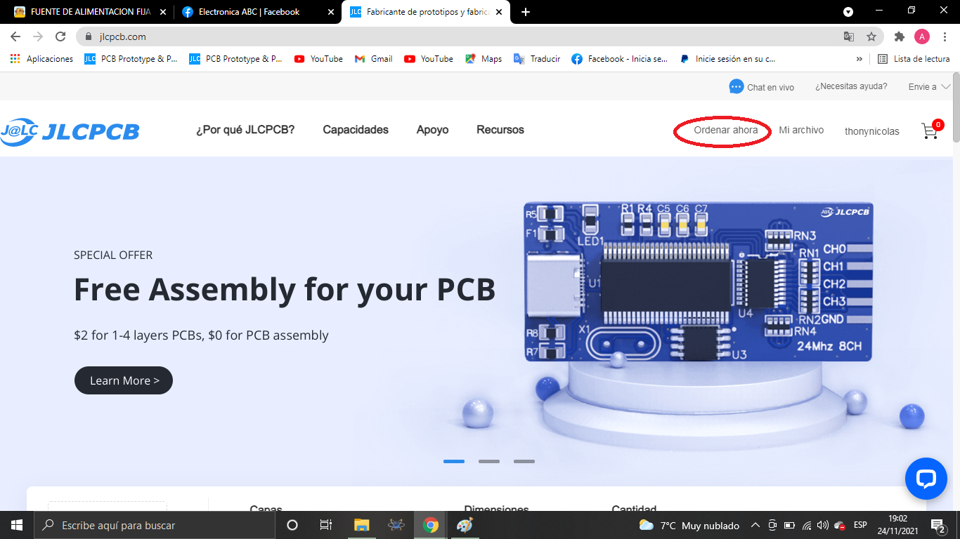
We thank JLCPCB for professional PCBs
Order your PCBs here
5PCBS AT $2
GERBER PCB:
https://mega.nz/file/acAWma5Q#ed9cgokmjMIU7K_00HJpkmdlGlZWzoHIBPuECt96UhE
 Mrinnovative
 Simone Tolomei