Mrinnovative
DIY-Calculator-using-Arduino

Performing simple mathematical operations was the basis on which one of the first computing machines designed by Charles Babbage who is considered as the father of computers was a steam-driven machine used to compute tables of numbers.
In this tutorial, we will build our own simple calculator using an Arduino and 4×4 keypad and display the result on a 16×2 dot matrix LCD Screen. Our calculator will be able to perform Addition, Subtraction, Multiplication, and Division. If you want to create your own mathematical function, you can do the same.
Just play around with the program and you will understand.
COMPONENTS REQUIRED
Breadboard
Arduino Uno
Arduino Uno Programming Cable
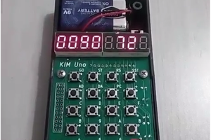
4×4 Keypad
16×2 LCD Screen
Jumper Wires
10kΩ Potentiometer

CIRCUIT DIAGRAM
In this diagram, we can see that there are eight pins coming out of the 4×4 Keypad. It has 4 pins for rows and 4 pins for columns.
These 8 PINS are driven out from 16 buttons present in the MODULE. Those 16 alphanumeric digits on the MODULE surface are the 16 buttons arranged in MATRIX formation. These are mostly used for the control system or embedded systems where we need to give some command to the system to perform a given task
or when we need to perform multiple tasks but with a smaller number of pins.

Understanding how 4×4 Keypad works is a little tricky. The module only has 8 pins to interface 16 buttons. To understand consider we have connected the pad to a microcontroller now set all the rows to output and set them logic HIGH that is 5V.
Now set all the columns to INPUT to make them sense logic HIGH.

Now as the key is pressed at ROW 3 and COLUMN 2, the current flows as shown in the figure. As all Columns are inputs sensing high, so controller sense that logic HIGH is present at C2 pin and store it in its memory that button pressed is in Column 2.

Now all Column pins are set HIGH and all Rows pin are set as INPUT to sense the incoming logic HIGH.
Now the current flows as shown in the figure and Microcontroller sense that Pin R3 is getting Logic High, so button pressed is in Row 3 and it knew that button is in Column 2 from earlier settings. So in this way, the controller senses which key is being pressed on the keypad.
ARDUINO CODE EXPLANATION
First, you have to make sure that you have the necessary libraries installed in your Arduino IDE from the links given below-
For LCD screen library see https://www.arduino.cc/en/Reference/LiquidCrystal
For 4*4 Keypad Library download from https://github.com/Chris--A/Keypad
Start the code by including the libraries in the code and then define the keys on the pad. Put in the pins, the Keypad and LCD screen is connected to. Create the keypad variable, so that you don’t have to deal with the identification process of the pressed key, let the library take care of it.
#include <LiquidCrystal.h>
#include <Keypad.h> // Download library for Keypad from https://github.com/Chris--A/Keypad
const byte ROWS = 4;
const byte COLS = 4;
char keys[ROWS][COLS] = {
{'1','2','3','A'},
{'4','5','6','B'},
{'7','8','9','C'},
{'*','0','#','D'}
}; // defining the keys in the keypad
byte rowPins[ROWS] = { 2, 3, 4, 5 };
byte colPins[COLS] = { 6, 7, 8, 9 };
Keypad kpd = Keypad( makeKeymap(keys), rowPins, colPins, ROWS, COLS );
Now initialize the serial monitor and start giving the inputs from the keypad to the Arduino. The functions defined in the code will take the input and display the result on the LCD screen. Make sure that you press the ‘#’ button to get the result after pressing the numbers and operand.
The arithmetical operations will be performed by-
Character on Keypad
Assumed to be
‘A’
Addition (+)
‘B’
Subtraction (-)
‘C’
Multiplication (*)
‘D’
Division (/)
‘*’
Clear (C)
‘#’
Equals (=)
The final result will be updated in the second line of the LCD screen as shown and given by the following code-
void DisplayResult()...
Read more »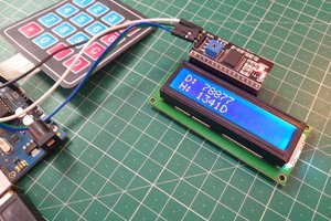
 Sagar 001
 Arduino Enigma