 Lithium ION
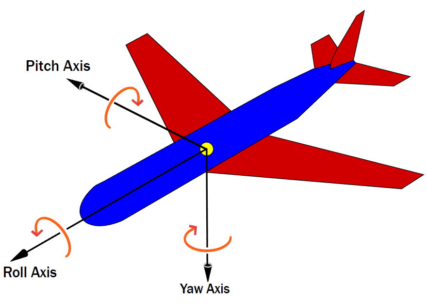
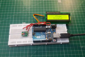
Three Axis gyroscope sensors are very useful in making like flight controllers, ship/boat controllers, direction prediction and controlling the Microcontroller accordingly. In today’s tutorial, we will discuss about MPU6050 gyro sensor and make a small project to know the functionality. Which can show Pitch, yaw and roll readings on display.
Gyroscope v/s Accelerometers:
Gyroscope sensor is a device that can measure and maintain the orientation and angular velocity of an object. These are more advanced than accelerometers. These can measure the tilt and lateral orientation of the object whereas accelerometer can only measure the linear motion.
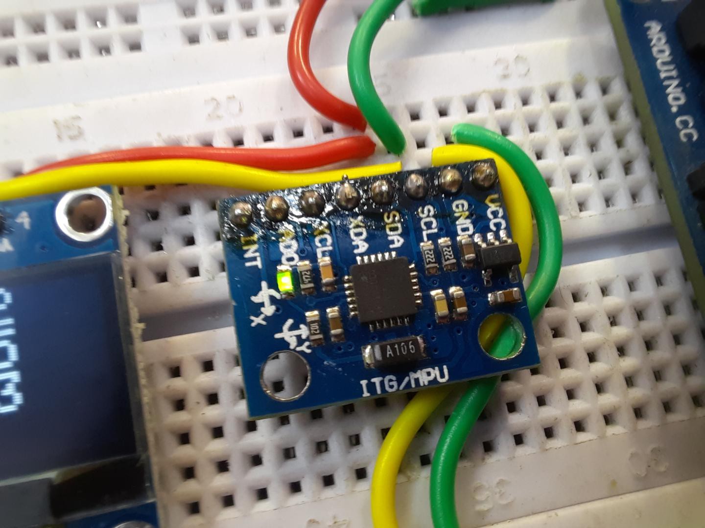
MPU6050:
MPU6050 is a Micro Electro-mechanical system (MEMS), it consists of three-axis accelerometer and three-axis gyroscope. It helps us to measure velocity, orientation, acceleration, displacement and other motion like features. which processes complex 6-axis MotionFusion algorithms. The device can access external magnetometers or other sensors through an auxiliary master I²C bus, allowing the devices to gather a full set of sensor data without intervention from the system processor.
Features:
· MEMS 3-aixs accelerometer and 3-axis gyroscope values combined
·Power Supply: 3-5V
·Communication : I2C protocol
·Built-in 16-bit ADC provides high accuracy
·Built-in DMP provides high computational power
· Can be used to interface with other IIC devices like magnetometer
·Configurable IIC Address
·In-built Temperature sensor
Measuring Acceleration:
The MPU6050 can measure acceleration using its on-chip accelerometer with four programmable full scale ranges of ±2g, ±4g, ±8g and ±16g.
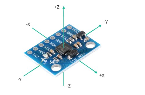
The MPU6050 has three 16-bit analog-to-digital converters that simultaneously sample the 3 axis of movement (along X, Y and Z axis).
Measuring rotation:
The MPU6050 can measure angular rotation using its on-chip gyroscope with four programmable full scale ranges of ±250°/s, ±500°/s, ±1000°/s and ±2000°/s.
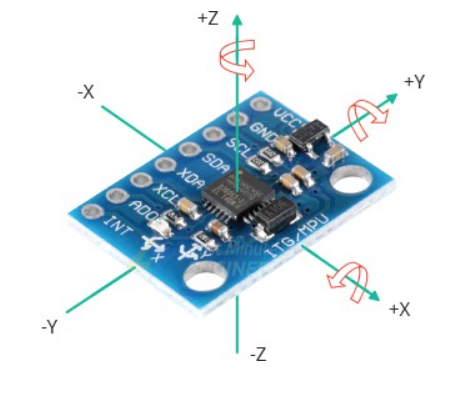
The MPU6050 has another three 16-bit analog-to-digital converters that simultaneously samples 3 axes of rotation (around X, Y and Z axis). The sampling rate can be adjusted from 3.9 to 8000 samples per second.
The I2C Interface:
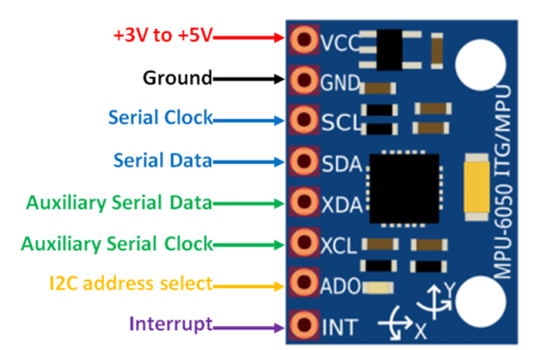
The module uses the I2C interface for communication with the Arduino. It supports two separate I2C addresses: 0x68HEX and 0x69HEX. This allows two MPU6050s to be used on the same bus or to avoid address conflicts with another device on the bus.
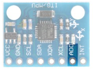
The ADO pin determines the I2C address of the module. This pin has a built-in 4.7K pull-down resistor. Therefore, when you leave the ADO pin disconnected, the default I2C address is 0x68HEX and when you connect it to 3.3V, the line is pulled HIGH and the I2C address becomes 0x69HEX. To can also check the address of I2C, follow this link here.
Adding External Sensors:
To increase the level of accuracy even further, the MPU6050 module provides a feature for connecting external sensors. These external sensors are connected to the MPU6050 via a second I2C bus (XDA and XCL), which is completely independent of the main I2C bus.
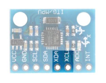
This external connection is usually used to attach a magnetometer, which can measure magnetic fields on three axes. By itself, the MPU6050 has 6 Degrees of Freedom (DOF), three each for the accelerometer and the gyroscope. Adding a magnetometer adds an extra three DOF to the sensor, making it 9 DOF.
Components required:
1) MPU6050
2) OLED I2C
3) ARDUINO UNO
4) POWER SUPPLY
5) BREADBOARD AND WIRES
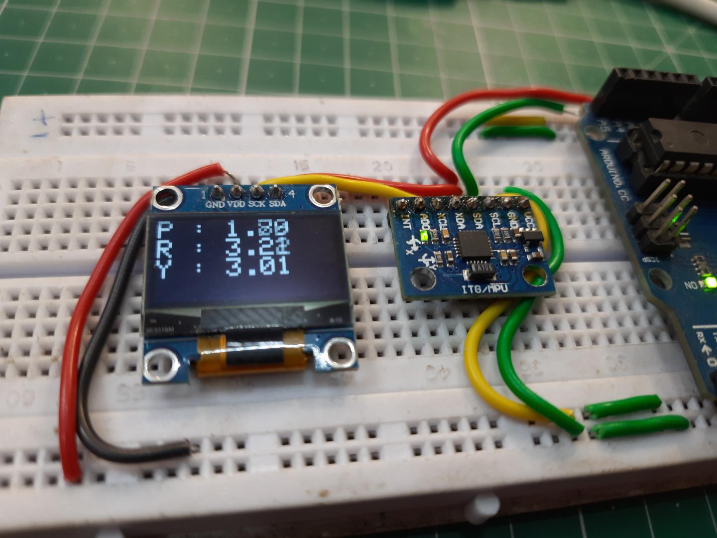
Circuit representation:
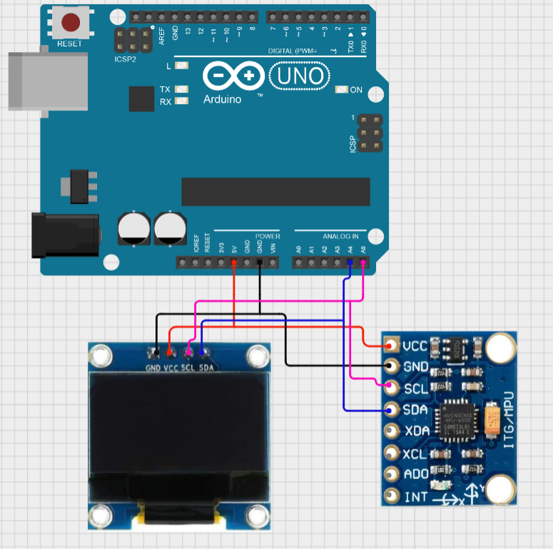
MPU6050 and OLED both can be connected easily using I2C protocol. So, we changed the address and connected them in parallel with microcontroller. A 5volt supply is enough to power up whole the system.
Want to make your Own microcontroller board:
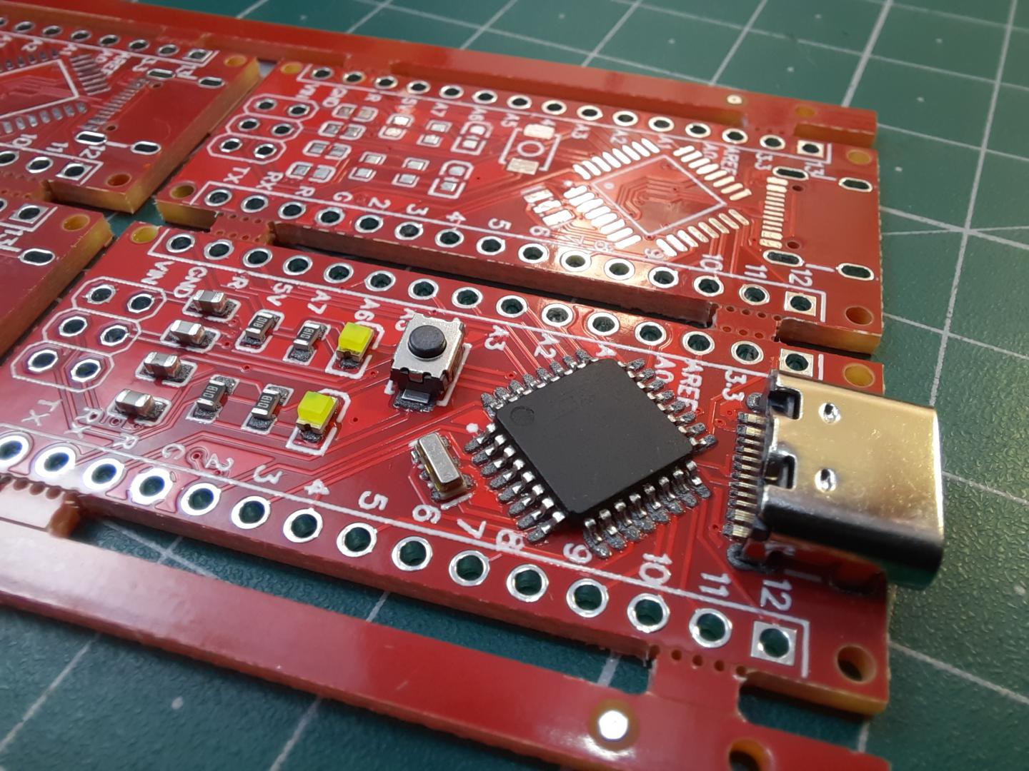
If you want to make your own Arduino, like...
Read more »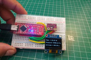
 Sagar 001
 Tom Meehan
 Hulk
Hulk