 Sagar 001
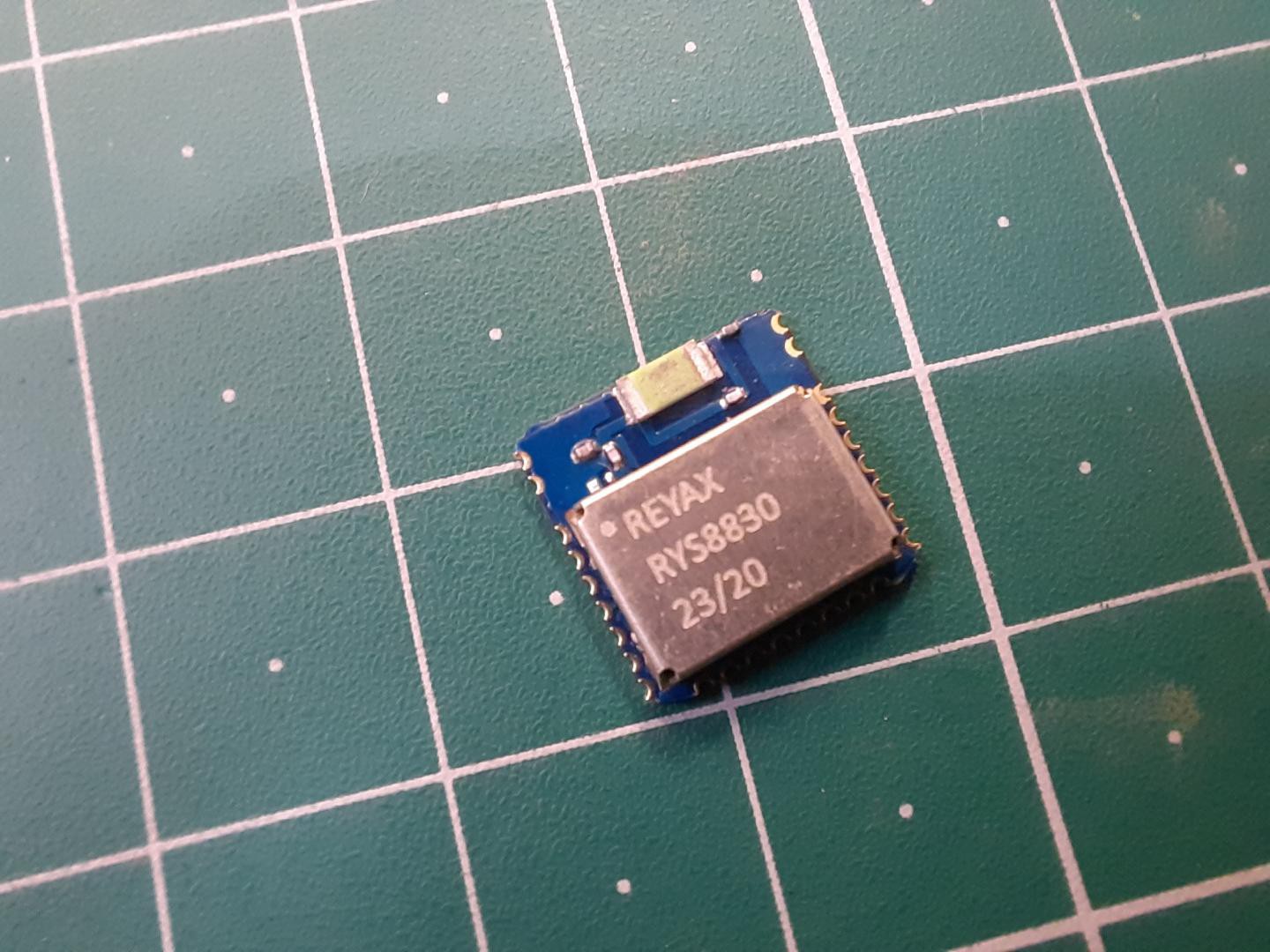
In this post, we will learn how to use Reyax RYS8830 GPS/GNSS Receiver Module to retrieve time and position data from satellite navigation systems. The RYS8830 module from Reyax is based on Sony CXD5605GF/CXD5605AGF technology & comes as a small SMD component. The RYS8830 GNSS modules can be used in tracking devices that need to be small and power-saving. The Reyax RYS8830 has a small form factor and ultra-low power consumption. The GPS/GNSS Module can be interfaced with any microcontroller & can be operated using a simple coin-cell battery.
The RYS8830 Module is a very small SMD Module and requires a PCB. So, in this tutorial, we will use an evaluation board (RYS8830 EVB). The RYS8830 Evaluation Board has an embedded power circuit along with the CP2102 Chip & a micro-USB port. So the board can be directly connected to the computer and using the GNNS Software you can start learning and exploring the feature of RYS8830 Chip.
What is GNNS (Global Navigation Satellite System):
GNNS stands for Global Navigation Satellite System. It refers to a constellation of satellites providing signals from space that transmit positioning and timing data to GNSS receivers. The receivers then use this data to determine location.

The performance of GNSS is assessed using four criteria:
1. Accuracy: the difference between a receiver’s measured and real position, speed, or time
2. Integrity: a system’s capacity to provide a threshold of confidence and, in the event of an anomaly in the positioning data, an alarm
3. Continuity: a system’s ability to function without interruption
4. Availability: the percentage of time a signal fulfills the above accuracy, integrity, and continuity criteria
Reyax RYS8830 & EVB:
The REYAX RYS8830 is built on the high performance of the SONY CXD5605GF CXD5605AGF GNSS engine. The RYS8830 modules utilize concurrent reception of GNSS systems offering high sensitivity in a small SMD form factor.
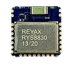
It occupies a small SMD size of 121 mm2, which currently is the smallest GNSS module worldwide with an antenna. The operating voltage is around 1.65~1.95V. The frequency is 1561.098 MHz for BeiDou, 1575.42 MHz for GPS & 1602.5625 MHz for Glonass. RYS8830 has a built-in enhanced GNSS filter, a low noise amplifier, an embedded antenna, and it offers an option of an external antenna. the tracking sensitivity is around -161 dBm.

You can make A fully functional PCB using this module or try the RYS8830 evolution board. Downloadable circuit schematics and Gerber files are provided below. Check JLCPCB prototype service 5 PCB in just $2.
Specifications
1. GNSS Center Frequency: 1561.098 MHz (BeiDou), 1575.42 MHz (GPS), 1602.5625 MHz (Glonass)
2. Navigation update rate: 1 Hz
3. Accuracy: up to 1m
4. Operating Temperature: -40°C to +85°C
5. Dimensions: 11mm*11mm*2.2mm
6. Power Supply Voltage: 1.8V
7. Satellite acquisition Current: 19 mA
8. Satellite tracking Current: 13 mA (GNSS continuous mode)
9. Satellite tracking Current: 2.6 mA to 8.2 mA (GNSS low power mode)
10. Idle Current: 3 mA (GNSS continuous mode)
RYS8830 Evaluation Board
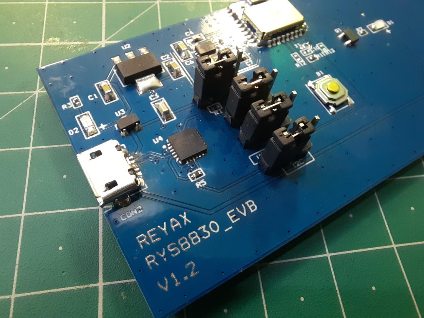
The evaluation board has jumpers for UART or I2C Interface. It also has a reset button for resetting the board or restarting the module. The board consists of a CP2102 Chip which is a USB-UART Driver chip. The micro-USB port can be used to connect the module directly to the computer and also the GNNS Software.
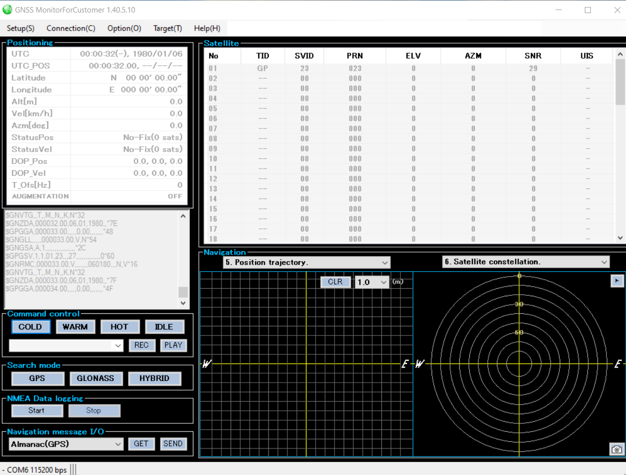
GNSS Monitor Software For Customer:
The GNSS Monitor is a very useful software to evaluate GNSS receiver modules. Using this software, it is possible to connect to the modules to GNSS Transmitter by establishing a serial connection.
The software is very use to use and has user-friendly interface. You can download the software from the following link below:
Download: GNSS Monitor
After downloading the software, you can extract and install it on your PC System. During installation, you may encounter several issues that can be solved by installing proper framework drivers.
PCB layout of RYS8830:
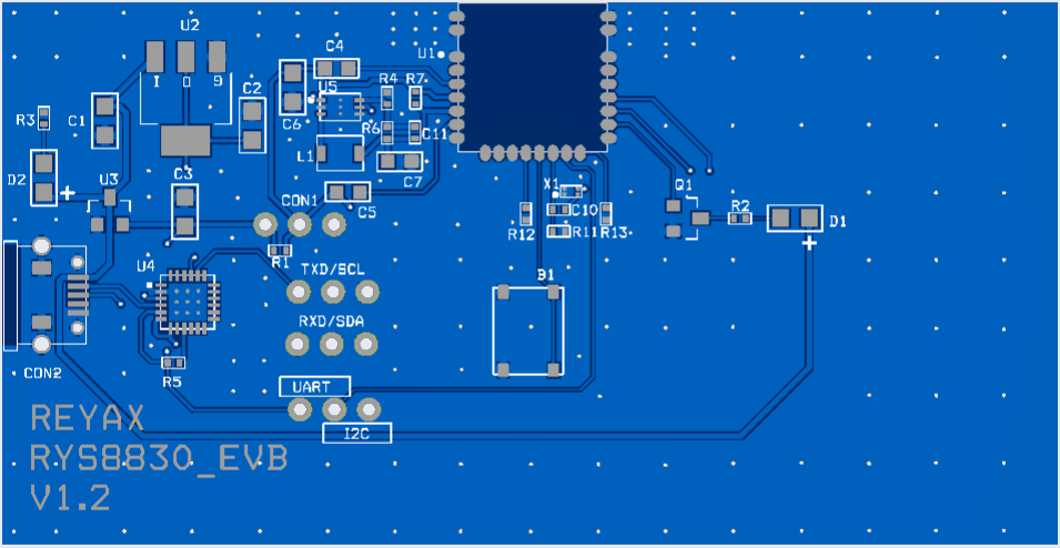
Circuit diagram is provided below with RYS8830 PDF. So, you may change the alignment, color and specifications of your PCB accordingly. Here in the circuit cp2102 USB TO Serial chip can be changed to some cheap solution like CH340G or FTDI232RL. Finally it's Depend on you and if you want to use same design then Download Gerber files from here.
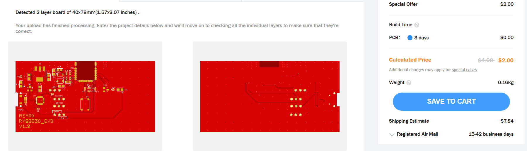
You can order PCB prototypes from JLCPCB, providing 5 Pieces 2layer PCB in just $2. You can choose any color combination, thickness and surface finishing. And if you sign-up using this link, you will get free coupons of worth $30. Checkout JLCPCB right now and get your hands on best services, which may help you to turn your Ideas into Products.
Get Time & Position Data with the GNSS Monitor Software
First we need to establish a connection to the RYS8830 EVB evaluation board with the PC. So use a long Micro-USB Data cable to connect RYS8830 EVB to the computer. Once connected a red light will flash up indicating the evaluation board is correctly powered.
The next step is to start the serial connection between the GNSS Monitor and the RYS8830 EVB:
1. Click on “Setup(S)” in the GNSS Monitor software
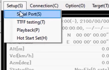
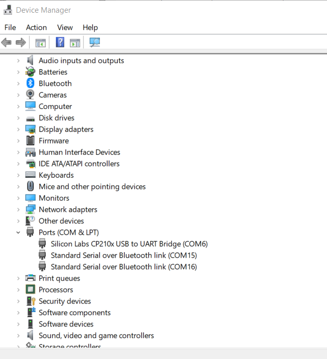
2. Click on “Serial Port(S)”; A new dialog “Serial Port” pops up, correct serial poet can be seen in Device manager of your PC.
3. Now enter the following settings as shown in the image below.
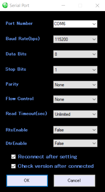
4. At last click on the OK button and a serial connection to the RY8830_EVB will be established
Retrieving Data from the Module
The next step is to start retrieving some data from the module. In general, GNSS receivers offer three modes to start a device:
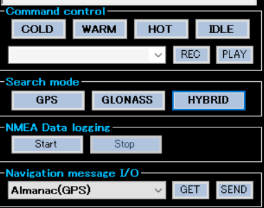
- The hot start is when the GNSS receiver remembers the time (UTC), the last calculated position and a sufficient number of satellites in view (e.g. more than four satellites) and some information about the satellites constellation (almanac). In particular, the receiver used the stored information and makes an attempt to lock onto the same satellites and calculate a new position. The hot start is only applicable when the receiver is started in the same location where it was turned off. The benefit of the hot start is that it does take much less time to get the new position compared to the other modes.
- The warm start is when the GNSS receiver remembers only some data, such as the time, last calculated position, almanac. In contrast to the hot start, the receiver does not remember which satellites were in view. The warm start takes longer than a hot start but not as long as a cold start.
- The cold start is when the GNSS receiver is switched on for the first time or does not remember the previous data. The cold start takes much longer than the other two modes.
![]()
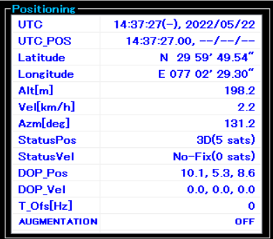
- Since the RYS8830 module on the evaluation board is turned on for the first time, the cold start (COLD) should be pressed. When pressed, a signal is sent to the module and it starts to lock onto some satellites. You should see some log messages and list of satellites. After some minutes, the GNSS Monitor should show the current time and position in the upper left window:
![]()
Important notice:
If you do not get any time or position data, please make sure that the antenna of the RYS8830 module is able to receive signals from the satellites. Usually, the GNSS receiver is not able to receive some signal when placed inside a building (e.g. onto your desk). I used a USB extension cable in order to be still able to work from my desk but having the RYS8830 EVB placed outside of the building.