 land-boards.com
Created Two GitHub Code Development Repositories
- Python Code GitHub (not strictly needed, but helpful)
- Arduino Code GitHub
Python Test (optional)
I have a couple of pieces of Python code that I used to test the connections to the MyMenu card. I wanted to do this while I still had MicroPython (or CircuitPython) running on the QT Py card. This isn't strictly necessary because the MyMenu card connections are checked in the Arduino MyMenu example code later on but it gave me confidence I was on the right path and that the wiring was correct.
I2C Scanner (Python Test Code)
First, I ran a Python based I2C scanner to help debug the I2C connections. When I ran this it showed a list of two device addresses; one for the OLED card and the other for the MCP23008.
MyMenu Test Switches and LEDs (Python Test Code)
I wrote MyMenuPBLEDs.py Python code to test the pushbuttons and OLEDs on the MyMenu card. Pressing buttons displays button code on LEDs and it worked. But it did show some confidence in the functionality of the MyMenu card. It might be useful in the future for Python code development
Why Use Arduino IDE and not just Python?
There's a couple of reasons that I chose the Arduino environment instead of Python for this project. One is code size. The QT Py itself has plenty of Flash memory for an application like this but the RAM turns out to be really small for a decent sized Python application. And from what I can tell when Python does an import it loads the program from the Flash into the small SRAM. By contrast, the C code runs from Flash Memory.
The other is library support. I already have working menu code that works in the Arduino environment. I was really curious just how well existing libraries would play with the QT Py. I had to do a very small amount of tweeking to get the existing code to work. Really all I had to do was remove a couple of errors in the MyMenu and MCP23008 libraries that were doing a test of the CPU architecture type. This code was used to set the I2C speed for the different CPU types. Removing it won't be an issue for other applications. It's tough to figure out the defines for various architectures. This code was used to set the I2C speed and it seems to have been fixed in the Arduino environment with:
Wire.setClock(400000);Setup Arduino IDE support for the QT Py
Followed Adafruit's directions here. Had no issues getting it working. The download process is really simple and doesn't require any button presses which is great since I can't get to button in my board stack-up.
I2C Scanner (from Arduino IDE)
Ran i2c_scanner_wire Arduino code to check the connections to the MyMenu card. Got back the expected result on the USB Serial Monitor:
Scanning...
I2C device found at address 0x20
I2C device found at address 0x3C
done
This shows the OLED at 0x3c and the MCP23008 at 0x20. Both of these are on the MyMenu card.
Why Use the MyMenu Card?
There's just not enough spare pins on the QT Py to read 5 switches. The I2C pins are "free" since they are used already for the OLED. As long as the OLED and MCP23008 I2C addresses don't collide (which they don't) there's no problem. Plus the 3 output LEDs could be used for status.
In fact, there no extra pins free on the QT Py. However, if the INT* line from the MyMenu card wasn't used there would be a free pin. This pin could be used as an analog input and the switches could be connected to these pins with a resistor chain. The QT Py could read the voltage and determine which key was pressed. That is illustrated as something like this (using 3.3V instead of 5V and five switches instead of 6):
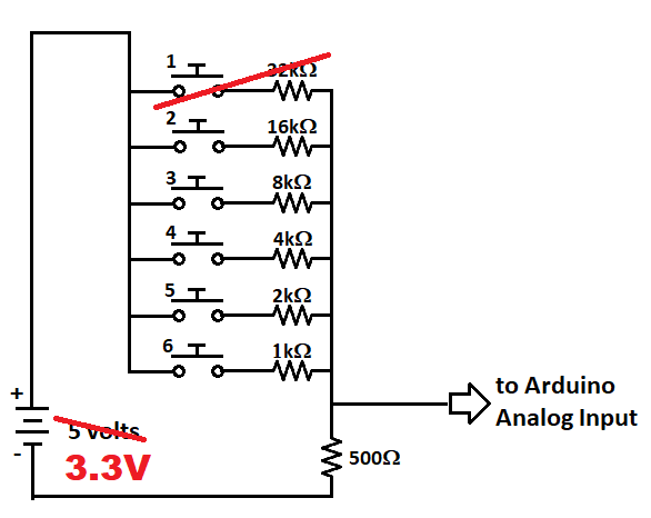
I didn't do this since I have the MyMenu card.
Test SD Card
Ran SD_Dir.ino in Arduino code to dump the directory of the SD card. Only needed to change line that sets the Chip Select to pin 3:
const int chipSelect = 3;
Got back:
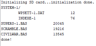
Initializing SD card...initialization done.
SYSTEM~1/
    WPSETT~1.DAT        12
    INDEXE~1        76
done!
It worked!
This displays the System files which are on a "blank" but FAT32 formatted SD card.
SD Card Info
Ran CardInfo.ino code using a "bland but formatted" 8GB SanDisk card. Got back:
Initializing SD card...Wiring is correct and a card is present.

Card type:         SDHC
Clusters:          1936384
Blocks x Cluster:  8
Total Blocks:      15491072

Volume type is:    FAT32
Volume size (Kb):  7745536
Volume size (Mb):  7564
Volume size (Gb):  7.39

Files found on the card (name, date and size in bytes):
SYSTEM~1/     2022-05-14 18:07:06
  WPSETT~1.DAT  2022-05-14 18:07:06 12
  INDEXE~1      2022-05-14 18:07:10 76
This is what I expected. There's some system files on the SD card and nothin else.
Test MyMenu code in Arduino IDE
Ran OLEDMenuCodeV2 code. This is a sample menu program that will be the base of the project. It worked with minor tweeks to the library (described above). The OLED displayed menus. Built-in buttons test option passed.
Test Serial Port
This was a small challenge. The Adafruit M0 library uses the USB for serial. I needed to use Serial1 to write out the actual serial pins instead of the USB serial. I searched the Adafruit notes and forums to find an answer. In the end I just "guessed" that the hardware pins are Serial1 and they were. Ran DigitalReadSerial code with minor tweeks to use Serial1 instead of Serial and to use Pin 2 as the input. Pin 2 is going to be used as the hardware handshake into the QT Py from the target system.
It worked. When I pulled the line high it showed a "1" on the Serial port at 9600 baud, and when I pulled it low it showed a "0". Nice to know that the serial out pin is working and the hardware handshake input pin is reading a bit.
Read a File, Write out Serial
The next step is to read a file from the SD card and write it out the Serial port. I used the DumpFile example code with a couple of simple changes:
// Select the Serial port to send output to
/ #define THESERIAL Serial1 // UART pins
#define THESERIAL Serial    // USB Serial

const int chipSelect = 3;  // SD card Chip Select
The two defines determine which serial port is used for output.
- Serial1 uses the hardware UART pins
- Serial uses the USB Serial
Using the USB Serial for debug.
Loaded a file to the card (CivilWar.bas).
Result is:
The first line should be sent to the OLED as an status message or error message if there's an issue with the SD card access.
Re-Running SD_Dir
Shows the files that I loaded to the SD card are as expected:
Results
This should be all that is needed to write the actual SD Loader application. Should just need to put the pieces together and write a menu program.
Discussions
Become a Hackaday.io Member
Create an account to leave a comment. Already have an account? Log In.