 Emilio P.G. Ficara
Barcode (QR) reader – part 1
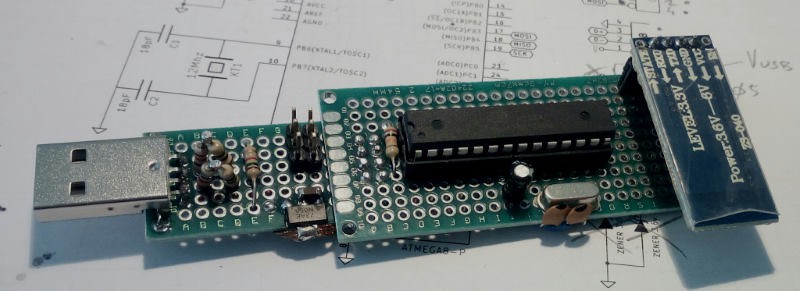
Here's another one of my little weekend projects (in this case, more than one weekend). It is a barcode (and QR) reader that plugs into the PC's USB port and is seen by the system as an HID device, specifically a keyboard. Thanks to this feature, it can be connected to any computer / tablet and can be used from any application (spreadsheet, for example). I tested on WinXP, Win7, Win10 (Windows) and Ubuntu, Debian (Linux) and also on an Android tablet equipped with an OTG cable and the result has always been the same: it works and does not need drivers. Just to understand what it is, let's take a look at the circuit mounted on prototype boards. This is the top view:
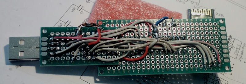
and this one from the bottom (flat cable wires, separated, are best for these jobs)
If someone is already leaving this project because they think it is a bit complicated to build a prototype like this, I invite them to be patient... I have found on-line circuits that are compatible with this application and the next step will be to adapt the firmware to these cheap ones widely used modules, avoiding if possible the use of the soldering iron. Here is also the current schematic:
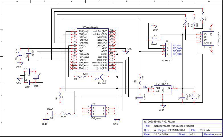
For the more readable version in pdf, load the EF209sch.pdf from the “files” section.
The circuit is based on the ATmega88 microcontroller. It could also be made with other models of the same family, but having only this one in my small mobile laboratory, the choice was forced. To develop the firmware I used a VM with WinXP (which I normally use for the many projects with 8-bit microcontrollers) and on this I installed WinAvr, which is a package containing the C compiler and several other useful tools. WinAvr doesn't have its own IDE, as you can control anything from the command line and use notepad++ (included in the package) for editing source files, but I'm accustomed to using an IDE so I downloaded and installed AvrStudio , the official tool of Atmel (now Microchip). My favourite version for WinXP is the 4.19 which is the last before implementations that unfortunately require you to upgrade (and make slower) the OS in order to work.
At this point, with the software tools available, I went to see an old site, which I have known for years, where there is a library capable of creating a USB device at low speed, using only an interrupt on the micro and a little firmware. This library has changed its name many times and has been continually improved and refined and is used in many devices related to Atmel AVRs, including the famous USBASP programmers. The link to the main page is this: https://www.obdev.at/products/vusb/index.html
I use DuckDuckGo for my internet searches; if you enter the keywords: avr virtual usb, you will be directed there. You will also find several sample projects, supplied with source code and in many cases also with schematics and PCB drawing. A nice site, very well documented.
I went through the list of various projects and eventually downloaded two. By mixing them and making some changes, I finally got what I wanted. Here are the links to the respective pages:
a) 1-Key_keyboard by Flip van der Berg
http://blog.flipwork.nl/?x=entry:entry081009-142605
b) Terminal Keyboard by Neil Stockbridge http: // hobby-electrons. sourceforge.net/projects/terminal-keyboard/
Since the controllers used in both projects were different from mine, I changed the names of some registers (serial port) and then successfully compiled. The AvrStudio IDE also has a part on the right where a list of the internal registers and the individual bits within these registers is available, so it is quite easy to rename those that unfortunately change their name from one model to another, even if a lot similar. In addition to mixing the two programs mentioned and modifying the registers, I also made a small addition: the Terminal Keyboard program (also another by the same author) has a simple entry method, i.e. you send the byte 0xFF followed by the key code (for example, to send an A, send 0xFF 0x04, which is the "scancode" of the a key). I have added a 0xFE. That is… if I want to transmit an uppercase character, I send 0xFF 0x04 (and I get 'A'), otherwise I send 0xFE 0x04 (and I get 'a'). This is because in one case I insert the “left shift pressed” modifier and in the other, no. Immediately after sending the pressed key code, I automatically send the released key code and everything is fine. Since I only want to transmit a barcode, which has a short number of characters, numeric and alphabetic, this level of simplicity is sufficient.
Now, where do I get this data to turn into keystrokes for my simulated "USB keyboard"? Simple, from the serial which in this case is a Bluetooth module type HC-06, which connects to my Android App which does the heavy job, that is, it reads the Barcode (or QR) and transforms the string of characters into a series of commands to be sent via BT to the module. So, I have my smartphone in my hand and I go around reading my barcodes, while the circuit is there, attached to my PC and writes in the application I am using, as if I were there typing on the keyboard. The HC-06 module is set to work as a receiver and has the baud rate set to 9600 bps. The bluetooth name is, in fact, HC-06. Note: If you take an HC-05 and change its name to HC-06 (with AT commands), it works the same.
The zipped hex file serkbd.zip, needed to program the micro ATmega88, can be downloaded from the “files” section. The fuse map is as follows:
lock = FF ext = FF high = C7 low = FF.
The project continues… read the next parts!
Note:
I added a cond. el. from 100uF-16V mounted very close to the power supply pins of the HC-06 module, following a strange event: in some cases, the scan of the BT devices gave me only the MAC address of the module, but not the name! After verifying that this was not an error in my software (using the Nordic nRF Connect tool), I thought about a possible “dirty” power supply coming from the USB socket. With the added capacitor, the problem (at the moment) did not arise again.
Barcode (QR) reader – part 2
Here is the second part of the Barcode reader project. Here I present a small App to test the operation of the hardware card with the ATmega88 micro that I described in part 1. To develop this App I used the B4A tool from Anywhere software. It is a complete development environment that, together with the Android SDK, allows you to write apps for Android (and more!) very easily. The learning time of this “Basic for Android” (B4A) is really short, also thanks to a great forum where you can ask for help in case of difficulty. I recommend everyone to install it to verify how easy it is to develop your own Apps and how useful it is to have a computer as powerful as a smartphone in your pocket. It is not just for going on "social" ...
Downloading and installing the whole environment takes very little time, at most twenty minutes. You can start from this link and follow the instructions step by step, downloading what is requested. When I started using this tool (in 2011) it was paid. It is now COMPLETELY free!
To write this App I started with an example, which you can find at this link . I have done my tests and my changes and I have come to generate the App that I present to you. This App is not published on the “market”, but you can download BTserSend.zip from "files" section.
Here's what the App looks like:
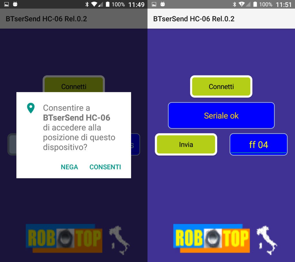
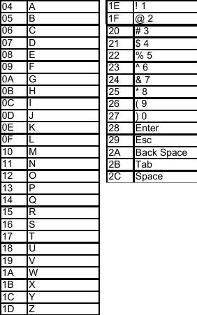
On the left we see the initial screen, in which we are asked to give the authorization to continue. Bluetooth needs it in order to communicate. Next, we will have the control panel with 4 elements. The "Connect" button starts Bluetooth and searches for a device that has the characters "HC-06" in its name. If it finds it, a connection attempt is made on the serial. Attention! This App uses the standard Bluetooth protocol, so if we take a BLE module, such as the HC-10 and with the AT commands we try to change its name to HC-06, the App will be able to see it and try to connect, but there will be a error because the BLE protocol is completely different. For some examples of apps that use this protocol, check out the other articles on my site ficara.altervista.org. Ok, then using an HC-06 type "serial passthrough", if the connection attempt is successful, we will see the message "Serial ok" in the message window below and the "Send" button, previously gray, will turn green (and the button will become active). In the edit window to the right of the "Send" button, it will be possible to insert the couple of hexadecimal characters that you want to transmit to the circuit with the HC-06 module. You can use upper or lower case and separate fields with spaces, but the only characters allowed are numbers [0] to [9] and letters [A] to [F]. If you use other characters you will see a short error message. Once the pair of hexadecimal numbers has been written, you can press “Send” and the code will be transmitted. If our circuit is connected to a USB port on our computer, each transmission will correspond to a character received as if it had been typed on the keyboard (I recommend opening a notepad to do the tests). I remind you that if the first byte is FF, a character is transmitted with the shift key pressed, while if you start with FE the shift key is not pressed. At the moment I have left the freedom to enter any value for the two bytes (it can be useful for other projects), but in the final App (the actual Barcode reader) there will only be FFxx or FExx pairs. For the scancodes relating to the various keys, you can consult the table relating to the keys pressed in this one PDF document (chapter 10). A reduced version, with only the keys that will be used in the project, is visible in this figure:
Barcode (QR) reader – part 3
Here we are finally at the third part, the Android App able to read the barcode (or QR) and transmit it to the circuit connected to the USB of the computer. I have always developed this App with B4A (see references in part 2 of this project) and also this time I started from an example application found on the B4A forum at this link .
I tried this example (and others too) and I made the changes to adapt it to my case, then I joined this part to the previous one (the Bluetooth) to finally get an App that scans a barcode and transmits the characters , via Bluetooth, to my receiver which is seen by the PC as a USB keyboard.
This App is not published on the "market", but you can download it from “files” section.
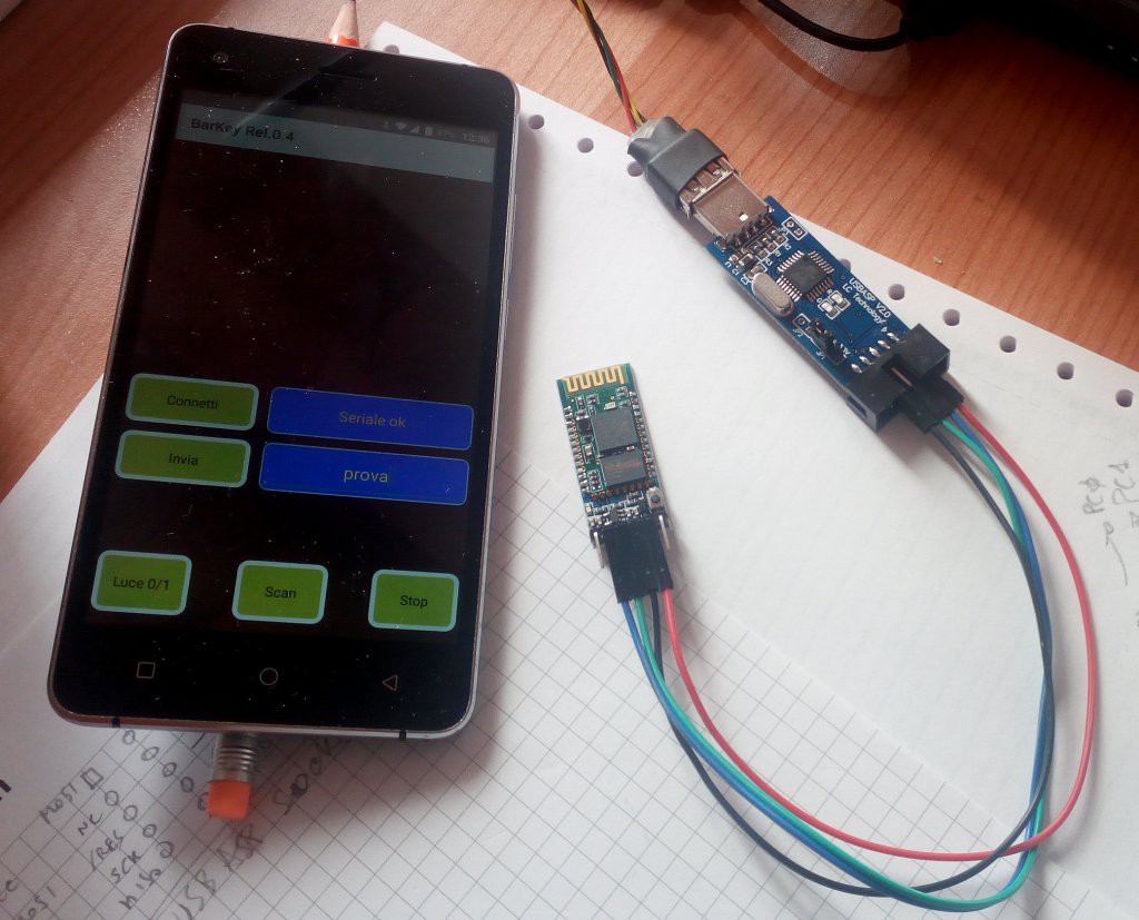
Here's what the App looks like:
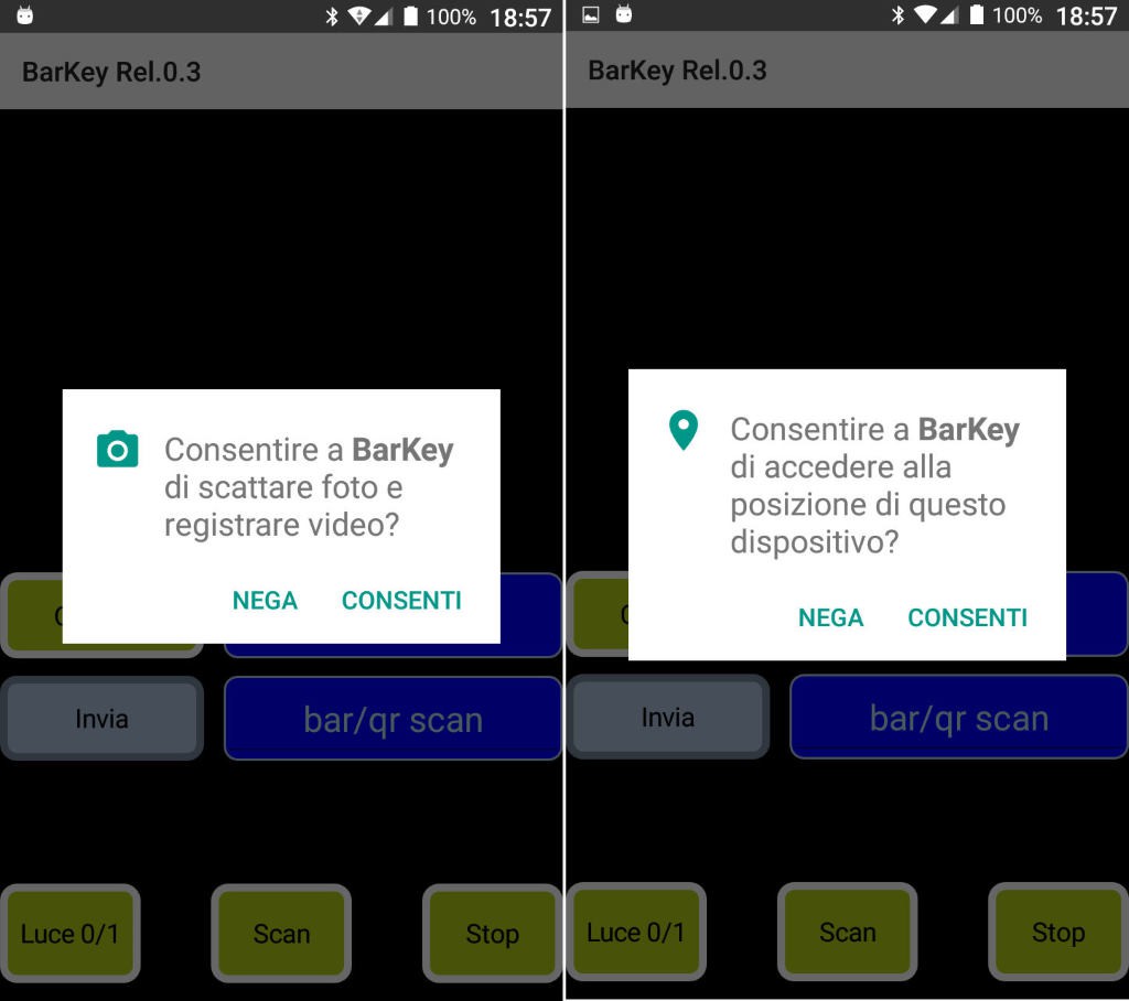
In this case, as you can see from the images, we must also give consent to the use of the CAM, because otherwise it will not be possible to retrieve the barcodes!
Once consent is given, we will have this situation:
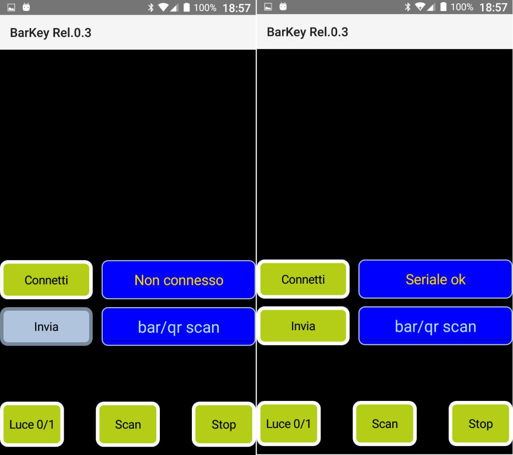
The "Connect" button is used, as in the App presented in part 2, to scan the Bluetooth devices (HC-06 Passthrough Serial) and to make the connection. The outcome of the operation, if successful, is what we see in the right part of the figure. At the bottom we find the buttons for scanning. We start a barcode scan by pressing "Scan" and we find ourselves in this condition:
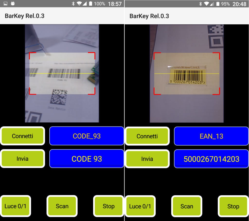
On the left, we see the result of the scan of a CODE 93 type barcode. At the top, we see the type of barcode identified, while at the bottom, in an editing window, we see the decoded text. On the right we see an example of EAN_13 barcode whose decoded text is visible in the edit window. Note that it is possible to add or remove characters in the edit window (trivial, it's an edit window!) And so, if we want, we can also insert our own text, without scanning a barcode or a QR. However, there is a limitation: when we go to transmit the code via Bluetooth (by pressing the Send button), ONLY alphabetic characters from [a] to [z] and from [A] to [Z] will be transmitted, then the numbers from [ 0] to [9] and any characters other than these will be transmitted as a space, even the space! For the moment, the transmission is carried out at the speed of 5 characters per second, but if desired this time could be reduced. If I make any changes to the App, I will replace the zip file with the new version and possibly publish a note on the differences from the previous version. The “Light 0/1” button allows you to turn on the “flash” LED in the event of poor lighting, when the barcode scan is active. The “Stop” button stops scanning when barcode scanning is active.
Barcode (QR) reader – the easy part
As I said in part 1, don't be frightened by the construction of the circuit. In fact, as I promised, I also made it using some modules that are on the market! So, nothing more to build 🙂 Only four wires to connect! Here is the circuit:
The modules used are two: the first with the ATmega8 CPU is a… programmer for micro AVRs, and exactly the “very cheap” and easily available USBASP module of which you can find all information on its inventor's website . The second is a classic HC-06 standard Bluetooth module. You can also use an HC-05 if you reprogram it to have the name HC-06, slave function and baud rate 9600.
The USBASP programmer, when you buy it, has the firmware on board to act as a programmer, so it will have to be reprogrammed (using a second device) with the new firmware that you can download from the "files" section. I have been using another type of programmer for many years, compatible with the STK500, but you can also safely use a second USBASP, the important thing is to close the JP2 jumper on the circuit you are going to program. I used the tweezers for the SMD, so as not to solder the jumper! Note that I also put the power supply selection jumper on the 3.3Volts position.
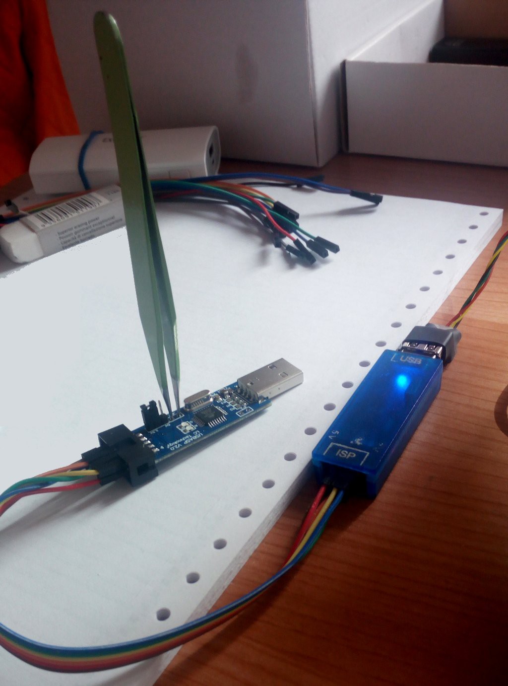
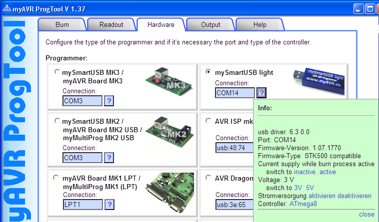
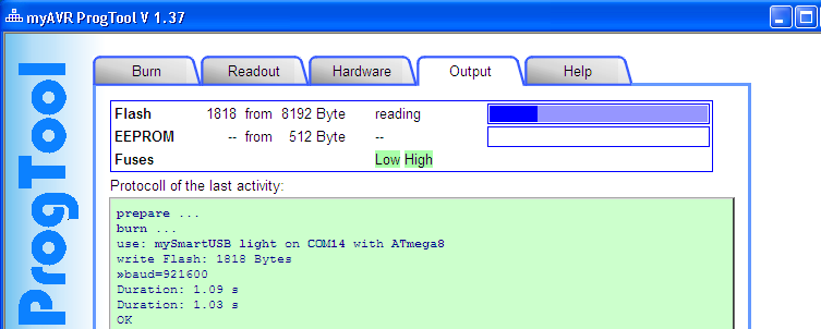
As you can see, the programmer on the right has the 6-pin connector, while the USBASP circuit has the 10-pin connector (similar to the Atmel standard, but with two GND connections replaced by TX and RX), so I used normal female-female connection wires to join the two circuits, following the name of the signals VCC, GND, MISO, MOSI, SCLK, /RES. My programmer (right) can also supply the voltage needed to program and therefore nothing else is needed. In the photo below is the programmer settings page. Once the wires are connected and the test is requested, a light green message comes out saying that everything is ok (if it isn't, a pale pink comes out).
Here is the settings page for the programmer, with the file to use to program the flash and the fuse configuration:
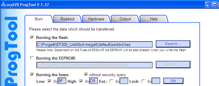
Finally, here is the result of the programming:
At this point, if you take the circuit, disconnect it from the programmer (remove the tweezers!) And connect it to a USB port on your computer, you will hear the classic sound of a connected HID and you will find an extra keyboard. To connect the HC-06 module we need 4 wires, which are: VCC, GND, TX and RX. Note that in some USBASP programmers, other than the one indicated, there is a 6-pin connector; this is not suitable for our use, as it does not provide the two basic signals TX and RX! So, use only what I have indicated or a 100% copy of it… Of course, remember to cross the serial wires, ie the USB ASP TX goes to the HC-06 RX and vice versa. By connecting everything to the USB socket, you will see the red LED of the HC-06 flashing. Pairing with the phone by providing the password (typically 1234) and if you have installed my App you can send a command, directly writing the text, or a barcode framing it with the camera.
Easier than that...
I remind you that you can download App and Firmware (hex) from the “files” section.
Notes:
210102: App BTserSend updated to Rel.0.3. If the BT HC-06 module has not already been paired with the smartphone (if the password has not been provided) a warning is shown.
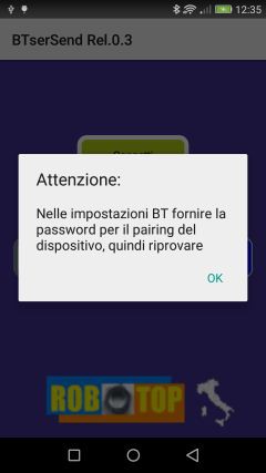
At that point, you need to go to the settings of the phone, Bluetooth devices, and make the pairing. After that, the App will be able to connect in serial without problems.
210102: BarKey App updated to Rel.0.4. It contains the same changes made to the BTserSend and adds an initialization character of the serial, since in some cases the initial character was missing from the first barcode sent.